
Related Manuals for THORLABS PM320E


Summary of Contents for THORLABS PM320E
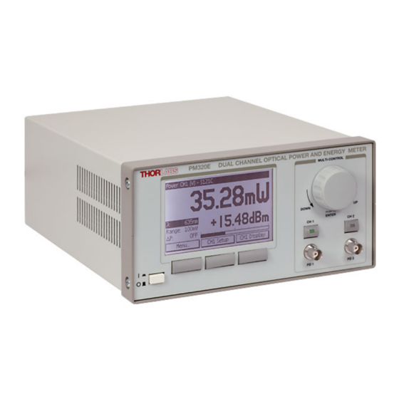
- Page 1 Thorlabs Instrumentation Optical Power and Energy Meter PM320E Operation Manual 2016...
- Page 2 Version: Date: 10-Mar-2016 Item No.: M0009-510-618 Copyright © 2016 Thorlabs GmbH...
-
Page 3: Table Of Contents
Contents Foreword 1 General Information 1.1 Safety 1.2 Ordering Codes and Accessories 2 Getting Started 2.1 Parts List 2.2 Preparation 2.3 Operating Elements 2.3.1 Front Panel 2.3.2 Rear Panel 2.3.3 Main Displays 3 Operating Instruction 3.1 Sensor Independent Settings and Operation 3.1.1 Navigating the Menus 3.1.2... - Page 4 3.8 Histogram Mode (Energy Sensors) 3.9 System Configuration 3.10 Analog Output 3.11 Miscellaneous Analog Output 4 Remote Operation 4.1 Connecting a Computer 4.2 PM320E Utility Software 5 Command Reference 5.1 Common IEEE488.2 Commands 5.2 Measurement Commands 5.3 Device Setup Commands 5.4 Sensor Commands 5.5 MISC-Output Commands...
- Page 5 8.6 Thorlabs 'End of Life' Policy 8.7 Thorlabs Worldwide Contacts...
-
Page 6: Foreword
Paragraphs preceeded by this symbol explain hazards that could damage the instrument and the connected equipment or may cause loss of data. Note This manual also contains "NOTES" and "HINTS" written in this form. Please read these advices carefully! © 2016 Thorlabs GmbH... -
Page 7: General Information
Prior to applying power to the PM320E, make sure that the protective conductor of the 3 conductor mains power cord is correctly connected to the protective earth ground... -
Page 8: Ordering Codes And Accessories
Thorlabs is not responsible for any radio television interference caused by modifications of this equipment or the substitution or attachment of connecting cables and equipment other than those specified by Thorlabs. The correction of interference caused by such unauthorized modification, substitution or attachment will be the responsibility of the user. -
Page 9: Getting Started
After switching on the unit, the graphics display will show the device status and then jump to the dual channel screen. The PM320E is immediately ready to use after turning on. The rated accuracy is reached, however, after a warming-up time of approx. 10 minutes. -
Page 10: Operating Elements
PM320E 2.3 Operating Elements 2.3.1 Front Panel Display Control Knob Power Switch Soft Keys Display Selector CH1 Photo Diode Input CH1 Photo Diode Input CH2 Display Selector CH2 © 2016 Thorlabs GmbH... -
Page 11: Rear Panel
USB Interface Connector (Type B) MISC Output Connector (BNC) CH1 Sensor Connector (DSUB 9 Pin female) Analog Output CH1 (BNC) CH2 Sensor Connector (DSUB 9 Pin female) Analog Output CH2 (BNC) Mains Connector including Line Voltage Switch and Line Fuses © 2016 Thorlabs GmbH... -
Page 12: Main Displays
PM320E 2.3.3 Main Displays Main Display - Single Channel (CH1) Main Display - Dual Channel Display Power Trend Graph CH2 Display Power Statistics CH2 © 2016 Thorlabs GmbH... - Page 13 2 Getting Started Display Energy Statistics CH2 Display Energy Histogram CH1 © 2016 Thorlabs GmbH...
-
Page 14: Operating Instruction
3.1 Sensor Independent Settings and Operation 3.1.1 Navigating the Menus The PM320E is controlled by three display/menu dependent soft buttons below the graphics display and/or the multi-control knob (rotary knob with push button) that combines Selecting with an Edit / Enter functionality. All displays have directly accessible settings by navigating and clicking with the multi-control knob. -
Page 15: Readout Configuration
Ratio CH1/CH2, CH2/CH1 [dB] Power Difference: CH1-CH2, CH2-CH1 [W] TH Adapter Voltage [V] Voltage [V] Power [W] Power [W] Power [dBm] Power [dBm] Delta Power [W] Delta Power [dB] Ratio CH1/CH2, CH2/CH1 [dB] Power Difference: CH1-CH2, CH2-CH1 [W] © 2016 Thorlabs GmbH... -
Page 16: Range Setting
PM320E 3.1.4 Range Setting Depending on the used sensor, the PM320E provides: · up to 6 current related power measurement ranges, selectable manually or in auto ranging mode · up to 3 voltage related power measurement ranges, selectable manually or in auto ranging mode ·... -
Page 17: Setting An Attenuation Factor
Exit the setup menu. 3.1.7 Trigger Input For power and energy measurements the PM320E has two trigger modes that can be selected for each channel in the CHx Setup under <Trigger Source>: Depending on the connected sensor the selected trigger source has the function shown in the table below. -
Page 18: Photodiode Power Sensor Operation
PM320E 3.2 Photodiode Power Sensor Operation Photodiode sensors of the Thorlabs S1xxC series can be connected to each of the Sub-D jacks in the rear panel. The sensor will be recognized immediately after plugging. With a power meter sensor plugged-in at the rear panel, the related photo-diode input in the front panel is disabled. -
Page 19: Dark Current Adjustment
(laser switched off) and press the Control knob or press the <Enter> soft button. The PM320E will automatically switch down to the smallest possible measurement range, measure the photo current and take in account this value when calculating the power reading. -
Page 20: Thermal Power Sensor Operation
PM320E 3.3 Thermal Power Sensor Operation Thermal sensors of the Thorlabs S3xxC series can be connected to both CH1 and CH2 Sub-D jacks in the rear panel. The sensor will be recognized immediately after plugging in. With a power meter sensor plugged-in at the rear panel, the related photo-diode input in the front panel is disabled. -
Page 21: Custom Thermal Elements
· Connect a resistor (1 kW to 10 kW) between pin 7 (PRESENT) and 3 (GND). The PM320E will recognize a ‘Thermal Head Adapter’. The read-out will be in Volts or - if a responsivity factor in V/W has been entered - also as power value in Watts or dBm. -
Page 22: Pyroelectric Energy Sensor Operation
The trigger level can be adjusted between 1% and 70% of each energy range. Only pulses that are higher than the adjusted trigger level are recognized by the PM320E. The trigger level should be set between the noise level and the expected pulse height. -
Page 23: Custom Pyroelectric Sensors
· Connect a resistor (1 kW to 10 kW) between pin 7 (PRESENT) and 3 (GND). The PM320E will recognize a ‘Pyro Head Adapter’. The read-out will be in Volts or - if the responsivity factor in V/J has been entered - also as energy value in Joules or average power value in Watts. -
Page 24: Power Measurement Using Photo Diodes
PM320E 3.5 Power Measurement Using Photo Diodes Common photodiodes or Thorlabs packaged photodiodes of the SM05PD and SM1PD Series can be connected to both BNC jacks in the front panel. The BNC input is automatically enabled when no power meter sensor or adapter is connected to the related 9 pin DSUB connector in the rear. -
Page 25: Statistics Mode
Clicking the control button resets the graph. The time base can be set from 100ms/div up to 1h/div so that up to 16 hours can be monitored on one screen. This screen can be accessed only with power sensors or photodiodes. © 2016 Thorlabs GmbH... -
Page 26: Histogram Mode (Energy Sensors)
The signals from the analog outputs are not wavelength corrected. The voltage is range dependent within the interval from -10V to +10V. © 2016 Thorlabs GmbH... -
Page 27: Miscellaneous Analog Output
The voltage from this output can be configured in the ‘Misc Output Configuration’ in the main ‘Menu’ in terms of each possible power or energy read out (Measurement Value), gain (Output Sensitivity) and offset (Offset Voltage). Display MISC OUT Configuration © 2016 Thorlabs GmbH... -
Page 28: Remote Operation
PC which you are performing the installation. Prior to connecting the PM320E to the PC, please insert the CD that is shipped with the instrument and install the PM320E drivers. When the following message appears after the... - Page 29 4 Remote Operation The identification string contains the following items: Thorlabs Vendor ID = 0x1313 Product ID: 0x8022 = PM320E Serial number The utility software will recognize and update connected sensors while the program is running. The display data can be logged to a file after pressing the <START> and <Log To File>...
-
Page 30: Command Reference
Sets the ‘OPC’ bit in the ‘Standard Event Status Register’ (see also IEEE488.2- 1992-§10.18). Operation Complete Query Command format: *OPC? Response format: <NR1 NUMERIC RESPONSE DATA> Description: The Operation Complete Query places a ‘1’ into the device’s output queue (see also IEEE488.2-1992-§10.19). © 2016 Thorlabs GmbH... - Page 31 Clear Status Command Command format: *CLS Prerequisite: None Description: Clears the following device’s status registers (see also IEEE488.2-1992-§10.3): · Standard Event Status Register · Device Error Event Register · Device Operation Event Register · Device Error Queue © 2016 Thorlabs GmbH...
-
Page 32: Measurement Commands
Note: The averaging rate does not influence the front panel display. The instrument measures at 500Hz rate. Use this value to achieve an appropriate line filtering. To achieve a good 60Hz filtering use a multiple of 25. To achieve a good 50Hz filtering use a multiple of 10. © 2016 Thorlabs GmbH... - Page 33 Photodiode current <NR3 NUMERIC RESPONSE DATA> Description: Queries the channel 1/2 measured photodiode current in Ampere [A]. Note: If an overflow occurs the value ‘+Inf’ or ‘-Inf’ is returned. Voltage Query (channel 2 PM320E only) Command format: :VOLT[1,2]:VAL? Response format: Thermopile voltage <NR3 NUMERIC RESPONSE DATA>...
- Page 34 Thermopile voltage <NR3 NUMERIC RESPONSE DATA> Description: Queries the channel 1/2 measured thermopile voltage value in Volt [V] of the measurement started by :MEAS:INIT[1,2]. Note: If an overflow occurs the value ‘+Inf’ or ‘-Inf’ is returned. © 2016 Thorlabs GmbH...
- Page 35 Queries the channel 1/2 measured average pulse power density value in Watts per square cm [W/cm²] of the measurement started by :MEAS:INIT[1,2]. (i.e. D × repition frequency) ENERGY Note: If an overflow occurs the value ‘+Inf’ or ‘-Inf’ is returned. © 2016 Thorlabs GmbH...
-
Page 36: Device Setup Commands
Set the channel 1/2 photodiode input BIAS voltage Query the channel 1/2 photodiode input BIAS voltage :PDBIAS[1,2]:VAL? :PDBIAS[1,2]:RNG? Query the channel 1/2 photodiode input BIAS voltage range :THACCEL[1,2] Set the channel 1/2 thermopile accelerator state. :THACCEL[1,2]? Query the channel 1/2 thermopile accelerator state. © 2016 Thorlabs GmbH... - Page 37 <CHARACTER RESPONSE DATA> [AUTO,R1NW,R10NW,R100NW,R1UW,R10UW,R100UW,R1MW,R10MW, R100MW,R1W,R10W,R100W,R1KW] Description: Queries the channel 1/2 power range. Query Channel 1/2 Minimum Power Range Command format: :PRANGE[1,2]:MIN? Response format: <CHARACTER RESPONSE DATA> [AUTO,R1NW,R10NW,R100NW,R1UW,R10UW,R100UW,R1MW,R10MW, R100MW,R1W,R10W,R100W,R1KW] Description: Queries the channel 1/2 minimum settable power range. © 2016 Thorlabs GmbH...
- Page 38 Description: Queries the channel 1/2 minimum settable thermopile voltage range. Query Channel 1/2 Maximum Thermopile Voltage Range Command format: :URANGE[1,2]:MAX? Response format: <CHARACTER RESPONSE DATA> [AUTO,R1MV,R10MV,R100MV,R1V] Description: Queries the channel 1/2 maximum settable thermopile voltage range. © 2016 Thorlabs GmbH...
- Page 39 Sets the channel 1/2 wavelength [nm] to use for calculating the sensor sensitivity. Query Channel 1/2 Wavelength Command format: :WAVEL[1,2]:VAL? Response format: currently used wavelength <NR3 NUMERIC RESPONSE DATA> Description: Queries the channel 1/2 currently used wavelength [nm]. © 2016 Thorlabs GmbH...
- Page 40 Description: Sets the channel 1/2 photodiode responsivity [A/W]. Query Channel 1/2 Photodiode Responsivity Command format: :PDRESP[1,2]:VAL? Response format: currently used photodiode responsivity <NR3 NUMERIC RESPONSE DATA> Description: Queries the channel 1/2 currently used photodiode responsivity [A/W]. © 2016 Thorlabs GmbH...
- Page 41 Sets the channel 1/2 thermal time constant [s]. (used only with thermopile adaptors) Query Channel 1/2 Thermal Time Constant Command format: :THTIMECONST[1,2]:VAL? Response format: currently used thermal time constant <NR3 NUMERIC RESPONSE DATA> Description: Queries the channel 1/2 currently used thermal time constant [s]. © 2016 Thorlabs GmbH...
- Page 42 [AUTOPOWER, EXTERNPOWER, AUTOENERGY, EXTERNENERGY] Description: Sets the trigger mode for channel 1/2. Query Channel 1/2 Trigger Mode Command format: :TRIGMODE[1,2]? Response format: <CHARACTER PROGRAM DATA> [AUTOPOWER, EXTERNPOWER, AUTOENERGY, EXTERNENERGY] Description: Queries the channel 1/2 trigger mode © 2016 Thorlabs GmbH...
- Page 43 Sets the sensor type to use if an adaptor is connected on channel 1/2. Query Channel 1/2 Sensor Adaptor Type Command format: :ADAPTYPE[1,2]? Response format: <CHARACTER PROGRAM DATA> [PD,TH,PY] Description: Queries the sensor type to use if an adaptor is connected on channel 1/2. © 2016 Thorlabs GmbH...
-
Page 44: Sensor Commands
Minimum wavelength [m] <NR3 NUMERIC RESPONSE DATA> , Maximum wavelength [m] <NR3 NUMERIC RESPONSE DATA> , Minimum power [W] <NR3 NUMERIC RESPONSE DATA> , Maximum power [W] <NR3 NUMERIC RESPONSE DATA> Description: Queries the optical sensor head wavelength and power ranges. © 2016 Thorlabs GmbH... -
Page 45: Misc-Output Commands
Power ratio channel 2 / channel 1 [dB] ENERGY1J Energy channel 1 [J] ENERGY2J Energy channel 2 [J] OFFSET Offset voltage [V] Query MISC-Output Operating Mode Command format: :MISCOUT:MODE? Response format: <CHARACTER RESPONSE DATA> [POW1W,POW1DBM,SUB12,RATIO12,POW2W,POW2DBM,SUB21,RATIO21, ENERGY1J,ENERGY2J,OFFSET] Description: Queries the MISC-Output operating mode. © 2016 Thorlabs GmbH... - Page 46 :MISCOUT:SENS:DBM <CHARACTER PROGRAM DATA> [R0_1DBM,R0_3DBM,R1DBM,R3DBM,R10DBM] Description: Sets the MISC-Output sensitivity for dBm modes according to the following table: R0_1DBM 1V / 0.1dBm R0_3DBM 1V / 0.3dBm R1DBM 1V / 1dBm 1V / 3dBm R3DBM R10DBM 1V / 10dBm © 2016 Thorlabs GmbH...
- Page 47 1V / 30mJ R30MJ R100MJ 1V / 100mJ R300MJ 1V / 300mJ 1V / 1J 1V / 3J R10J 1V / 10J R30J 1V / 30J R100J 1V / 100J R300J 1V / 300J R1KJ 1V / 1kJ © 2016 Thorlabs GmbH...
- Page 48 Command format: :MISCOUT:OFFS:RNG? Response format: minimum offset voltage [V] <NR3 NUMERIC RESPONSE DATA>, maximum offset voltage [V] <NR3 NUMERIC RESPONSE DATA>, default offset voltage [V] <NR3 NUMERIC RESPONSE DATA> Description: Queries the MISC-Output offset voltage range. © 2016 Thorlabs GmbH...
-
Page 49: Device Status Commands
Queries the device’s Operation Condition Register (see also chapter ‘Status Reporting’ in this document). Query Device Operation Event Register Command format: :STAT:OPER:EVT? Response format: <NR1 NUMERIC RESPONSE DATA> Description: Queries the device’s Operation Event Register (see also chapter ‘Status Reporting’ in this document). © 2016 Thorlabs GmbH... - Page 50 Sets the device’s Operation Event Enable Register (see also chapter chapter ‘Status Reporting’ in this document). Query Device Operation Event Enable Register Command format: :STAT:OPER:ENA? Response format: <NR1 NUMERIC RESPONSE DATA> Description: Queries the device’s Operation Event Enable Register (see also chapter ‘Status Reporting’ in this document). © 2016 Thorlabs GmbH...
-
Page 51: General System Commands
MM is the month, DD is the day of the month, YYYY is the year, hh is the hour, mm is the minute, ss is the second. Set Display Brightness Command format: :SYST:BRIGHT <DECIMAL NUMERIC PROGRAM DATA> Description: Sets the display brightness in the range of 0 (backlight off) and 100. © 2016 Thorlabs GmbH... - Page 52 Sets the device line filter setting. Note: For optimum device operation set the line filter to your local mains frequency. Query Linefilter Command format: : SYST:LINEFILTER? Response format: <CHARACTER RESPONSE DATA>[50HZ,60HZ] Description: Queries the device line filter setting © 2016 Thorlabs GmbH...
-
Page 53: Status Reporting
The Device Operation Status Structure reflects device states. Bits in the according event register are rising edge and falling edge triggered. Bit # Mnemonic Description reserved 15..9 Zero procedure running channel 2 reserved 7..1 Zero procedure running channel 1 © 2016 Thorlabs GmbH... -
Page 54: Error Reporting
Unknown command Invalid number of command parameters Erroneous decimal command parameter Erroneous nondecimal command parameter Erroneous char/string command parameter Invalid character program data value Adjustment data invalid Adjustment data set invalid by user Device setup data corrupt © 2016 Thorlabs GmbH... - Page 55 No PD polarity switching during BIAS on Authentication required for operation Authentication failed Operation is not allowed in SERVICE-MODE Operation is allowed in SERVICE-MODE only No or not supported sensor Operation not allowed for this sensor © 2016 Thorlabs GmbH...
-
Page 56: Measurement Considerations
· The temperature should be stable over the time of the measurement. 6.3 Power Measurement of Pulsed Signals The PM320E will read the average value of a pulsed signal when the following conditions apply: · Thermal sensor: The pulse length, repetition rate and peak power are not critical as long as the peak power is lower than the damage threshold of the sensor. -
Page 57: Line Width Of Light Sources
When entering the center wavelength of the light source as operation wavelength the PM320E will nearly show the right optical power for a symmetrical spectral response shape. -
Page 58: Beam Diameter Vs. Active Sensor Area
A second topic to consider are the maximum allowed power and energy densities of the sensor. The maximum ratings are given in the sensor spec sheet. The PM320E can display the actual power or energy density for a known beam diameter. For high power or high energy beams a good efficiency can be reached to chose a detector with an active area that is about 20% - 30% larger than the beam diameter. -
Page 59: Maintenance And Service
7 Maintenance and Service 7 Maintenance and Service Protect the PM320E from adverse weather conditions. The PM320E is not water resistant. Attention To avoid damage to the instrument, do not expose it to spray, liquids or solvents! If necessary the unit and the display can be cleaned with a cloth dampened with water. -
Page 60: Exchange Mains Fuses
Attention To avoid risk of fire the appropriate fuses for the corresponding line voltage must be used. 1. Turn off the PM320E and disconnect the mains cable. 2. The fuse holder (see figure in section Line Voltage Setting) is located below the 3-pole power connector of the mains jack. -
Page 61: Firmware Update
Firmware upgrades can be done by the user via the USB interface. Therefore install the DFU (device firmware upgrade) wizard from the distribution CD. Connect the PM320E to an USB port of your PC and launch the DFU wizard from the start bar. Follow the wizard instructions. -
Page 62: Troubleshooting
PM320E 7.4 Troubleshooting Ø Unit does not work at all (no display at the front) § Is the PM320E connected properly to the mains? - Check the mains cable and the line voltage setting. § Is the PM320E turned on? - Turn on the mains switch of your PM320E. -
Page 63: Appendix
1 x 10 10 V 1 mV +/- 0.5% f.s. 1.5 kHz 1 x 10 100 µV +/- 0.5% f.s. 1.5 kHz 1 x 10 100 mV 10 µV +/- 0.5% f.s. 1.5 kHz 1 x 10 © 2016 Thorlabs GmbH... -
Page 64: Analog Outputs
Dimensions (W x H x D) 220 x 122 x 325 mm (with operating elements) Weight < 4 kg ) non-condensing All technical data are valid at 23 ± 5°C and 45 ± 15% rel. humidity (non condensing) © 2016 Thorlabs GmbH... -
Page 65: Pin Assignment Of The Sensor Connector
EEPROM Digital I/O Attention This pin is uniquely used for the memory in the sensor head and must not be used. Connecting this pin may cause malfunction of the PM320E photodiode ground (anode), thermal and pyro sensor ground, analog ground photodiode cathode... -
Page 66: Certifications And Compliances
Emissions, which exceed the levels required by these standards, may occur when this equipment is connected to a test object. Modulation input port capped at IEC 61000-4-3 test. Replaces 73/23/EEC, amended by 93/68/EEC Performance Criterion C was reached at additional test levels according to EN 61326-1:2006 table 2 © 2016 Thorlabs GmbH... -
Page 67: Warranty
For warranty repairs or service the unit must be sent back to Thorlabs GmbH. The customer will carry the shipping costs to Thorlabs GmbH, in case of warranty repairs Thorlabs GmbH will carry the shipping costs back to the customer. -
Page 68: Copyright And Exclusion Of Reliability
User Manual. Should you require further information on this product, or encounter specific problems that are not discussed in sufficient detail in the User Manual, please contact your local Thorlabs GmbH dealer or system installer. - Page 69 Waste treatment on your own responsibility If you do not return an “end of life” unit to Thorlabs GmbH, you must hand it to a company specialized in waste recovery. Do not dispose of the unit in a litter bin or at a public waste disposal site.
- Page 70 Email: europe@thorlabs.com Email: scandinavia@thorlabs.com France Brazil Thorlabs SAS Thorlabs Vendas de Fotônicos Ltda. 109, rue des Côtes Rua Riachuelo, 171 78600 Maisons-Laffitte São Carlos, SP 13560-110 France Brazil Tel: +33-970 444 844 Tel: +55-16-3413 7062 Fax: +33-811 38 17 48 Fax: +55-16-3413 7064 www.thorlabs.com...
Need help?
Do you have a question about the PM320E and is the answer not in the manual?
Questions and answers