Table of Contents
Advertisement
Quick Links
Advertisement
Table of Contents

Related Manuals for THORLABS TPZ001


Summary of Contents for THORLABS TPZ001
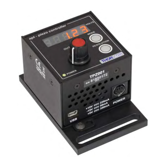
- Page 1 TPZ001 Piezo Driver User Guide Original Instructions...
-
Page 2: Table Of Contents
Contents Chapter 1 Safety ..................... 4 1.1 Safety Information .................. 4 1.2 General Warnings .................. 4 Chapter 2 Overview and Setup ..............5 2.1 Introduction ..................... 5 2.2 T-Cube Controller Hub ................6 2.3 Kinesis PC Software Overview ............... 7 2.3.1 Introduction ...................... - Page 3 Appendix A Connector Pinout Details ............48 Appendix B Preventive Maintenance ............49 Appendix C Specifications and Associated Products ......50 Appendix D Piezo Operation - Background ..........52 Appendix E Regulatory ................55 Appendix F Thorlabs Worldwide Contacts ..........59...
-
Page 4: Chapter 1 Safety
This product generates, uses and outputs high voltages from the SMC connector (HV Output) that are hazardous and can cause serious injury. In any installation that uses the TPZ001 it is the user’s responsibility to ensure adequate insulation and precuations are taken to avoid shock risk. Cables for HV Out must be rated for 250 V RMS. -
Page 5: Chapter 2 Overview And Setup
This driver is capable of delivering up to 150V of drive voltage at 7.5mA - allowing operating bandwidths up to 1kHz (see specs). The TPZ001 provides immediate 'out of the box' operation with the Thorlabs complete range of bare piezo stacks, piezo equipped actuators and piezo driven mirror mounts. -
Page 6: T-Cube Controller Hub
2.2 T-Cube Controller Hub As a further level of convenience when using the new T-Cube Controllers Thorlabs also offers the new T-Cube Controller Hub (TCH002). This product has been designed specifically with multiple T-Cube operation in mind in order to simplify issues such as cable management, power supply routing, multiple USB device communications and different optical table mounting scenarios. -
Page 7: Introduction
HPVEE, Matlab, VB.NET, C#.NET and, via VBA, Microsoft Office applications such as Excel and Word. Consider the control supplied for the TPZ001 Piezo driver unit. This Control provides a complete user graphical instrument panel to allow the piezo unit to be manually operated, as well as a complete set of software functions to allow all parameters to be set and operations to be automated by a client application. -
Page 8: Software Upgrades
This is available either by pressing the F1 key when running the Kinesis server, or via the Start menu, Start\Programs\Thorlabs\Kinesis\Kinesis Help. 2.3.3 Software Upgrades Thorlabs operate a policy of continuous product development and may issue software upgrades as necessary. HA0143T Rev 12K Sept 2015... -
Page 9: Chapter 3 Getting Started
If you experience any problems when installing software, contact Thorlabs on +44 (0)1353 654440 and ask for Technical Support. DO NOT CONNECT THE CONTROLLER TO YOUR PC YET 1) Go to Services/Downloads at www.thorlabs.com and download the software. -
Page 10: Mechanical Installation
3.2 Mechanical Installation Warning The safety of any system incorporating this equipment is the responsibility of the person performing the installation. 3.2.1 Environmental Conditions Warning Operation outside the following environmental limits may adversely affect operator safety. Location Indoor use only Maximum altitude 2000 m Temperature range... -
Page 11: Removing The Baseplate
T-Cube Piezo Driver 3.2.3 Removing the Baseplate The baseplate must be removed before the rubber feet (supplied) can be fitted, or the unit is connected to the USB controller hub.. Detail A Detail B Baseplate attachment screws Baseplate removed and rubber feet fitted Fig. -
Page 12: Electrical Installation
Note The TPZ001 has two main, selectable output voltage ranges of 0 to 75V or 0 to 150V, to allow driving piezo actuators with different drive requirements. (In addition, there is a 100V limit for operation under software control). -
Page 13: Using The Tch002 Controller Hub
T-Cube Piezo Driver Note Thorlabs supply a variety of SMA to BNC and SMC to BNC adaptor and extension cables. Please see our catalog, or visit www.Thorlabs.com for further details. 3.3.2 Using The TCH002 Controller Hub The TCH002 USB Controller Hub provides power distribution for up to six T-Cubes, and requires only a single power connection. -
Page 14: Connecting To A Standalone Power Supply
3) The Version number of the embedded software is displayed for a few seconds. Thorlabs offers a compact, two-way power supply unit (TPS002), allowing up to two piezo driver T-Cubes to be powered from a single mains outlet. However, if an external supply is to be used, see Appendix A.1 for power supply connector pin out... -
Page 15: Connect The Hardware
Wait while Windows installs the drivers for the new hardware. 7) For maximum accuracy, wait approximately 30 mins for the unit to thermally stabalize to the environment. 8) Run the Kinesis software - Start/All Programs/Thorlabs/Kinesis/Kinesis. -
Page 16: Chapter 4 Standalone Operation
Persons using the TPZ001 controller must understand the hazards associated with using high voltages and the steps necessary to avoid risk of electrical shock. If the TPZ001 is used in a manner not specified by Thorlabs, the protective features provided by the product may be impaired. -
Page 17: Control Panel Buttons And Indicators
4.2 Control Panel Buttons and Indicators apt - piezo controller VOLTS MODE OUTPUT RESOLUTION POWER Fig. 4.1 Panel Controls and Indicators VOLTS Display - Shows the voltage applied to the piezo actuator/stack. OUTPUT Potentiometer - Used to set the voltage applied to the piezo actuator/ stack. -
Page 18: Button Operation
Chapter 4 4.4 Button Operation 4.4.1 Resolution Button The resolution button toggles the behaviour of the OUTPUT control, between ‘Coarse’ and ‘Fine’ adjustment. In ‘Coarse’ mode, one revolution of the pot varies the output by a factor of 10 greater than in ‘Fine’... - Page 19 T-Cube Piezo Driver Press the MODE button to enter the Settings menu. Output Voltage Limits The piezo actuator connected to the cube has a specific maximum operating voltage range. Press the MODE button to select the maximum output voltage associated with your piezo actuator, 75V, 100V or 150V. Press and hold the MODE button to save the setting.
- Page 20 Cube Strain Gauge Reader unit (TSG001), high precision closed loop operation is possible using the complete range of feedback equipped piezo actuators available from Thorlabs - see Section 5.3.1. for schematic diagrams of open and closed loop operation. Press the MODE button to select Open or Closed loop control.
-
Page 21: External Inputs
Of these 3 external inputs, Ch 1 and Ch 2 are routed via the TCH002 T-cube controller hub, allowing the TPZ001 to be controlled by other cubes on the hub. For example, a combination of a TPZ001 unit with a TSG001 Strain Gauge Reader allows closed loop operation, or two TPZ001 units with a TNA001 NanoTrak cube allows optical beam alignment. - Page 22 Note. This setting applies only to open loop mode, where using an external signal to control the TPZ001 is optional. Closed loop operation is only possible if there is an external feedback signal connected to the unit, so the selected external input is always assumed to have a signal source driving it.
-
Page 23: Chapter 5 Pc Operation - Tutorial
This tutorial shows how the Kinesis application provides all of the functionality necessary to operate the hardware. 1) Power up the hardware, and wait until the TPZ001 has finished booting up, then run the Kinesis software - Start/All Programs/Thorlabs/Kinesis/Kinesis. Note For maximum accuracy, wait approximately 30 mins for the unit to thermally stabalize to the environment. -
Page 24: Introduction To Open And Closed Loop Operation
For the Thorlabs range of piezo actuators, the TSG001 strain gauge reader is a fully self contained unit that is designed to work with the TPZ001 in closed loop mode, providing the feedback signal necessary for closed loop operation. -
Page 25: Description Of Closed Loop Mode
T-Cube Piezo Driver The output voltage is controlled by the DSP, allowing the Kinesis server to set the output voltage. The output voltage can also be controlled by the top panel potentiometer. In addition, one of the 3 possible external inputs (SMA input, Hub Channel 1 or Hub Channel 2) can also be added to the signal that controls the output voltage. -
Page 26: Open Loop Operation
Chapter 5 5.4 Open Loop Operation The following procedures explain how the piezo actuator is driven. In open loop mode, the piezo can be positioned in three ways: by entering a voltage, by using the ‘Output’ potentiometer or by clicking the ‘Jog’ buttons. 5.4.1 Entering the piezo voltage 1) Click the Set Arrow to display the Target window.. -
Page 27: Using The Controller As A Piezo Amplifier
T-Cube Piezo Driver 5.4.3 Using the Controller as a Piezo Amplifier Certain applications may require the piezo to be driven by a voltage generated from an external source (e.g. a signal generator). The piezo T-Cube is designed to accept an external 0 to 10V signal and handle the amplification from 10V to 75 or 150V. As an example, the following procedure explains how to configure the unit as a piezo amplifier. -
Page 28: Operation With Other Members Of The T-Cube Family
5.5 Operation with Other Members of the T-Cube Family 5.5.1 Introduction The operation of the TPZ001 piezo controller can be extended when the unit is used in conjunction with other members of the T-Cube family. Specifically, 2 other controllers have been designed to work closely with the TPZ001 piezo unit; the TSG001 strain gauge reader and the TNA001 NanoTrak autoalignment controller. - Page 29 Wait while Windows installs the drivers for the new hardware. 9) Run the Kinesis software - Start/All Programs/Thorlabs/Kinesis/Kinesis. 10) Click the ‘Settings’ button on GUI of the Piezo Driver to display the Settings panel (shown below).
- Page 30 Chapter 5 Note To identify the piezo unit associated with the GUI panel, click the ‘Ident’ button; the Power LED and the Display of the asssociated controller flashes for a short period. Fig. 5.8 Piezo Driver Settings 11) Make the following parameter settings, as shown in Fig. 5.8 Control Tab Loop Mode - Select Closed Loop Maximum Voltage - Set the corresponding voltage for the piezo being...
- Page 31 T-Cube Piezo Driver 14) Click the ‘Settings’ button on GUI of the Strain Gauge Reader fitted in bay 2, to display the Settings panel (shown below). Note To identify the strain gauge unit associated with a GUI panel, click the ‘Ident’...
-
Page 32: Piezo Driver Hub Mounting Options
Chapter 5 5.6.2 Piezo Driver Hub Mounting Options. When the T-Cube piezo driver is used on the hub, together with the TSG001 strain gauge unit, signals can be routed via dedicated internal communication channels. These channels are selected via the piezo unit settings panel, or via the ‘MODE’ button on the top panel of the unit. - Page 33 T-Cube Piezo Driver all units set to Hub Channel 2 bay 1 bay 2 bay 3 bay 4 MODE MODE POSITION POSITION VOLTAGE VOLTAGE FORCE FORCE POWER POWER Hub Channel 1 Hub Channel 2 bay 2 bay 3 bay 5 bay 6 MODE MODE...
-
Page 34: Electrical Connections And Software Settings - Off Hub Operation
5.6.3 Electrical Connections and Software Settings - Off Hub (Hard Wired) Operation The following procedure describes a typical set up, when a TPZ001 piezo driver cube and a TSG001 Strain Gauge Reader are used to control a piezo actuated stage - see Fig. - Page 35 T-Cube Piezo Driver 10) Click the ‘Settings’ button on the GUI panel of the Piezo Driver to display the Settings panel (shown below). . Fig. 5.13 Piezo Driver Settings 11) Make the following parameter settings, as shown in Fig. 5.8 Control Tab Loop Mode - Select Closed Loop Maximum Voltage - Set the corresponding voltage for the piezo being...
-
Page 36: Entering The Piezo Percentage Position
Chapter 5 5.6.4 Entering the piezo percentage position 1) Click the Set Arrow to display the Target window.. Fig. 5.14 Target Position Popup Window 2) Enter a position as a percentage of total piezo travel. This can be entered directly into the field, or by clicking on the up/down arrows. -
Page 37: Adjusting The Piezo Position
T-Cube Piezo Driver 5.7 Adjusting the Piezo Position Note The position of the actuator is relative to the minimum position set for the arrangement using the ‘Null’ facility, see Section 5.6.5. The extension of the actuator is displayed on the Strain Gauge T-Cube as a position in microns. -
Page 38: Load Response
Chapter 5 5.8 Load Response The response of the TPZ001 to varying load and frequencies is shown below. Fig. 5.15 Response of TPZ001 to Varying Loads and Frequencies 5.9 Setting Move Sequences The Kinesis software allows move sequences to be programmed, allowing several positions to be visited without user intervention. -
Page 39: Chapter 6 Software Reference
Kinesis software. Fig. 6.1 TPZ001 Piezo Driver Software GUI Note The serial number of the TPZ001 unit associated with the GUI panel, is displayed in the top right hand corner. This information should always be provided when requesting customer support. - Page 40 Parameters Display - shows the maximum working voltage of the associated piezo actuator and the present setting for the step size Settings - Displays the 'Settings' panel, which allows the operating parameters to be entered for the motor drive - see Section 6.2. Active - lit when the unit is operating normally and no error condition exists.
-
Page 41: Settings Panel
T-Cube Piezo Driver 6.2 Settings Panel When the 'Settings' button on the GUI panel is clicked, the 'Settings' window is displayed. This panel allows data such as jog step size and input sources to be entered. Note that all of these parameters have programmable equivalents accessible through the functions on this Control (refer to the Kinesis API helpfile for further details. -
Page 42: Control Tab
When the T-Cube Piezo Driver is used in conjunction with the T-Cube Strain Gauge Reader unit (TSG001) on the T-Cube Controller Hub (TCH002), high precision closed loop operation is possible using the complete range of feedback equipped piezo actuators available from Thorlabs. HA0143T Rev 12K Sept 2015... - Page 43 30 micron piezo stack, a position setpoint of 50% equates to 15 micron. Further, when operating in closed loop mode, if you click the ‘Set’ button on the GUI of the TPZ001 you are prompted to enter a 'Position Setpoint [0-100%] - see Fig. 6.2 below.
-
Page 44: Advanced Tab
This must be set up to suit the maximum specified operating voltage of the piezo actuator connected to the unit. Most Thorlabs piezo actuators are specified for either 75V or 150V maximum operation. In general, the maximum voltage should not be exceeded because it can cause damage to the piezo actuator. - Page 45 TPZ001 unit with a TSG001 Strain Gauge Reader described above can still be used for closed loop control but in this case the TSG001 MONITOR output must be connected to the TPZ001 EXT IN input using an external SMA to SMA cable. Note...
- Page 46 Chapter 6 If Software + Potentiometer is selected, the unit sums the voltage set using front panel OUTPUT control with the voltage set using the SetVoltOutput method (or the GUI panel ‘Output’ control). If Pot_EXT_IN is selected, the unit sums the voltage set using front panel OUTPUT control with the voltage set using the SetVoltOutput method (or the GUI panel ‘Output’...
-
Page 47: Appendix A Connector Pinout Details
A.1 Power Connector A.1.1 Pin Identification Thorlabs recommends that the piezo cube is operated with Thorlabs power supply TPS002, as it was specifically designed for use with this product. However, to enable customers to use the cube in installations where a ±15V and 5V power is already available, the piezo cube can be operated with a different external power supply, such as a bench or lab supply. -
Page 48: Appendix B Preventive Maintenance
The equipment contains no user servicable parts. There is a risk of electrical shock if the equipment is operated with the covers removed. Only personnel authorized by Thorlabs Ltd and trained in the maintenance of this equipment should remove its covers or attempt any repairs or adjustments. Maintenance is limited to safety testing and cleaning as described in the following sections. -
Page 49: Appendix C Specifications And Associated Products
Appendix C Specifications and Associated Products C.1 Specifications Parameter Value Piezoelectric Output Piezo Drive Voltage 0 - 150V max. (SMC Connector) Piezo Drive Current 7.5mA max. continuous User Voltage Control Digital Potentiometer (Resolution Selectable) Output Noise < 2mV rms Typical Piezo Capacitance 1µF to 10µF Drive Bandwidth 1kHz (1µF Load, 1V p-p) - Page 50 C.2 Associated Products Product Name Part Number Drive Cable for Piezoelectric Actuators (3.0 m) PAA100 Drive Cable Extension for Piezo Actuators (3.0 m) PAA100A Drive Cable for Piezoelectric Actuators (1.5 m) PAA101 Drive Cable Extension for Piezo Actuators (1.5 m) PAA101A T-Cube Strain Gauge Reader TSG001...
-
Page 51: Appendix D Piezo Operation - Background
– see Fig. D.1. In this way, the distance from positive to negative electrodes is very small. A large field gradient can therefore be obtained with a modest drive voltage (75 V in the case of most Thorlabs actuators). expansion piezoelectric... - Page 52 Some Thorlabs nanopositioning actuators have position sensing, others do not. The Piezoelectric control module allows both types to be controlled.
- Page 53 T-Cube Piezo Driver moving open loop control part demand actuator moving closed loop control part demand a + b/s actuator sensor Fig. D.3 Open loop and closed loop control The result of using closed-loop control is a linear relationship between demand (voltage) and measured position –...
-
Page 54: Appendix E Regulatory
Appendix E Regulatory E.1 Declarations Of Conformity E.1.1 For Customers in Europe See Section E.3. E.1.2 For Customers In The USA This equipment has been tested and found to comply with the limits for a Class A digital device, persuant to part 15 of the FCC rules. These limits are designed to provide reasonable protection against harmful interference when the equipment is operated in a commercial environment. - Page 55 • left over parts of units disassembled by the user (PCB's, housings etc.). If you wish to return a unit for waste recovery, please contact Thorlabs or your nearest dealer for further information. E.2.2 Waste treatment on your own responsibility If you do not return an "end of life"...
- Page 56 Appendix E E.3 CE Certificate HA0143T Rev 12K Sept 2015...
- Page 57 T-Cube Piezo Driver...
-
Page 59: Appendix F Thorlabs Worldwide Contacts
UK and Ireland Thorlabs, Inc. Thorlabs Ltd. sales@thorlabs.com sales.uk@thorlabs.com techsupport@thorlabs.com techsupport.uk@thorlabs.com Europe Scandinavia Thorlabs GmbH Thorlabs Sweden AB europe@thorlabs.com scandinavia@thorlabs.com France Brazil Thorlabs SAS Thorlabs Vendas de Fotônicos Ltda. sales.fr@thorlabs.com brasil@thorlabs.com Japan China Thorlabs Japan, Inc. Thorlabs China sales@thorlabs.jp chinasales@thorlabs.com... - Page 60 www.thorlabs.com...
Need help?
Do you have a question about the TPZ001 and is the answer not in the manual?
Questions and answers