Table of Contents
Advertisement
Quick Links
Advertisement
Table of Contents

Related Manuals for THORLABS TLX1


Summary of Contents for THORLABS TLX1
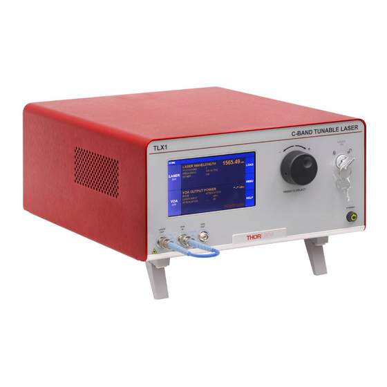
- Page 1 TLX1 / TLX2 Tunable Laser Source C-Band / L-Band User Guide...
-
Page 2: Table Of Contents
9.1. Maintenance & Repair ....................19 9.2. Replacement Parts ......................19 9.3. Replacing the Main Fuse ....................20 Chapter 10 Troubleshooting .........................21 Chapter 11 Regulatory ...........................22 Chapter 12 Declaration of Conformity ....................23 Chapter 13 Thorlabs Worldwide Contacts ..................24 Rev B, August 15, 2017... -
Page 3: Chapter 1 Warning Symbol Definitions
TLX Tunable Laser Source Chapter 1: Warning Symbol Definitions Chapter 1 Warning Symbol Definitions Below is a list of warning symbols you may encounter in this manual or on your device. Symbol Description Direct Current Alternating Current Both Direct and Alternating Current Earth Ground Terminal Protective Conductor Terminal Frame or Chassis Terminal... -
Page 4: Chapter 2 Safety
TLX Tunable Laser Source Chapter 2 Safety All statements regarding safety of operation and technical data in this instruction manual will only apply when the unit is operated correctly. If equipment is used in a manner not specified by the manufacturer, the protection provided by the equipment may be impaired. - Page 5 This product is not suitable for household room illumination. Inputs and outputs must only be connected with shielded connection cables. Only with written consent from Thorlabs may changes to single components be carried out or components not supplied by Thorlabs be used.
-
Page 6: Chapter 3 Introduction
Chapter 3 Introduction NOTE: This manual covers both the TLX1 and TLX2 models as the architectures are very similar. Only the wavelength bands are different. TLX1 covers the C-band and TLX2 covers the L-band. The differences will be clearly noted in the following sections. -
Page 7: Front And Rear Panel Overview
TLX Tunable Laser Source Chapter 3: Introduction 3.3. Front and Rear Panel Overview Label Description Detail Touchscreen display Adjustment knob Key Switch and Indicator Laser Output PM FC/PC VOA Input PM FC/PC VOA Output PM FC/PC Standby Button I/O Port HD DB-15 Option Label RS-232 Port... -
Page 8: Chapter 4 Quick Start Guide
TLX Tunable Laser Source Chapter 4 Quick Start Guide ESD CAUTION Caution – The components inside this instrument are ESD sensitive. Take all appropriate precautions to discharge personnel and equipment before making any connections to the unit. A front panel grounding jack is provided for connection to a wrist strap. -
Page 9: Controls On The Home Page
Controls on the Home Page The TLX1 can be fully controlled by using the resistive touchscreen display for all functions. You can use a finger or a plastic stylus to make selections on the screen. In addition, the knob on the front panel can be used in place of the on-screen arrow buttons for quickly changing set-point values. -
Page 10: Controls In The Settings
TLX Tunable Laser Source 4.3. Controls in the Settings Pages The Settings pages all follow the same general design and functionality as shown in the example screenshot below. The upper section with white letters displays the parameters that can be changed. Simply tap on the parameter of interest to highlight it, and the controls for that parameter will be presented. -
Page 11: Chapter 5 Operating Instructions
TLX Tunable Laser Source Chapter 5: Operating Instructions Chapter 5 Operating Instructions 5.1. Laser Settings Page To get to the Laser Settings page tap on the Laser monitors pane on the Home page. Here the user can control the laser wavelength and choose whether or not to use the dither feature to stabilize the wavelength. Turning the dither off will result in lower phase and intensity noise, but the wavelength may drift slightly over time. -
Page 12: Variable Optical Attenuator Settings Page
TLX Tunable Laser Source 5.2. Variable Optical Attenuator Settings Page To get to the Variable Optical Attenuator (VOA) Settings page tap in the VOA monitors pane on the Home page. The VOA provides the means for adjusting and stabilizing either the attenuation or the output power. Note that the power measurement units for the entire interface are set on this page. -
Page 13: Load Page
TLX Tunable Laser Source Chapter 5: Operating Instructions 5.3. Load Page To get to this page, tap the blue Load button on the Home page. The Load page allows the user to revert back to the factory default settings. Future firmware revisions will have the ability to store and load instrument states defined by the user. -
Page 14: Menu Page
LEDs that emanate from the bottom of the instrument Tap here to find help from Thorlabs Technical Support 5.4.1. Display and Sound Settings Page Path here: Home > Menu > Display & Sounds. Tap any of the fields to reach... - Page 15 TLX Tunable Laser Source Chapter 5: Operating Instructions 5.4.2. System Information Page Path here: Home > Menu > System Information. The System Information page displays the installed hardware and software versions This is useful information when in need of technical support or to verify firmware revisions 5.4.3.
- Page 16 5.4.4. Thorlabs Help Page Path here: Home > Menu > Thorlabs Help The Thorlabs Help page displays the Tech Support phone number, Thorlabs web site, and the installed hardware and software versions. This information will be useful when speaking with Tech Support.
-
Page 17: Chapter 6 Specifications
Chapter 6: Specifications Chapter 6 Specifications All Specifications are at 1550 nm and 25 °C ambient temperature, unless otherwise noted. C-band specifications apply to the model TLX1, and L-band specifications apply to the model TLX2. 6.1. Laser Specifications Parameter Value... -
Page 18: Chapter 7 Control & Pc Connections
TLX Tunable Laser Source Chapter 7 Control & PC Connections 7.1. General Purpose I/O & RS-232 Connections The back panel has two connectors for monitor and control functions. The 15-pin I/O connector provides outputs that follow the power monitors in the optical path (see block diagram). The RS-232 connector provides for basic communication with the instrument. -
Page 19: The Laser Safety Interlock
This instrument has a USB interface for connection to a computer for the purpose of loading new revisions of the firmware as they are made available via the Thorlabs website, as well as controlling the TLX series laser via SCPI type serial commands. -
Page 20: Chapter 8 Mechanical Drawings
TLX Tunable Laser Source Chapter 8 Mechanical Drawings 122.0 mm 134.8 mm (4.80") (5.31") 250.0 mm (9.84") 300.0 mm (11.81") 322.2 mm (12.69") Page 18 TTN093744-D02... -
Page 21: Chapter 9 Maintenance, Repair & Fuses
Fiber end-face cleaner for patch cords The optical connectors on the front panel may be cleaned using a 2.5 mm bulkhead cleaner such as the Thorlabs FBC1. This allows the user to clean the fiber end-face without removing it from the internal bulkhead adapter. -
Page 22: Replacing The Main Fuse
5. Investigate the fuse. This can be done with a simple continuity check. If in doubt, replace the fuse. A spare fuse is stored in the fuse holder. Additional replacement fuses can be purchased from Thorlabs. Always use fuses of the same type as the original. -
Page 23: Chapter 10 Troubleshooting
In case you experience any problems, below are a few checks to help in troubleshooting the problem. If you have any questions, please contact your local Thorlabs Technical Support office. If the unit does not appear to turn on correctly, please check the following items: ... -
Page 24: Chapter 11 Regulatory
Waste Treatment is Your Own Responsibility If you do not return an “end of life” unit to Thorlabs, you must hand it to a company specialized in waste recovery. Do not dispose of the unit in a litter bin or at a public waste disposal site. -
Page 25: Chapter 12 Declaration Of Conformity
TLX Tunable Laser Source Chapter 12: Declaration of Conformity Chapter 12 Declaration of Conformity Page 23 Rev B, August 15, 2017... -
Page 26: Chapter 13 Thorlabs Worldwide Contacts
Chapter 1 : Thorlabs Worldwide Contacts Chapter 13 Thorlabs Worldwide Contacts For technical support or sales inquiries, please visit us at www.thorlabs.com/contact for our most up-to- date contact information. USA, Canada, and South America UK and Ireland Thorlabs, Inc. Thorlabs Ltd. - Page 27 www.thorlabs.com...
Need help?
Do you have a question about the TLX1 and is the answer not in the manual?
Questions and answers