Table of Contents
Advertisement
Quick Links
Advertisement
Table of Contents

Related Manuals for THORLABS TLX3


Summary of Contents for THORLABS TLX3
- Page 1 TLX3 O-Band Tunable Laser Source User Guide...
-
Page 2: Table Of Contents
Table of Contents Introduction .......................... 2 Safety and Compliance ...................... 3 TLX3 Specifications ...................... 5 TLX3 Front and Rear Panel Functions ................ 6 TLX3 Quick Start Guide ...................... 7 TLX3 Full Operating Instructions .................. 8 6.1. Manual Mode ........................8 ... -
Page 3: Introduction
Chapter 1: Introduction Introduction The TLX3 is a turn-key, self-contained, tunable laser for the O-Band (1250 nm to 1350 nm) based on the use of a fiber-coupled, semiconductor gain module and an intracavity tunable filter. It has no moving parts, which enables fast, continuous tuning of wavelength. -
Page 4: Safety And Compliance
Only with written consent from Thorlabs may changes to single components be carried out or components not supplied by Thorlabs be used. There are no user serviceable components inside this device. - Page 5 3 meters (9.8 feet). Thorlabs is not responsible for any radio or television interference caused by modifications of this equipment or the substitution or attachment of connecting cables and equipment other than those specified by Thorlabs. The correction of interference caused by such unauthorized modification, substitution or attachment will be the responsibility of the user.
-
Page 6: Tlx3 Specifications
O-Band Tunable Laser Source Chapter 3: TLX3 Specifications TLX3 Specifications All specifications are typical at 25 °C after 1-hour warm-up time. Parameter Specification Note Wavelength Range 1250 - 1350 nm Depends on Wavelength (See Output Power 10 - 40 mW... -
Page 7: Tlx3 Front And Rear Panel Functions
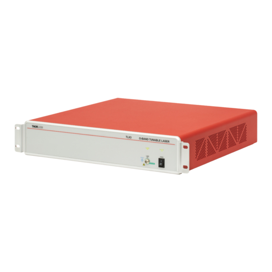
Chapter 4: TLX3 Front and Rear Panel Functions TLX3 Front and Rear Panel Functions The TLX3 comes in a 2U height rack-mount sized box with rack-mount hardware as shown here. Screw-on feet for the bottom of the box are also available for bench placement. -
Page 8: Tlx3 Quick Start Guide
Chapter 5: TLX3 Quick Start Guide TLX3 Quick Start Guide 1. Plug the TLX3 laser into the wall supply and turn on the front panel switch. 2. Install the GUI software onto a PC. The software is available here: https://www.thorlabs.com/Software The software is also supplied on a memory stick in the shipping box. -
Page 9: Tlx3 Full Operating Instructions
O-Band Tunable Laser Source Chapter 6: TLX3 Full Operating Instructions TLX3 Full Operating Instructions Follow the Quick Start Guide to get the laser connected to a PC and turned ON. The GUI should appear as shown in this image (in Manual Mode). The laser can always be turned ON and OFF using the button in the top right. The indicator light on the front panel of the actual laser should also confirm the ON/OFF state. -
Page 10: Stepped Sweep Mode
O-Band Tunable Laser Source Chapter 6: TLX3 Full Operating Instructions 6.2. Stepped Sweep Mode This mode allows you to program the laser to automatically step across a wavelength range at a user-defined step size. Click on the Stepped Sweep Mode button to enter this mode. The GUI should appear similar to the image below. -
Page 11: Continuous Sweep Mode
See the Trigger and Synchronization sections for more information about how to synchronize external equipment with the TLX3 in the Continuous Sweep Mode. Note that the Power readout will be blanked during this sweep mode because it’s changing too rapidly to be read accurately. -
Page 12: Additional Utility Functions
O-Band Tunable Laser Source Chapter 6: TLX3 Full Operating Instructions 6.4. Additional Utility Functions Additional Functions are available using the buttons across the top of the GUI as shown here: Disconnect: This button is used to disconnect any communication between the laser and the PC. Communication can be established again by pressing the “Connect”... - Page 13 The Support button provides an email address should you need technical support. Use the “Copy to Clipboard” button to capture the logfile information and then paste it into an email to techsupport@thorlabs.com. They will get back to you promptly to follow up with any problem you might have.
- Page 14 Chapter 6: TLX3 Full Operating Instructions Help: The Help button provides system information as well as several useful links to the TLX3 laser webpage, the User Manual, the Programming Guide, and any License Documentation. The TLX3 webpage provides complete specifications as well as all other documentation.
-
Page 15: Trigger And Sync Clock Outputs
O-Band Tunable Laser Source Chapter 7: Trigger and Sync Clock Outputs Trigger and Sync Clock Outputs These BNC (Female) outputs are found on the back of the unit as shown here: 7.1. Trigger Output The Trigger Out connector (BNC) provides a signal for synchronizing the sweep functions with external equipment. -
Page 16: Sync Clock Output
O-Band Tunable Laser Source Chapter 7: Trigger and Sync Clock Outputs 7.2. Sync Clock Output The Sync Clock Output provides a series of 3.3 V pulses that can be used to synchronize external instruments to the continuous sweep of the laser. The pulses are produced at a rate that depends on the sweep speed setting, and thus can also be specified in terms of picometers per pulse period. -
Page 17: Remote Control Features
GUI software package included with the TLX3. Both the RS-232 and the USB connections can be used for remotely controlling the TLX3 laser via SCPI type serial commands. Which connector to choose for remote control operation depends on the demands of the application and the user’s preference. -
Page 18: Mechanical Drawings
O-Band Tunable Laser Source Chapter 9: Mechanical Drawings Mechanical Drawings Page 17 TTN220723-D02... -
Page 19: Maintenance, Repair, & Fuses
Never use acetone. The optical connectors on the front panel may be cleaned using a 2.5 mm bulkhead cleaner such as the Thorlabs FBC250. This allows the user to clean the fiber end-face without removing it from the internal bulkhead adapter. -
Page 20: 10.1. Replacing The Main Fuses
4. Check the fuses for continuity. If in doubt, replace both fuses. Additional replacement fuses can be purchased from Thorlabs or an electronics supply house. Always use fuses of the same type as the original. 5. Reinstall the fuse holder slide into the power entry module, taking care that it fully seats until the top is flush with the rest of the power entry module. -
Page 21: Troubleshooting
In case you experience any problems, below are a few checks to help in troubleshooting the problem. If you have any additional questions, please contact your local Thorlabs Technical Support office. If the unit does not appear to turn on correctly, please check the following items: ... -
Page 22: Regulatory
Waste Treatment is Your Own Responsibility If you do not return an “end of life” unit to Thorlabs, you must hand it to a company specialized in waste recovery. Do not dispose of the unit in a litter bin or at a public waste disposal site. -
Page 23: Thorlabs Worldwide Contacts
O-Band Tunable Laser Source Chapter 13: Thorlabs Worldwide Contacts Thorlabs Worldwide Contacts For technical support or sales inquiries, please visit us at www.thorlabs.com/contact for our most up-to-date contact information. USA, Canada, and South America UK and Ireland Thorlabs, Inc. Thorlabs Ltd. - Page 24 www.thorlabs.com...
Need help?
Do you have a question about the TLX3 and is the answer not in the manual?
Questions and answers