THORLABS PM100D Operation Manuals
Optical power and energy meter
Hide thumbs
Also See for PM100D:
- Quick reference (19 pages) ,
- Operation manual (82 pages) ,
- Quick reference (12 pages)

Related Manuals for THORLABS PM100D


Summary of Contents for THORLABS PM100D
- Page 1 Operation Manual Thorlabs Instrumentation Optical Power and Energy Meter PM100D 2009...
- Page 2 Version: 17654-D02 REV E Date: 16.11.2009 © Copyright 2009, Thorlabs, Germany...
-
Page 3: Table Of Contents
3.2.3 Bottom 3.2.4 Rear Panel 3.2.5 Display Options Operating the PM100D Connecting a Power or Energy Sensor Controlling the PM100D 4.2.1 Navigating the Menus 4.2.2 System Settings ... - Page 4 IEEE488.2 Common Commands 6.4.2.1 Command summary 6.4.2.2 Command reference 6.4.2.3 PM100D specific SCPI Command Reference 6.4.3 Simple LabVIEW Example using SCPI Commands Maintenance and Repair Maintenance ...
- Page 5 Thorlabs This part of the instruction manual contains every specific information on the PM100D handheld optical power and energy meter. A general description is followed by explanations of how to operate the unit manually. You will also find information about a simple remote control of the unit.
-
Page 6: General Information
1.1 Safety 1 General Information The PM100D Handheld Optical Power and Energy Meter is designed to measure the optical power of laser light or other monochromatic or near monochromatic light sources and the energy of pulsed light sources. The space-saving, battery powered design and compatibility to all Thorlabs “C-Type”... -
Page 7: Safety
All statements regarding safety of operation and technical data in this instruction manual will only apply when the unit is operated correctly. The power meter PM100D must not be operated in explosion endan- gered environments! Sensor, photodiode and control inputs and outputs must only be connected with duly shielded connection cables. - Page 8 ▪ Consult the dealer or an experienced radio/T.V. technician for help. Thorlabs GmbH is not responsible for any radio television interfer- ence caused by modifications of this equipment or the substitution or attachment of connecting cables and equipment other than those specified by Thorlabs GmbH.
-
Page 9: Ordering Codes And Accessories
1.2 Ordering Codes and Accessories 1.2 Ordering Codes and Accessories Order Code Description PM100D Handheld Power/Energy Meter Console Photodiode Power Sensors: Order Code Type Detector Aperture Wavelength Power ∅ 9.5 S120C Compact Sensor 400 - 1100 50n - 50m S120VC... - Page 10 185 - 25000 500µ - 3 ceramic coating ES245C Pyroelectric Sensor with ∅ 45 185 - 25000 1m -15 ceramic coating Please visit our homepage http://www.thorlabs.com for various accessories like fiber adapters, posts and post-holders, data sheets and further information.
-
Page 11: Getting Started
Inspect the shipping container for damage. If the shipping container seems to be damaged, keep it until you have inspected the contents and you have inspected the PM100D mechanically and electrically. Verify that you have received the following items within the hard-case: 1. -
Page 12: Physical Overview
3.2 Physical Overview 3.2 Physical Overview 3.2.1 Front Panel Navigation Keys Enter/Edit Key λ Wavelength Key Δ Relative Meas. Key Backlight Key Figure 1 Physical Overview Front Panel 3.2.2 Side Panel On/Off Switch USB Connector Sensor Connector (DB9 female) DC Input (Charger) Analog Output (SMA) Figure 2 Physical Overview Side Panel... -
Page 13: Bottom
3.2 Physical Overview 3.2.3 Bottom Mounting Thread 1/4“-20 SD Card Slot Figure 3 Physical Overview Bottom View 3.2.4 Rear Panel Removable Protective Pull here to lift the support Rubber Boot Figure 4 Rear View... -
Page 14: Display Options
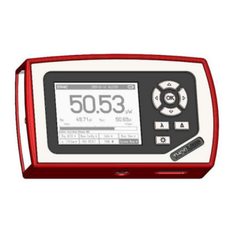
3.2 Physical Overview 3.2.5 Display Options 5 Display Options Header Line with Sensor Information, Date/Time and Battery state Status Line with Warning Annunciators Main Display Configurable Configurable Right Sub Display Left Sub Display Bar Graph Tool Tip Text Menu Soft Buttons Figure 5 Numeric Screen (Power and Energy Mode) Maximum value... - Page 15 3.2 Physical Overview Figure 7 Statistics Screen (Power Mode) Figure 8 Trend Graph (Power Mode)
- Page 16 3.2 Physical Overview Figure 9 Numeric Screen (Energy Mode) Figure 10 Statistics Screen (Energy Mode) 120mW Figure 11 Pulse Chart (Energy Mode)
-
Page 17: Operating The Pm100D
These can easily identified against older versions of Thorlabs power or energy sensors by their red connector housing. The console will not recognize sensors from the ‘A’ and ‘B’ series. Please contact Thorlabs for upgrading of old sensors with ‘C-Series’ connectors. -
Page 18: System Settings
Sets the unit to the local line frequency 50Hz/60Hz to avoid aliasing effects Default sensor Sets the PM100D in a mode to measure photo current, thermal voltage with custom detectors, or the peak voltage from a custom pyroelectric detec- tor. See chapter 7.4 about connecting custom detectors. -
Page 19: Power And Energy Measurement In The Numeric Display
Correction Reset 4.2.3.1 Range Control The PM100D provides six decades of power corresponding current and four decades of power corresponding voltage ranges. The ranges are displayed in the respectively applicable unit, depending on sensor and chosen unit. (Exception: When displaying... -
Page 20: Wavelength Correction
4.2.3.2 Wavelength Correction Most power and energy sensors show a dependent behaviour in their spectral response. For accurate measurements it is important to set the PM100D to the wavelength of the light to measure. To quickly change an operating wavelength the PM100D offers eight user adaptable soft buttons in the wavelength menu. -
Page 21: Readout Configuration
4.2 Controlling the PM100D 4.2.3.3 Readout Configuration The numeric display can be configured in terms of units of measure and also by selecting additional functions for the two small sub displays. Uni t s To enter the readout configuration menu press the button. -
Page 22: Setting An Attenuation / Gain Factor
4.2 Controlling the PM100D much greater than zero is displayed. At negative power readings additionally a ‘ZERO!’ warning appears in the status display. After performing a zero adjustment, the detected zero value will be included in all power readings in Watts or dBm. The basic units (A, V) will still measure the absolute values without zero correction. -
Page 23: Min / Max Monitor
Uni t s Sub Left Temperature In addition to this feature the PM100D will give a warning when a sensor surface gets hotter than approximately 60° C to prevent from injury when touching the sensor housing, or damaging the sensor. -
Page 24: Sensor Dependent Functions
DB-9 sensor connector and downloaded to the PM100D when plugged to the unit. To perform an accurate measurement it is necessary to enter the operating wavelength of the light to measure so that the PM100D can calculate the laser power from the measured photo current and the right response value from the wavelength calibration table. - Page 25 4.2.4.1.2 Power Measurements with Photodiodes Common photodiodes can be used for power measurements with the PM100D. Therefore the PM100D needs to be set to the ‘Photodiode’ default setting in the ‘System Menu \ Measurement Settings’. A photodiode and an interlock must be connected to the sensor input (see chapter 7.4 for the connector pin out);...
-
Page 26: Thermal Power Sensors
The main application area for thermal sensors is the measurement of high power levels from 100mW. Thorlabs offers also a special thermally isolated thermal head with flat response and on power levels starting in the µW range. - Page 27 4.2.4.2.2 Custom Thermal Elements Custom thermal elements can be used for power measurements with the PM100D. Therefore the PM100D needs to be set to the ‘Thermopile’ default setting in the ‘System Menu \ Measurement Settings’. A thermal element and an interlock must be connected to the sensor input (see chapter 7.4 for the connector pin out).
-
Page 28: Pyroelectric Energy Sensors
The trigger level can be adjusted between 1% and 70% of each selected energy range. Only pulses that are higher than the adjusted trigger level are recognized by the PM100D. The trigger level should be set between the noise level and the expected pulse height. - Page 29 Custom pyro detectors can be used for energy measurements with the PM100D. Therefore the PM100D needs to be set to the ‘Pyro Electric’ default setting in the ‘System Menu \ Measurement Settings’. A pyro detector and an interlock must be connected to the sensor input (see chapter 7.4 for the connector pin out).
-
Page 30: Display Options
4.2 Controlling the PM100D 4.2.5 Display Options The PM100D offers several options like graphics or statistics for the measurement Meas Vi e w value representation in the menu Power Sensors: Numeric Tune Graph Statistics Needle Display Display Display Display Energy Sensors:... -
Page 31: Tune Graph And Pulse Graph Display
4.3 Analog Output 4.2.8 Tune Graph and Pulse Graph Display Meas Vi e w The graph functions can be accessed by navigating to the and then choosing the Stati s ti c s button. The sampling will start and stop manually after START pressing the button. -
Page 32: Battery Charging
To load the log data to a computer, the card currently must be removed from the PM100D and read by an external card reader. The files can easily be edit with text pad or imported to an Excel spreadsheet (chose tab stop separator and, when necessary the right decimal separator). - Page 33 4.6 Battery Charging The AC adapter for charging the system battery that comes with the PM100D provides a wide range power input from 100VAC to 240VAC and an output voltage from 5VDC. The mains connectors for US, Europe, UK and Australia can be switched by pressing the lever and pulling off;...
-
Page 34: Measurement Considerations
5.1 Choosing the right Sensor 5 Measurement Considerations 5.1 Choosing the right Sensor The question of the right sensor depends on many factors starting with the light source to measure and the application. No sensor can cover all applications; the following table shows the main pros and contras of the different power sensor types. -
Page 35: Power Measurement Of Pulsed Signals
The temperature should be stable over the time of the measurement. 5.3 Power Measurement of Pulsed Signals The PM100D will read the average value of a pulsed signal when the following conditions apply: For a thermal sensor pulse length, repetition rate and peak power is uncritical as long as the peak power is lower than the damage threshold of the sensor. -
Page 36: Ambient And Stray Light
A second topic to follow are the maximum allowed power and energy densities of the sensor. The maximum ratings are given in the sensor spec-sheet. The PM100D can display the actual power or energy density for a known beam diameter. For high power or high energy beams a good efficiency can be reached to chose a detector that is about 20% - 30% larger than the beam diameter. -
Page 37: Fiber Based Measurements
Thorlabs offers fiber adapters with the most common connectors that are verified with the S12xC series optical sensors and with most thermal sensors. - Page 38 The display unit has an input resistor of 1MΩ (like the typical input resistor of an Oscilloscope). Pulse Length Thorlabs energy sensors detect and measure pulses from sub nano-seconds up to approximately 2 ms. The pyroelectric effect allows generally just the measurement of a temperature change given by radiation pulses or modulated radiation.
-
Page 39: Computer Interface
The connection between PC and PM100D is accomplished by a USB cable with a male type ‘A’ connector at the PC side and a type ‘Mini B’ connector on the instrument side. -
Page 40: Front Panel
6.1 PM100D Utility Software The identification string contains the following items: USB Port number Thorlabs Vendor ID = 0x1313 Product ID = 0x8070 = PM100D Instrument serial number Measurement instrument device 6.1.1 Front Panel 6.1.2 Description of the Front Panel Elements:... - Page 41 6.1 PM100D Utility Software measurement value gets displayed ‘T’ indicator and green light. Left Sub Display The display has the following configurable items: - no display - maximum value - sampling until reset - ratio max/min value - sampling until reset...
- Page 42 - clear power / energy statistics - clear log screen Shortcut: [Shift + F7] Quit button - stops the PM100D application - to restart press the white arrow in the tool bar Shortcut: [Shift + F8] Instrument Setup Save / Recall...
-
Page 43: Firmware Update
(This setting will be reset to ‘Disabled’ when the unit was shut off.) Connect the PM100D to an USB port of your PC, the PC will find a DFU device; when proceeding the DFU wizard the first time a new DFU device will be recognized, please allow installing. -
Page 44: Using The Instrument Drivers
Administrator privileges on the PC which you are perform- ing the install. Prior to connecting the PM100D with a PC, please check if NI-VISA is installed on the PC, otherwise install NI-VISA that is available for free from the National Instruments website www.ni.com... -
Page 45: Pm100D Scpi Commands
6.4 PM100D SCPI Commands PM100D SCPI Commands 6.4.1 An Introduction to the SCPI language The PM100D interface commands use the SCPI (Standard Commands for Pro- grammable Instruments), ASCII-based command language that was designed for test and measurement instruments. SCPI commands are based on a hierarchical structure, also known as a tree system. - Page 46 6.4 PM100D SCPI Commands Braces ( { } ) enclose the parameter choices for a given command string. The braces are not sent with the command string. A vertical bar ( | ) separates multiple parameter choices for a given command string.
- Page 47 6.4 PM100D SCPI Commands the first response followed by the complete second response. To avoid this, do not send a query command without reading the response. When you cannot avoid this situation, send a device clear before sending the second query command.
-
Page 48: Ieee488.2 Common Commands
6.4 PM100D SCPI Commands 6.4.2 IEEE488.2 Common Commands Common commands are device commands that are common to all devices according to the IEEE488.2 standard. These commands are designed and defined by this standard. Most of the commands are described in detail in this section. The following common commands associated with the status structure are covered in the “Status... -
Page 49: Command Reference
6.4 PM100D SCPI Commands 6.4.2.2 Command reference 6.4.2.2.1 *IDN? – identification query - read identification code The identification code includes the manufacturer, model code, serial number, and firmware revision levels sent following format: THORLABS,MMM,SSS,X.X.X Where: MMM is the model code SSS is the serial number X.X.X is the instrument firmware revision level... -
Page 50: Pm100D Specific Scpi Command Reference
6.4 PM100D SCPI Commands The *WAI command is a no operation command for the instrument and thus, does not need to be used. It is there for conformance to IEEE488.2. 6.4.2.3 PM100D specific SCPI Command Reference also SCPI Specification, Version 1999.0,... - Page 51 6.4 PM100D SCPI Commands :SENSor Query information about the connected sensor. This is a query :IDN? only command. The resopnse consists of the following fields: <name>,<sn>,<cal_msg>,<type>, <subtype>,<flags> Sensor name in string response format <name>: Sensor serial number in string response format <sn>:...
- Page 52 6.4 PM100D SCPI Commands 6.4.2.3.2 STATus subsystem commands Command Description Path to STATus subsystem. (SCPI Vol.2 §20) STATus Path to control measurement event registers :MEASurement Read the event register [:EVENt]? Read the condition register :CONDition? Program the positive transition filter :PTRansition <value>...
- Page 53 6.4 PM100D SCPI Commands Path to control questionable event registers :QUEStionable Read the event register [:EVENt]? Read the condition register :CONDition? Program the positive transition filter :PTRansition <value> Read the positive transition filter :PTRansition? Program the negative transition filter :NTRansition <value>...
- Page 54 6.4 PM100D SCPI Commands 6.4.2.3.5 SENSe subsystem commands Command Description Path to SENSe subsystem. (SCPI Vol.2 §18) [SENSe] AVERage Sets the averaging rate (1 sample takes approx. 3ms) [:COUNt] <value Queries the averaging rate [:COUNt]? CORRection Sets a user attenuation factor in dB...
- Page 55 6.4 PM100D SCPI Commands POWer Sets the photodiode response value in A/W [:PDIOde] [:RESPonse] {MINimum| MAXimum|DEFault| <numeric_value>[A]} Queries the photodiode response value [:RESPonse]? [{MINimum|MAXimum| DEFault}] :THERmopile Sets the thermopile response value in V/W [:RESPonse] {MINimum| MAXimum|DEFault| <numeric_value>[V]} Queries the thermopile response value...
- Page 56 6.4 PM100D SCPI Commands Queries the delta reference value REFerence? [{MINimum| MAXimum|DEFault}] Switches to delta mode STATe {OFF|0|ON|1} Queries the delta mode state STATe? ENERgy RANGe Sets the energy range in J [:UPPer] {MINmum|MAXimum| <numeric_valuje>[J]} Queries the energy range [:UPPer]? [{MINimum|...
- Page 57 6.4 PM100D SCPI Commands Queries the delta mode state STATe? Sets the power unit W or dBm UNIT {W|DBM} Queries the power unit UNIT? VOLTage[:DC] RANGe Switches the auto-ranging function on and off AUTO {OFF|0|ON|1} Queries the auto-ranging function state...
- Page 58 6.4 PM100D SCPI Commands 6.4.2.3.6 INPut subsystem commands Command Description INPut [:PDIode] :FILTer [:LPASs] Sets the bandwidth of the photodiode input stage [STATe] {OFF|0|ON|1} Queries the bandwidth of the photodiode inut stage [STATe]? :THERmopile :ACCelerator Sets the thermopile accelerator state...
- Page 59 6.4 PM100D SCPI Commands 6.4.2.3.7 Measurement commands Command Description Start measurement INITiate[:IMMediate] Abort measurement ABORt CONFigure[:SCALar] Configure for power measurement [:POWer] Configure for current measurement :CURRent[:DC] Configure for voltage measurement :VOLTage[:DC] Configure for energy measurement :ENERgy Configure for frequency measurement...
-
Page 60: Simple Labview Example Using Scpi Commands
.4.3 Simple LabVIEW Example using SCPI Commands PM100D Simple Example.vi PM100D Simple Example.vi This VI shows how to communicate with a PM100D optical power/energy This VI shows how to communicate with a PM100D optical power/energy meter with SCPI commands. The following steps are demonstrated within this meter with SCPI commands. - Page 61 6.4 PM100D SCPI Commands Stop Stops application Timeout [ms] Sets a timeout value in ms that allows the instrument to sample. The timeout must be longer than it takes to perform a new measurement. This has especially to be considered when performing single shot energy measurements.
- Page 62 6.4 PM100D SCPI Commands Block diagram...
- Page 63 6.4 PM100D SCPI Commands PM100D_Initialize.vi This VI scans for connected devices, that can be selected in a dialog box. Next steps - setting timeout - performing identification query - configuring the operation register to '512'; flag gets to HI when a new...
-
Page 64: Maintenance And Repair
The PM100D does not contain any modules that could be repaired by the user himself. If a malfunction occurs, the whole unit has to be sent back to Thorlabs. Do not remove covers! To guarantee the specifications given in chapter 7.3 over a long period it is recommended to have the unit calibrated by every year. -
Page 65: Troubleshooting
7.2 Troubleshooting 7.2 Troubleshooting In case that your PM100D shows malfunction please check the following items: Unit does not work at all (no display at the front): PM100D turned on? Press On switch in the left side panel. PM100D battery discharged / defect... -
Page 66: Appendix
8.1 Warranty 8 Appendix 8.1 Warranty warrants material and production of the PM100D for a period of 24 months Thorlabs starting with the date of shipment. During this warranty period will see to Thorlabs defaults by repair or by exchange if these are entitled to warranty. -
Page 67: Certifications And Compliances
8.2 Certifications and compliances 8.2 Certifications and compliances Certifications and compliances Category Standards or description EC Declaration Meets intent of Directive 89/336/EEC for Electromagnetic Compatibility. Compliance of Conformity – was demonstrated to the following specifications as listed in the Official Journal of the European Communities: EN 61326:1997 Electrical equipment for measurement, control and... -
Page 68: Technical Data
8.3 Technical data 8.3 Technical data General Data Photodiode Sensors S100C Series Detector Compatibility Thermal Sensors S300C Series Pyroelectric Sensors ES100C/ES200C Series Photodiodes (max. 5.5mA) Thermopiles (max. 1.1V) Pyros (max. 110V) Display Type 4“ Graphical LCD 320 x 240 pixels Viewing Area 81,4 x 61,0 mm Display Update Rate (max) - Page 69 8.3 Technical data Voltage Input (Pyro Sensors) Connector DB9F, left side Units J, J/cm², W, W/cm², V Measurement Ranges 4 decades; 100mV … 100V Ranges selectable in J or V, sensor depending Display Resolution 100µV / responsitivity value (V/J) AD Converter 16 bit Accuracy +/- 0.5% f.s.
- Page 70 8.3 Technical data Current Input Phtodiode Sensors Current Range Display Measurement Analog Output Analog Output Resolution Accuracy Gain Bandwidth 5 mA 1 µA +/- 0.2% f.s. 4 x 10 100 kHz / 25 Hz 500 µA 100 nA +/- 0.2% f.s. 4 x 10 100 kHz / 25 Hz 50 µA...
-
Page 71: Pin Assignment Of The Sensor Connector
8.4 Pin Assignment of the Sensor Connector 8.4 Pin Assignment of the Sensor Connector The PM100D is capable to support custom made detectors. Please read carefully the following instruction prior to connecting a self made sensor. 5-4-3-2-1 9-8-7-6 Figure 12... -
Page 72: Thorlabs 'End Of Life' Policy (Weee)
8.5.1 Waste treatment on your own responsibility If you do not return an ‘end of life” unit to Thorlabs, you must hand it to a company specialized in waste recovery. Do not dispose of the unit in a litter bin or at a public... -
Page 73: Ecological Background
8.5 Thorlabs ‘End of Life’ policy (WEEE) 8.5.2 Ecological background It is well known that WEEE pollutes the environment by releasing toxic products during decomposition. The aim of the European RoHS directive is to reduce the content of toxic substances in electronic products in the future. -
Page 74: List Of Figures
8.6 List of figures 8.6 List of figures Figure 1 Physical Overview Front Panel Figure 2 Physical Overview Side Panel Figure 3 Physical Overview Bottom View Figure 4 Rear View Figure 5 Numeric Screen (Power and Energy Mode) ... -
Page 75: Addresses
8.7 Addresses 8.7 Addresses Our Company is represented by several distributors and sales offices throughout the world. Europe Thorlabs GmbH Thorlabs, Inc. Hans-Boeckler-Str. 6 435 Route 206 North 85221 Dachau Newton, NJ 07860 Germany Sales and Support Sales and Support... - Page 76 Quick Reference Thorlabs Instrumentation Optical Power and Energy Meter PM100D 2009...
- Page 77 All statements regarding safety of operation and technical data in the instruction manual will only apply when the unit is operated corectly. The power meter PM100D must not be operated in explosion endangered environments! Sensor, photodiode and control inputs and outputs must only be connected with duly shielded connection cables.
-
Page 78: General Information
1 General Information The PM100D Handheld Optical Power and Energy Meter is designed to measure the optical power of laser light or other monochromatic or near monochromatic light sources and the energy of pulsed light sources. The space-saving, battery powered design and compatibility to all Thorlabs “C- Series”... -
Page 79: Physical Overview
2.3 Physical Overview Function Keys: Navigation: Enter/Edit: Wavelength: λ Relative Measure: Δ Backlight: Figure 1 Front Panel On/Off Switch USB Connector Sensor Connector (DB9 female) DC Input (Charger) Analog Output (SMA) Figure 2 Side Panel Mounting Thread 1/4“-20 SD Card Slot Figure 3 Bottom View... - Page 80 Pull here to lift the support Removable protective Rubber boot Figure 4 Rear View Header Line with Sensor Information, Date/Time and Battery state Status Line with Annunciators Main Display Configurable Configurable Sub Display Sub Display Bar Graph Tool Tip Text Menu Soft Buttons Figure 5...
-
Page 81: Operating The Pm100D
These can easily identified against older versions of Thorlabs power or energy sensors by their red connector housing. The console will not recognize sensors from the ‘A’ and ‘B’ series. Please contact Thorlabs for upgrading of old sensors with ‘C-Series’ connectors. - Page 82 Sets the unit to the local line frequency 50Hz/60Hz to avoid aliasing effects Default sensor Sets the PM100D in a mode to measure photo current, thermal voltage or peak voltage from a pyro- electric detector. See user manual. - Console Settings...
-
Page 83: Power And Energy Measurement In The Numeric Display
3.2.2 Power and Energy Measurement in the Numeric Display The numeric display contains a large configurable measurement value, two small sub displays for additional measurement information, and a bar-graph that shows the saturation degree of the chosen measurement range. To control and configure the numeric display the soft buttons in the top level are arranged as following: 3.2.2.1 Range Control Up to 6 power corresponding current and 4 power / energy corresponding voltage... - Page 84 Frequency: Displays the frequency of a power signal or the repetition rate for pulsed laser sources Temperature: Shows the sensor head temperature. Off: Hides the left sub-display Max Val: Maximum level until MAX RESET is pressed in main display unit. Max/Min: Ratio between maximum and minimum.
-
Page 85: Display Options
3.2.2.7 Relative Measurements Δ Switches on and off the relative measurement mode The main display will set to zero, the offset and the absolute power or energy value will be displayed in the sub displays. The bar graph and needle display will change to a measurement range from -10% to +10% of the set range 3.2.3 Display Options 3.2.3.1 Needle Display... -
Page 86: Analog Output
The PM100D optical power meter contains a USB 2.0 interface. When connecting the PM100D to the PC first time, a new hardware will be found. For proper installing the PM100D it requires a NI-VISA runtime version on the PC (available on the National Instruments website www.ni.com) or from the data carrier that... -
Page 87: Addresses
Email: sales@thorlabs.com Web: www.thorlabs.com techsupport@thorlabs.com Web: www.thorlabs.com Japan China Thorlabs China Thorlabs Japan, Inc. Higashi Ikebukuro Oasis Middlering Centre Q Building 1st floor 2-23-2 3 Building 712 Room Toshima-ku, 915 Zhen Bei Road Shanghai Tokyo 170-0013 Japan China Sales and Support... - Page 88 快速参考 Thorlabs 仪表 光功率与能量计 PM100D 2009...
- Page 89 安全 注意 所有有关操作安全的表述和操作手册上提供的技术数据只适用于当该产品 操作正确的前提下。 不能将 PM100D 功率计工作在有爆炸危险的环境下! 传感器、光电二极管以及输入输出控制必须用屏蔽良好的接线电缆连接。 更换单一的元件需要征得 Thorlabs 公司的书面同意,否则对于使用过的部 件我们将不予提供更换 不要脱去产品护套! 向专业技术人员寻求维修服务! 目录 1 概述 3 2 操作步骤 3 2.1 拆包 3 2.2 准备工作 3 2.3 外观概览 4 3 PM100D的使用 6 3.1 连接功率或能量探测器 6 3.2 PM100D的控制 6 3.2.1 菜单导航 6 3.2.2 在数字显示模式下的功率和能量测量 8 ...
- Page 90 2 操作步骤 2.1 拆包 仔细检查货运包装,以防损坏。 如果发现货运包装有损坏,请在检查并确认所有物品齐全并且 PM100D 外观及功能 没有损坏后在接收。 确认你已经收到以下货物: 1. PM100D 功率/能量计操作台 2. 1GB SD 存储卡 – 安装在 PM100D 里面 3. 适用美国、英国、欧洲及澳大利亚的可交换插头的电源线 4. USB 数据线, A 型 到 mini-B 型 5. 快速入门指导 6. 带有设备驱动、用户软件及使用说明的 USB 记忆棒 7. 仪表校准证明 2.2 准备工作...
- Page 91 2.3 外观概览 功能键: 导航键: 输入/编辑: 波长: λ 相对测量: Δ 背光: 图 1 前面板 开关/关 按钮 USB 连接口 探测器连接口 (DB9 母头) DC 输入(充电器) 模拟输出 (SMA) 图 2 侧面板 固定螺孔 1/4“-20 SD 卡插槽 图 3 底视图...
- Page 92 这里拉开可以用来支撑 可脱去的保护胶套 图 4 后视图 标题栏显示探测器信息,日期/时间和电池状态。 报警器状态 主显示区 可配置的 可配置的 子显示栏 子显示栏 条状图 文本提示工具 菜单软按钮 图 5 数字显示装置...
- Page 93 3 PM100D 的使用 3.1 连接功率或能量探测器 PM100D 支持所有的 Thorlabs ‘C-系列’ 的光电二极管、热及热释电传感器。这些探 头都封装在红色的金属壳里面,因此很容易和更老版本的 Thorlabs 功率或是能量探 头区分开。PM100D 可能会不识别 A 或 B 系列的探测器,如果要升级旧版本带有 C- 系列连接头的探测器,请联系 Thorlabs 公司。 装卸探测器时只需轻轻地按住探测器外壳边的两个锁扣即可。探测器支持热插拔, 当控制程序识别到一个新的可用探测器时,该型号信息和校准数据将会在大约两秒 的时间内下载到控制台中,然后即可使用新的探测器。 3.2 PM100D的控制 3.2.1 菜单导航 每一次测量,显示器的底部都会出现 2 排共 8 个软按钮。这些按钮可以由四个导航 键( )控制, 然后按下输入/编辑键(OK)即可. 对于每一个当前选中按钮的功能 都会即时地显示在交互式的帮助文本中。...
- Page 94 系统设定 将会出现以下子菜单 - 测量设定 远程状态 PM100D 可以设回本地模式 线路滤波器 设定装置的本地线路频率为 50Hz 或 60Hz,避免发生 混叠效应 默认探测器 设定 PM100D 工作在不同模式下,可以分别测量光电 流、热电压或是热释电探测器所得的峰值电压。参见用 户指南。 - 控制台设定 语言 设置用户界面语言 背光 开启或是关闭 LCD 背光 键是一样的功能) (与 亮度 设定 LCD 背光的亮度 设置范围为 0 – 100% ,调整步长为 1% 液晶显示...
- Page 95 3.2.2 在数字显示模式下的功率和能量测量 数字显示模式下,有一个大的主显示值、两个小的子显示项以及一个表征当前所选 择量程的饱和度的条状图。这些控制和设置数字显示的软按钮在主菜单下的排布如 下: 3.2.2.1 量程控制 可以通过 或 键进行手动选择量程。当功率测量时,自动设置量程功能可用。 3.2.2.2 波长校正 λ 本菜单有 8 个不同的探测波长可供选择。 如果要编辑某个选项的波长,长按 OK 键一秒钟即进入编辑模式。可以利用导航键 进行波长设定。 3.2.2.3 读数设置 取决于所连接的探测器,测量的单位可以设置显示为瓦(Watt), dBm, 焦(Joule), 伏(Volt)或者是安( Ampere)。 还可设置主显示项下面两个小的子显示项的显示信息 最小值: 在按下 重置最大 按钮前,所记录到的最小值。单位与主显示项的单 位一致。...
- Page 96 频率: 显示信号的重复频率或者脉冲激光的重复频率 温度: 显示探头的温度. 关闭: 隐藏左边的子显示项 最大值: 在按下 重置最大 按钮前,所记录到的最小值。单位与主显示项的单 位一致。. 最大/最小: 最大值与最小值的比值. 面积: 通过设定的光束直径计算出的功率和能量密度. 单位变换: 以另一种单位显示测量结果(比如 瓦 – dBm) 关闭: 隐藏左边的子显示项 3.2.2.4 测量设置菜单 光电二极管探测器 热探测器 热释电探测器 衰减: 设置衰减或者增益量 带宽: 将光电二极管的输入级带宽设定为高或低 加速: 改变热探测器输入级的加速电路 触发: 探测脉冲激光时需设定的触发电平 为计算功率或者能量密度而设定的输入光的光束直径 ∅ x.xx mm 归零 将热探测器和光电二极管探测器的暗电流归零...
- Page 97 3.2.2.7 相对测量 Δ 打开或者关闭相对测量模式 主显示项将会置零,偏置量和功率或能量的绝对值将会显示在此显示项中。条状图 和指针显示会将测量范围变为原设定范围的-10%到 10% 。 3.2.3 显示选项 3.2.3.1 指针显示 最大值指示线 数据记录屏 3.2.3.2 按 开始 按钮后屏幕中显示的采样数据将会储存到内置 SD 存储卡中选定的文件夹 中。按下 停止 后则停止储存。当再次按 开始 后,该文件将会被覆盖。...
- Page 98 3.2.5 电池充电 PM100D 可由一块 LiPo 电池供电,它可以通过外接交流电源或是将 USB 数据线连 接到计算机时间歇性地充电。 以下的位于显示屏顶端的电池图标显示的是从完全没电到充电完全的不同充电状态 完全没电的图标将会一直闪烁直到关闭设备为止。 当接通外接电源后,以上的不同充电状态图标将会依次显示直到充电完全为止。 3.3 计算机接口 PM100D 光功率计配有一个 USB 2.0 接口。 当第一次将PM100D 连接到计算机时, 会发现一个新的硬件。为了正确地安装PM100D,需要在计算机中装有一个NI-VISA 的运行时间版本(可以到National Instruments网站 www.ni.com下载也可以在与设备 配套的数据存储卡中找到)。允许安装并在出现的对话框中点击确定即可。 PM100D 自带了一个有用的软件,它可以很容易地对 PM100D (也可以是 PM100A 和 PM100USB) 进行远程操控并且实现可视化,还可以记录测量的数据。运行 setup.exe 并执行随后的安装指令。 本应用软件的 LabVIEW 源代码也存放在配套的存储卡里,用户可以根据自己具体的 需要修改或是新建一个新的程序 (需要 LabVIEW 8.5.1 以上的版本)。...
- Page 99 1-973-300-3600 邮件: 邮件: europe@thorlabs.com sales@thorlabs.com 网站: www.thorlabs.com techsupport@thorlabs.com 网站: www.thorlabs.com 日本 中国 Thorlabs 中国 Thorlabs Japan, Inc. 中国上海市 Higashi Ikebukuro 真北路 915 号 Q Building 1st floor 2-23-2 绿洲中环中心 Toshima-ku, 3 号楼 712 室 Tokyo 170-0013 Japan 销售及支持 销售及支持 电话: 电话: +86 (0)21-32513486...
Need help?
Do you have a question about the PM100D and is the answer not in the manual?
Questions and answers