Advertisement
Quick Links
Sensor module
Ref.No.: SM 1608
V03
Safety instructions
Caution! Electrical devices may only be installed and fitted by electrically skilled persons.
Non-compliance with the installation information could cause damage to the device, fire or other hazards.
Connect the module exclusively to the universal relay or dimming station (no mains potential!).
To fasten radio to the supporting ring, only use the enclosed plastic screws.
These instructions are a component part of the product and must remain with the end customer.
Function
Correct use
• Operation of consumers, e.g. light on/off, dimming, blinds/shutters up/down, calling up and saving light scenes etc.
• Connection to relay station or dimming station
• Installation in appliance box according to DIN 49073
Product characteristics
• Up to 16 load outputs of the relay or dimming station can be controlled.
• Switching, contact, dimming, blind/shutter
• Light scenes: up to 4 light scenes per control point can be freely configured.
• Central function: all assigned load outputs are switched on/off centrally.
• Free assignment of the sensor surfaces to the load outputs, central functions and light scenes
• Possible to change settings
• LED can be used as feedback and as orientation light
• Feedback of switching states on all connected sensor modules.
• LED brightness adjustable in 3 stages (100 %, 50 %, off).
• Up to 4 sensor modules can be connected to a single relay/dimming station, even with stations connected in paral-
lel.
• Cloning: transfer of a set assignment to another sensor module.
• If mains power fails, assignments are retained.
• Easy installation through 2-wire cable.
• Can be labelled using JUNG labelling tool.
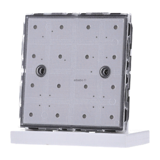
Structure of the device
(1) Supporting ring
(2) Box screws
(3) Frame
(4) Sensor module
(5) Plastic screws
(6) Insert for labelling
(7) Cover
Operation
Operation is through touching the respective sensor surface (button).
Operating blind/shutter
• Move blind/shutter: press and hold button
• Stop or adjust blind/shutter: press button briefly
(1)
(2)
(3)
(4)
Fig.1.: Structure of the device
2 x (5)
2 x (2)
(5)
(6)
(7)
Advertisement

Related Manuals for Jung SM 1608


Summary of Contents for Jung SM 1608
- Page 1 • Cloning: transfer of a set assignment to another sensor module. • If mains power fails, assignments are retained. • Easy installation through 2-wire cable. • Can be labelled using JUNG labelling tool. Structure of the device 2 x (5) 2 x (2) Fig.1.: Structure of the device...
- Page 2 Operating light (relay station) Switching: press button briefly (toggle mode) Operating light (dimming station) • Switching to switching-on brightness: press ON button briefly Pressing and holding the OFF button switches to minimum brightness. ⓘ Pressing and holding the ON button switches on and dims to maximum brightness. ⓘ...
-
Page 3: Programming Level
Fig.3.: Button assignment for connection to one station A1 - 8 and to 2 stations operated in parallel A1 - 16 The operation mode of the load outputs must be selected on the relay station in correspondence to the requirement ⓘ... - Page 4 Fig.4.: Numbering the buttons No switching commands are executed in the grouping mode. • Press buttons 6 – 3 – 5 – 5 in sequence (Figure 5). All LEDs fl ash 2x. • Press buttons 6 – 3 – 5 – 5 in sequence once again. All LEDs fl ash 2x.
- Page 5 Operating level is active. Button 2: Setting or changing the central function When assigning the central function, button 1 for central ON or button 2 for central OFF are selected, then the buttons which should switch the central function. It is also possible to assign only central ON or central OFF. Fig.6.: Installation Buttons 1 - 6 light up.
- Page 6 Free light scenes flash, assigned light scenes light continuously. • Select a light scene button 1 - 4. One LED lights up for each connected load output (1 - 8 or 1 - 16). The switching state of the respective load output is set by buttons. ⓘ...
- Page 7 ness in the switched-on and switched-off states. • Press button 4 (LED brightness) The link mode LED brightness is active. Assigned buttons flash 100 % off. Free buttons are off. • Set the LEDs by pressing the respective button 100 % off 50 - 100 % On - Off Off - 50 %...
-
Page 8: Technical Data
Buttons 1 - 6 light up. • Press button 6 (stations). The mode Stations is active. • To set the stations, press buttons as indicated in the table. Example: Device address 1 dimming station: button 2 Device address 2 relay station: button 5 •... -
Page 9: Warranty
Our products are under guarantee within the scope of the statutory provisions. Please send the device, postage paid, to our central Customer Service Centre, with a description of the error. ALBRECHT JUNG GMBH & CO. KG Service Centre Kupferstr. 17-19 44532 Lünen...
Need help?
Do you have a question about the SM 1608 and is the answer not in the manual?
Questions and answers