Table of Contents
Advertisement
Quick Links
Product documentation
Room controller display compact module 2-gang
Art. No. ..5192KRMTSD
Room controller display compact module 4-gang
Art. No. ..5194KRMTSD
ALBRECHT JUNG GMBH & CO. KG
Volmestraße 1
58579 Schalksmühle
GERMANY
Telefon: +49 2355 806-0
Issue: 15.04.2016
Telefax: +49 2355 806-204
TD 135579x0
kundencenter@jung.de
www.jung.de
Advertisement
Table of Contents

Related Manuals for Jung 5192KRMTSD Series


Summary of Contents for Jung 5192KRMTSD Series
- Page 1 Product documentation Room controller display compact module 2-gang Art. No. ..5192KRMTSD Room controller display compact module 4-gang Art. No. ..5194KRMTSD ALBRECHT JUNG GMBH & CO. KG Volmestraße 1 58579 Schalksmühle GERMANY Telefon: +49 2355 806-0 Issue: 15.04.2016 Telefax: +49 2355 806-204 TD 135579x0 kundencenter@jung.de...
-
Page 2: Table Of Contents
Product documentation Table of Contents Product definition ......................... Product catalogue ......................Function .......................... Accessories ........................Installation, electrical connection and operation .............. Safety instructions ......................Device components ......................2.2.1 Front view 2-gang ....................2.2.2 Front view 4-gang ....................2.2.3 Rear side ....................... - Page 3 Product documentation 4.2.4.3 Room temperature controller ................. 4.2.4.3.1 Operating modes and operating mode change-over ......4.2.4.3.2 Control algorithms and calculation of command values ....... 4.2.4.3.3 Adapting the control algorithms ............4.2.4.3.4 Operating mode switchover ..............4.2.4.3.5 Temperature setpoints ................4.2.4.3.6 Command value and status output ............
- Page 4 Product documentation Appendix ........................... Index ........................... Art. No. ..5192KRMTSD Page 4 of 309 Art. No. ..5194KRMTSD...
-
Page 5: Product Definition
Product definition 1 Product definition 1.1 Product catalogue Product name: Room controller display compact module 2-gang / Room controller display compact module 4-gang Use: Sensor Design: FM (flush-mounted) Art. No. ..5192KRMTSD / ..5194KRMTSD 1.2 Function The compact room controller module is a TSM (pushbutton sensor basic module). The TSM combines the functions of a KNX/EIB bus coupling unit, two single-room temperature controllers with setpoint specification, a pushbutton sensor (2-gang or 4-gang), and a display unit in just one KNX subscriber. - Page 6 Product definition For heating and cooling functions, you can select continuous or switching PI or switching 2-point feedback control algorithms. The controller distinguishes between different operating modes (comfort, standby, night, frost/heat protection) each with their own temperature setpoints for heating or cooling. Room temperature measurement: The product database of the device contains three independent blocks for room temperature measurement.
-
Page 7: Accessories
Product definition 1.3 Accessories Cover kit 2-gang Art. No. ..502 TSA.. Cover kit 4-gang Art. No. ..504 TSA.. Room controller extension module 2-gang Art. No. ..5178 TSEM Push-button extension module, 1-gang Art. No. ..5091 TSEM Push-button extension module, 2-gang Art. -
Page 8: Installation, Electrical Connection And Operation
Installation, electrical connection and operation 2 Installation, electrical connection and operation 2.1 Safety instructions Electrical devices may only be mounted and connected by electrically skilled persons. Failure to observe the instructions may cause damage to the device and result in fire and other hazards. -
Page 9: Device Components
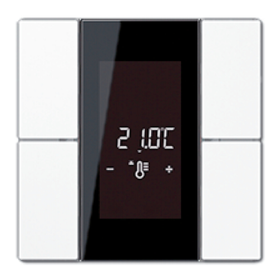
Installation, electrical connection and operation 2.2 Device components Device components of room controller display compact module The compact room controller module is available in the 2-gang and 4-gang variants. The device can be integrated into the switch programs A500, LS990 or CD500. Irrespective of the switch range, the devices make the same button and rocker functions, room temperature controller functions, disabling, scene and alarm signalling functions, as well as status LED functions, available. - Page 10 Installation, electrical connection and operation Figure 2: Front view of room controller display compact module 2-gang (Display: LS990 & CD500 switch range) (4) Display: LS990 & CD500 switch range Art. No. ..5192KRMTSD Page 10 of 309 Art. No. ..5194KRMTSD...
-
Page 11: Front View 4-Gang
Installation, electrical connection and operation 2.2.2 Front view 4-gang Device components of room controller display compact module 4-gang Figure 3: Front view of room controller display compact module 4-gang (Display: A500 switch range) (1) 8 control surfaces configurable as rocker 1...4 or as buttons 1…8 (2) 8 status LEDs (red, green, blue), can be freely configured (3) Display: A500 switch range Art. - Page 12 Installation, electrical connection and operation Figure 4: Front view of room controller display compact module 4-gang (Display: LS990 & CD500 switch range) (4) Display: LS990 & CD500 switch range i The room controller display compact module can be integrated into the switch programs A500, LS990 or CD500.
-
Page 13: Rear Side
Installation, electrical connection and operation 2.2.3 Rear side Device components of room controller display compact module rear side Figure 5: Rear side of room controller display compact module 2-gang/4-gang (5) Connection of push-button sensor extension module Alternatively: Connection of room controller extension module (6) Connection of remote sensor (external sensor) (7) Connection of KNX bus cable Art. -
Page 14: Mounting And Electrical Connection
Installation, electrical connection and operation 2.3 Mounting and electrical connection DANGER! Electrical shock on contact with live parts in the installation environment. Electrical shocks can be fatal. Before working on the device, disconnect the power supply and cover up live parts in the working environment. - Page 15 Installation, electrical connection and operation (14) KNX device connection terminal (15) TSEM device connection terminal Mount supporting frame (8) in the right orientation on an appliance box. Note the TOP marking. Use the enclosed box screws (13). Position the design frame (9) on the supporting frame. Connect the room controller display compact module (10) with KNX device connection terminal (14), which is connected to the KNX bus line, on the rear side of the module.
- Page 16 Installation, electrical connection and operation Figure 7: Connection of push-button sensor extension module Alternatively: Room controller extension module (rear view) (10) Room controller display compact module (14) KNX device connection terminal (15) Connection terminal for connecting an extension module to TSM, white-yellow (16) Connection line for extension module (17) Terminal for extension module on TSEM, white-yellow (18) Push-button sensor extension module...
- Page 17 Installation, electrical connection and operation Figure 8: Mounting the compact room controller module with connection of an extension module (8) Supporting frame (9) Design frame (10) Room controller display compact module (11) Fastening screws (12) Design control surfaces (13) Box screws (14) KNX device connection terminal (15) TSEM device connection terminal (16) Connection line for TSEM...
- Page 18 Installation, electrical connection and operation Fix push-button sensor module to supporting frame using the supplied plastic screws (11). Tighten the plastic screws only lightly. Installing the decorative control surfaces Place the Design control surfaces individually on the device. For the arrangement of the Design control surfaces, see "Device components"...
-
Page 19: Commissioning
Installation, electrical connection and operation 2.4 Commissioning After connection and mounting, the room controller display compact module can be put into operation. The commissioning is basically confined to programming with the ETS and attaching the decorative control surfaces. i The extension module does not receive any physical address of its own. It is activated by the application program loaded in the TSM. - Page 20 Installation, electrical connection and operation i To exclude any inadvertent activation of Programming mode during 'normal' use of the control surface in later operation, the time between the first and the second actuation must be at least 200 ms. Pressing simultaneously (time between first and second actuation <...
-
Page 21: Operation
Installation, electrical connection and operation 2.5 Operation The device possesses 8 mechanically separated pushbutton elements. The control surfaces are the pushbutton elements combined under an attached design cover. Irrespective of the device variant, the device always possesses eight pushbutton elements. In the 2-gang device variant, 2 pushbutton elements are always combined to form a control surface. -
Page 22: Operating Level
Installation, electrical connection and operation can function as an operation display or as a status display. Furthermore, different statuses of the internal controller can be displayed. As an alternative, with the aid of separate communication objects, they can signal widely varying display information completely independently of the pushbutton function, e.g. -
Page 23: Menu Level
Installation, electrical connection and operation 2.5.2 Menu level The menu level makes it possible to make various basic settings on the unit locally without using the ETS. In order to avoid the unintentional disruption of essential functions, access to individual settings or to the entire menu level can be prevented via the parameterisation in the ETS. - Page 24 Installation, electrical connection and operation (c) Negative value adjustment (d) Jump to the next menu entry i Continuous adjustment of the value settings is possible if buttons 1 or 2 are held in the depressed position. Project design in the ETS offers various options for influencing the entries that are visible and changeable in the menu: 1.
- Page 25 Installation, electrical connection and operation Only display of the actual temperature received via object. No adjustment possibility. The menu entry "Actual temperature" is visible as an option. Indication of setpoint temperature: Figure 15: Indication of setpoint temperature Only display of the setpoint temperature received via object. No adjustment possibility. The menu entry "Setpoint temperature"...
- Page 26 Installation, electrical connection and operation Figure 18: Display for recalling the Controller 1 and 2 submenu Display of the Controller 1 and Controller 2 submenu. Actuating button 2 jumps to this submenu. The menu entry "Controller n submenu" is visible as an option. Display for recalling the display settings: Figure 19: Display for recalling the display settings Display of the submenu of the display settings.
- Page 27 Installation, electrical connection and operation (see chapter 4.2.4.3.5. Temperature setpoints) The menu entry "Basic temperature / comfort temperature" is visible as an option as a component of the Controller n submenu. The editing function can be disabled separately. This menu is not accessible in controller extensions.
- Page 28 Installation, electrical connection and operation Figure 23: Setting the setpoint temperature "Lowering for night mode, heating" The + and - buttons can be used to adjust the temperature decrease for night mode for heating with a step width of +/- 0.1 K. The icons and are illuminated in the display. The temperature decrease is displayed flashing as a relative value in K.
- Page 29 Installation, electrical connection and operation Figure 25: Setting presence mode A "P" is shown in the display to indicate that the presence mode can be edited. "P 0" displays that no presence is active. "P 1" stands for active presence. The icons additionally shown in the display identify the active operating mode of the internal room temperature controller.
- Page 30 Installation, electrical connection and operation Figure 26: Setting the setpoint shift The menu entry for setpoint shifting is indicated in the display by the bar scale "- - - -·- - - -". The buttons + and - can be used to adjust the basic setpoint shift by up to 4 levels. Here the shift is shown in the display as a relative numeric value in kelvin (K) The step width of the shift depends on the ETS parameter "Increment of the 4-level setpoint shift"...
- Page 31 Installation, electrical connection and operation window status) has been specified by the controller.(see chapter 4.2.4.3.4. Operating mode switchover). The operating mode set in the menu level is only accepted by the controller when the operating mode with a higher priority has been terminated and in the meantime no other operating mode specification with a higher priority has been performed (e.g.
- Page 32 Installation, electrical connection and operation Recall the display pixel text ("Display settings" submenu): Figure 29: Pixel text in the design ranges LS and CD All the segments are switched on in the display. The view to be expected in the design ranges LS and CD during the pixel test is shown (figure 29)above.
- Page 33 Installation, electrical connection and operation Figure 31: Setting the display brightness "H" and the brightness value of the backlighting are displayed in the backlighting. The buttons + and - can be used to adjust the brightness of the display in the range from 5 to 100%. For additional notes about control of the backlighting, via the menu level, please see the chapter "Display control"...
- Page 34 Installation, electrical connection and operation Figure 33: Exiting the menu without saving "ESC" is shown on the display. Button 2 can be used to exit the menu level without saving the settings (see "Exiting the menu level"). This option is always visible. i All menu entries are displayed or not depending on the configuration of the ETS.
- Page 35 Installation, electrical connection and operation Automatic exiting: Automatic exiting of the menu level can optionally be configured in the ETS using the parameter of the same name in the parameter branch "General -> Basic settings -> Menu level". In this case the device leaves the menu level when no additional operation takes place after the last push-button operation within the "Time until automatic manu level exit"...
-
Page 36: Technical Data
Technical data 3 Technical data General Protection class Test mark KNX/EIB Ambient temperature -5 ... +45 °C Storage/transport temperature -25 ... +70 °C KNX/EIB supply KNX medium Commissioning mode S-mode Rated voltage KNX DC 21 ... 32 V SELV Current consumption KNX without TSEM max. -
Page 37: Software Description
Software specification 4 Software description 4.1 Software specification ETS search paths: - Heating, A/C, Ventilation / Regulator / Room controller display compact module 2-gang - Push-button / Push-button, general / Room controller display compact module 2-gang - Heating, A/C, Ventilation / Regulator / Room controller display compact module 4-gang - Push-button / Push-button, general / Room controller display compact module 4-gang... -
Page 38: Software "Room Controller Display Compact Module 146X11
Software "Room controller display compact module 146x11" Scope of functions 4.2 Software "Room controller display compact module 146x11" 4.2.1 Scope of functions General functions The backlighting can be switched permanently on or off. It can be switched on with a button-press, be switched on during night operation or be switched by a communication object. - Page 39 Software "Room controller display compact module 146x11" Scope of functions Functions of the integrated room temperature controller Parallel operation of both controllers is possible. Function buttons for operation of the room temperature controller. Various operating modes can be activated: Comfort, Standby, Night and Frost/heat protection Each operating mode can be assigned its own temperature-setpoints (for heating and/or cooling).
- Page 40 Software "Room controller display compact module 146x11" Scope of functions The actual and setpoint temperatures can be output on the bus if a configurable deviation is detected (also periodically). Separate or shared command value output in heating and cooling mode. This produces one or two command value objects for each level.
- Page 41 Software "Room controller display compact module 146x11" Scope of functions For the rocker functions Dimming, Venetian blind (operation concept "Long – Short or Short") and 2-channel operation, full-surface rocker operation can also be evaluated. With full-surface operation, switching telegrams and scene recall requests can be triggered on the KNX in addition to and independently of the configured rocker function.
- Page 42 Software "Room controller display compact module 146x11" Scope of functions When a status LED is internally connected with the rocker or the button, it can signal a button-press or the current status of a communication object. The status indication can also be in inverted form.
-
Page 43: Notes On Software
Software "Room controller display compact module 146x11" Notes on software 4.2.2 Notes on software ETS project design and commissioning Project design and commissioning of the device with the following ETS versions: ETS4.2 ETS5 or higher The necessary product database is offered in the *.knxprod format. No product database is available for ETS2, ETS3 and older versions of ETS4. -
Page 44: Object Table
Software "Room controller display compact module 146x11" Object table 4.2.3 Object table Number of communication objects Max. 195 objects (4-gang variants with extension module) Number of addresses (max.): Number of assignments (max.): 4.2.3.1 Rockers or button functions Function: Switching Object Function Name Type... - Page 45 Software "Room controller display compact module 146x11" Object table Function: Venetian blind Object Function Name Type Flag 1, 2, Short time operation Rocker/button 1 1-bit 1,007 C, -, -, T, - 3, 9, ...16 Description 1-bit object for the transmission of telegrams with which a Venetian blind or shutter drive motor can be stopped or with which the blind slats can be adjusted by short time operation.
- Page 46 Software "Room controller display compact module 146x11" Object table Function: 2-byte value transmitter Object Function Name Type Flag 1, 2, Temperature value Rocker/button 1 2 byte 9,001 C, (R), W, 3, 9, T, - ...16 Description 2 -byte object for the transmission of a temperature value from 0 °C to 40 °C. If the adjustment of the value is enabled, the object can transmit telegrams cyclically after a long press with which the value can be reduced or increased by 1 K.
- Page 47 Software "Room controller display compact module 146x11" Object table Function: 2-channel operation Object Function Name Type Flag 1, 2, Channel 1 value Rocker/button 1 1 byte 5.xxx C, -, -, T, - 3, 9, ...16 Description 1-byte object to transmit value telegrams. This object is enabled if 2-channel operation is activated with the function "Value transmitter 0...255 (1-byte)"...
- Page 48 Software "Room controller display compact module 146x11" Object table Function: 2-channel operation Object Function Name Type Flag Channel 2 temperature value Rocker/button 1 2 byte 9,001 C, -, -, T, - ...34 Description 2-byte object to transmit value telegrams. This object is enabled if 2-channel operation is activated with the function "Temperature value transmitter (2-byte)"...
-
Page 49: Status Led
Software "Room controller display compact module 146x11" Object table 4.2.3.2 Status LED Function: Status LED (control via separate LED object) Object Function Name Type Flag Switching Status LED 1 1-bit 1.xxx C, (R), W, -, - ...52 Description 1-bit object for activation of the status LED. Function: Status LED (operating mode display, comparator) Object... - Page 50 Software "Room controller display compact module 146x11" Object table Function: Separate control of status LED green Object Function Name Type Flag 108, Switching colour green Status LED 1 1-bit 1,001 C, (R), W, -, - Description 1-bit object for activation of the green status LED. This object is enabled when "3-colour individual control via objects"...
-
Page 51: Disabling Functions
Software "Room controller display compact module 146x11" Object table 4.2.3.3 Disabling functions Function: Switching Object Function Name Type Flag Switching Disabling function 1-bit 1.xxx C, (R), W, 1 / 2 T, - Description 1-bit object for transmission of switching telegrams (ON, OFF). Function: Dimming Object... - Page 52 Software "Room controller display compact module 146x11" Object table Function: 1-byte value transmitter Object Function Name Type Flag Value Disabling function 1 byte 5.xxx C, (R), W, 1 / 2 T, - Description 1-byte object for the transmission of values from 0 to 255 (corresponding to values from 0 % to 100 %).
- Page 53 Software "Room controller display compact module 146x11" Object table Function: 2-channel operation Object Function Name Type Flag Channel 1 switching Disabling function 1-bit 1.xxx C, (R), W, 1 / 2 T, - Description 1-bit object for the transmission of switching telegrams, if 2-channel operation is activated.
- Page 54 Software "Room controller display compact module 146x11" Object table Function: Disabling function Object Function Name Type Flag Disabling Button disabling 1-bit 1,001 C, (R), W, -, - Description 1-bit object by means of which the buttons can be disabled and enabled again (polarity configurable).
-
Page 55: Display
Software "Room controller display compact module 146x11" Object table 4.2.3.4 Display Function: Backlighting Object Function Name Type Flag Backlighting On/Off D.Input 1-bit 1,001 C, R, W, -, Description 1-bit object for switching the backillumination of the LC display (polarity configurable). Function: Backlighting Object... - Page 56 Software "Room controller display compact module 146x11" Object table Function: Temperature display Object Function Name Type Flag Display of setpoint D.Input 2 byte 9,001 C, -, W, -, - temperature Description 2-byte object for receiving a setpoint temperature. The setpoint temperature can be shown on the display.
- Page 57 Software "Room controller display compact module 146x11" Object table Function: Recalling display information Object Function Name Type Flag Cycl. Disable change of D.Input 1-bit 1,001 C, -, W, -, - display information Description 1-bit object, using which the cyclical change of the display information can be disabled.
-
Page 58: Alarm Signal
Software "Room controller display compact module 146x11" Object table 4.2.3.5 Alarm signal Function: Alarm signal Object Function Name Type Flag Switching Alarm signal 1-bit 1.xxx C, (R), W, -, - Description 1-bit object for the reception of an alarm signalling (polarity configurable). Function: Alarm signal Object... -
Page 59: Room Temperature Measurement
Software "Room controller display compact module 146x11" Object table 4.2.3.6 Room temperature measurement Function: Room temperature measurement Object Function Name Type Flag Measured value S. Temperature 2 byte 9,001 C, (R), -,T, TSM output Description 2-byte object for the display of the determined actual temperature. The actual temperature is either determined by the internal sensor, a received temperature value or by a combination of both measurement methods. - Page 60 Software "Room controller display compact module 146x11" Object table Function: Room temperature measurement Object Function Name Type Flag Measured value S. Temperature 2 byte 9,001 C, (R), -,T, TSEM output Description 2-byte object for the display of the determined actual temperature. The actual temperature is either determined by the internal sensor, a received temperature value or by a combination of both measurement methods.
- Page 61 Software "Room controller display compact module 146x11" Object table Function: Room temperature measurement Object Function Name Type Flag Measured value S. Temperature 2 byte 9,001 C, (R), -,T, RS output Description 2-byte object for the display of the determined actual temperature. The actual temperature is either determined by the internal sensor, a received temperature value or by a combination of both measurement methods.
-
Page 62: Scene Function
Software "Room controller display compact module 146x11" Object table 4.2.3.7 Scene function Function: Scene function Object Function Name Type Flag 82...- Switching Scene output 1 1-bit 1.xxx C, (R), W, T, A Description 1-bit objects for controlling up to eight actuator groups (ON, OFF). Function: Scene function Object... -
Page 63: Room Temperature Controller
Software "Room controller display compact module 146x11" Object table 4.2.3.8 Room temperature controller Objects for Controller 1 and Controller 2. Both controllers possess the same communication objects, meaning that the controller objects are only documented once for both controllers (First object number = Controller 1; second object number = Controller 2). - Page 64 Software "Room controller display compact module 146x11" Object table Function: Operating mode switchover Object Function Name Type Flag 158, Comfort mode C.Input 1-bit 1,001 C, (R), W, T, - Description 1-bit object for change-over to the "Comfort" operating mode. This object is only available in this way when the operating mode change-over is to take place over 4 x 1 bit (parameter-dependent).
- Page 65 Software "Room controller display compact module 146x11" Object table Function: Operating mode change-over presence detection Object Function Name Type Flag 163, Presence object C.Input / Output 1-bit 1,001 C, (R), W, T, - Description 1-bit object through which a presence detector or an external presence button (e.g.
- Page 66 Software "Room controller display compact module 146x11" Object table Object for controller status Function: Status signal Object Function Name Type Flag 166, Controller status C.Output 1 byte C, (R), -,T, Description 1-byte object used by the controller to output the current state of operation (e.g.
- Page 67 Software "Room controller display compact module 146x11" Object table Function: Status signal Object Function Name Type Flag 185, KNX status forced oper. C.Output 1 byte 20,102 C, (R), -,T, mode Description 1-byte object used by the controller to output the operating mode in the event of forced position.
- Page 68 Software "Room controller display compact module 146x11" Object table Function: Disable controller Object Function Name Type Flag 171, Disable additional level C.Input 1-bit 1,001 C, (R), W, -, - Description 1-bit object for deactivating the additional level of the controller. Polarity: Additional level deactivated = "1", additional level activated = "0".
- Page 69 Software "Room controller display compact module 146x11" Object table Function: Command value Object Function Name Type Flag 172, Command value for C.Output 1 byte 5,001 C, (R), -,T, heating/cooling / command value, basic level Description 1-byte object to output the combined continuous command value of the heating and cooling mode.
- Page 70 Software "Room controller display compact module 146x11" Object table Function: Command value Object Function Name Type Flag 173, Cmd. value, add. heating C.Output 1-bit 1,001 C, (R), -,T, (PWM) Description 1-bit object to output the continuous PWM command value for additional heating in two-level operation.
- Page 71 Software "Room controller display compact module 146x11" Object table Object for command value output, cooling Function: Command value Object Function Name Type Flag 174, Command value for cooling / C.Output 1 byte 5,001 C, (R), -,T, command value, basic cooling Description 1-byte object to output the continuous command value of the cooling mode.
- Page 72 Software "Room controller display compact module 146x11" Object table Function: Command value Object Function Name Type Flag 175, Cmd. value, add. cooling C.Output 1-bit 1,001 C, (R), -,T, (PWM) Description 1-bit object to output the continuous PWM command value for additional cooling in two-level operation.
- Page 73 Software "Room controller display compact module 146x11" Object table Object for additional command value output, PWM additional heating and combined valve PWM additional heating/cooling Function: Command value Object Function Name Type Flag 177, PWM cmd. value, add. C.Output 1 byte 5,001 C, (R), -,T, heating...
- Page 74 Software "Room controller display compact module 146x11" Object table Object for additional command value output, PWM additional cooling Function: Command value Object Function Name Type Flag 179, PWM cmd. value, add. C.Output 1 byte 5,001 C, (R), -,T, cooling Description 1-byte object to output the internal continuous command value of a PWM feedback controller for additional cooling in two-level operation.
- Page 75 Software "Room controller display compact module 146x11" Object table Function: Basic setpoint shifting Object Function Name Type Flag 183, Preset setpoint shifting C.Input 1 byte 6,010 C, (R), W, -, - Description 1-byte object for setting a basic setpoint shifting, e.g. via a controller extension.
- Page 76 Software "Room controller display compact module 146x11" Object table Function: Fan controller Object Function Name Type Flag 189, Ventilation, fan level 1 C.Output 1-bit 1,001 C, R, -,T, - Description 1-bit object for switching activation of the first fan level. This object is only available in this way when the fan control is to take place over 3 x 1 bit and at least one fan level is enabled (parameter-dependent).
- Page 77 Software "Room controller display compact module 146x11" Object table Function: Fan controller Object Function Name Type Flag 194, Ventilation, fan level 6 C.Output 1-bit 1,001 C, R, -,T, - Description 1-bit object for switching activation of the sixth fan level. This object is only available when the fan control is to take place over 3 x 1 bit and at least six fan levels are enabled (parameter-dependent).
- Page 78 Software "Room controller display compact module 146x11" Object table Function: Fan controller Object Function Name Type Flag 199, Ventilation, fan protection C.Input 1-bit 1,001 C, (R), W, -, - Description 1-bit object for activating the fan protection. Polarity: Fan protection ON = "1" / Fan protection OFF = "0". Function: Fan controller Object...
- Page 79 Software "Room controller display compact module 146x11" Object table Object for limiting the floor temperature Function: Floor temperature limitation Object Function Name Type Flag 203, Floor temperature C.Input 2 byte 9,001 C, (R), W, -, - Description 2-byte object for coupling an external temperature sensor for floor temperature limitation.
-
Page 80: Controller Extension
Software "Room controller display compact module 146x11" Object table 4.2.3.9 Controller extension Objects for Controller extension 1 and Controller extension 2. Both controller extensions possess the same communication objects, meaning that the controller extension objects are only documented once for both controllers (First object number = Controller extension 1;... - Page 81 Software "Room controller display compact module 146x11" Object table Function: Controller extension Object Function Name Type Flag Current setpoint shifting RNSTn.Button fct. 1 byte 6,010 C, (R), W, Input -, A Description 1-byte object used by the extension unit for receiving the current setpoint shift of the room temperature controller.
- Page 82 Software "Room controller display compact module 146x11" Object table Function: Controller extension Object Function Name Type Flag 178, Command value for cooling RNSTn.Display fct. 1 byte 5,001 C, -,W, -, 0%...100% Input Description 1-byte object to output the continuous command value of the cooling mode. In two-level cooling mode, command value output for the basic cooling.
- Page 83 Software "Room controller display compact module 146x11" Object table Function: Controller extension Object Function Name Type Flag 200, Ventilation visualisation RNSTn.Display fct. 1 byte 5,010 C, -,W, -, Input Description 1-byte object for additional value-guided acknowledgement of the active fan level.
-
Page 84: Operation Led And Labelling Field Illumination
Software "Room controller display compact module 146x11" Object table 4.2.3.10 Operation LED and labelling field illumination Function: Operation LED Object Function Name Type Flag Switching TSEM.Operation 1-bit 1,001 C, W, -, (R) Description 1-bit object for switching the operation LED of the connected TSEM on or off ("1"... -
Page 85: Functional Description
Software "Room controller display compact module 146x11" Functional description 4.2.4 Functional description 4.2.4.1 General settings 4.2.4.1.1 Button configuration The compact room controller module can be extended to 16 control surfaces using a pushbutton or room controller extension module, if necessary. An extension module expands the number of control surfaces in addition to the control surfaces of the basic unit, so that up to four rockers or 8 buttons more are available. -
Page 86: Operation Concept And Button Evaluation
Software "Room controller display compact module 146x11" Functional description 4.2.4.1.2 Operation concept and button evaluation The changeover between rockers and button operation of a control surface of the basic or extension module is made on the parameter pages "TSM operation concept" and "TSEM operation concept". -
Page 87: Transmission Delay
Software "Room controller display compact module 146x11" Functional description 4.2.4.1.3 Transmission delay After a reset (e.g. after loading of an application program or the physical address or after switch- on of the bus voltage), the device can automatically transmit telegrams for the "Room temperature controller extension"... -
Page 88: Display
Software "Room controller display compact module 146x11" Functional description 4.2.4.2 Display Introduction On the front side of the device, between the control surfaces, there is a LC display (LCD = Liquid crystal display) with switchable backlighting. On the display, icons signal various operating states of the integrated room temperature controller or the controller extension. - Page 89 Software "Room controller display compact module 146x11" Functional description Ľ "Frost/heat protection" operating mode active. Flashes on frost alarm. Frost alarm is dependent on an active "Controller status": - For "KNX-conformant" ("Frost protection setpoint (°C) fallen below), - For "General controller" (T <= +5 °C / +41 °F), Room - For "Transmit individual state"...
- Page 90 Software "Room controller display compact module 146x11" Functional description Figure 35: Possible display information of the display (19) Display 1: Display information "Actual temperature (via object)" (20) Display 2: Display information "Setpoint temperature (via object)" (21) Display 3: Display information "Outdoor temperature (via object)" (22) Display 4: Display information "Any temperature 1"...
- Page 91 Software "Room controller display compact module 146x11" Functional description Figure 36: Possible display information of the display (25) Display 7: Display information "Controller 1: Actual temperature + icons" (26) Display 8: Display information "Controller 1: Setpoint temperature + icons" (27) Display 9: Display information "Controller 1: Outdoor temperature + icons" (28) Display 10: Display information "Controller 1: Any temperature 1 + icons"...
- Page 92 Software "Room controller display compact module 146x11" Functional description shows "--.-" until a telegram is received. If configured, any temperature will only be read on the display and cannot be used for any further temperature or variable calculation in the controller. The temperatures can be indicated in °C or alternatively in °F.
-
Page 93: Display Control
Software "Room controller display compact module 146x11" Functional description 4.2.4.2.2 Display control Change-over of the display Up to 17 pieces of display information (actual temperature, setpoint temperature, outdoor temperature, any temperature) can be optionally displayed on the LC display of the device with the room temperature controller icons. - Page 94 Software "Room controller display compact module 146x11" Functional description Backlighting The display of the device has white backlighting that can be switched or dimmed. The function of the backlighting is specified in the parameter of the same name in the "Display" parameter node in the ETS.
- Page 95 Software "Room controller display compact module 146x11" Functional description i The brightness of the LCD backlighting in the switched-on state (always on, through button- press, night mode or 1-bit object) and the display contrast can be set locally on the device in the menu level (see chapter 2.5.2.
-
Page 96: Button Function Icons
Software "Room controller display compact module 146x11" Functional description 4.2.4.2.3 Button function icons Button function icons (only in the design ranges LS and CD!) can support the user of the device in the operation of button and rocker functions by visualising the button function. Up to eight button function icons can be configured in the ETS. - Page 97 Software "Room controller display compact module 146x11" Functional description Figure 40: Button function icons: Segment e and f Figure 41: Button function icons: Segment g, h and i i To activate an '+' icon, segments g, h and i can jointly be switched to visible. The defined button function icons are shown statically on the display.
-
Page 98: Room Temperature Controller
Software "Room controller display compact module 146x11" Functional description 4.2.4.3 Room temperature controller The device unites two independent room temperature controllers (Controller 1 and Controller 2). Each controller is an independent function section of the device and has its own parameter and object range in the ETS. - Page 99 Software "Room controller display compact module 146x11" Functional description "Heating and cooling" mixed operating mode In the "Heating and cooling" mixed operating mode, the controller is capable of triggering heating and cooling systems. In this connection, you can set the change-over behaviour of the operating modes...
- Page 100 Software "Room controller display compact module 146x11" Functional description "Change-over between heating and cooling" parameter in the "Room temperature control - > Controller general -> Setpoints" parameter branch set to "Via object". In this case, the operating mode is controlled via the object "Heating/cooling change-over", irrespective of the deadband.
-
Page 101: Control Algorithms And Calculation Of Command Values
Software "Room controller display compact module 146x11" Functional description 4.2.4.3.2 Control algorithms and calculation of command values Introduction To facilitate convenient temperature control in living or business spaces a specific control algorithm which controls the installed heating or cooling systems is required. Taking account of the preset temperature setpoints and the actual room temperature, the controller thus determines command values which trigger the heating or the cooling system. - Page 102 Software "Room controller display compact module 146x11" Functional description control algorithms in two-level heating and cooling operation. The command values calculated by the control algorithm are output via the "Heating command value" or "Cooling command value" communication objects. Depending on the control algorithm selected for the heating and/or cooling mode, the format of the command value objects is, among other things, also specified.
- Page 103 Software "Room controller display compact module 146x11" Functional description changing the duty factor of the switch-on and switch-off pulses of the command value signal. The duty factor will be adapted by the regulator only at the end of a time period, depending on the variable calculated.
- Page 104 Software "Room controller display compact module 146x11" Functional description During cycle time configuration, a distinction can always be made between two cases... Case 1: Cycle time > 2 x adjusting cycle time of the electrothermal drives used (ETD) In this case, the switch-on or switch-off times of the PWM signal are long enough for the actuators to have sufficient time to fully open or fully close within a given time period.
- Page 105 Software "Room controller display compact module 146x11" Functional description The room temperature is also evaluated by this type of control in cycles every 30 seconds. Thus the command values change, if required, only at these times. The disadvantage of a continuously varying temperature as a result of this feedback control option is in contrast with the advantage of this very simple 2-point room temperature control.
- Page 106 Software "Room controller display compact module 146x11" Functional description Figure 46: 2-point feedback control for the single "Cooling" operating mode An additional 2-point feedback control heating or cooling level works exactly the same as the 2-point feedback control of the basic level. The difference is that the setpoint and the hysteresis values will shift by taking into account the configured level offset.
- Page 107 Software "Room controller display compact module 146x11" Functional description The following two images show 2-point feedback control for the mixed operating mode "Heating and cooling", distinguishing between heating mode (figure 47) and cooling mode (figure 48). The images take two temperature setpoints, a non-inverted command value output and an automatic operating mode change-over.
- Page 108 Software "Room controller display compact module 146x11" Functional description An additional 2-point feedback control heating or cooling level works exactly the same as the 2-point feedback control of the basic level. The difference is that the setpoint and the hysteresis values will shift by taking into account the configured level offset.
-
Page 109: Adapting The Control Algorithms
Software "Room controller display compact module 146x11" Functional description 4.2.4.3.3 Adapting the control algorithms Adapting the PI control There are several systems available, which may heat or cool a room. One option is to uniformly heat or cool the surroundings via heat transfer media (preferably water or oil) in connection with room air convection. - Page 110 Software "Room controller display compact module 146x11" Functional description Table 4: Predefined control parameters and recommend control types for cooling systems If the "Type of heating" or "Type of cooling" parameters are set to "Via control parameters" it will be possible to adjust the control parameter manually. The feedback control may be considerably influenced by presetting the proportional range for heating or for cooling (P component) and the reset time for heating or for cooling (I component).
- Page 111 Software "Room controller display compact module 146x11" Functional description Adapting the 2-point feedback control 2-point feedback control represents a very simple temperature control. For this type of feedback control, two hysteresis temperature values are set. The upper and lower temperature hysteresis limits can be adjusted via parameters.
-
Page 112: Operating Mode Switchover
Software "Room controller display compact module 146x11" Functional description 4.2.4.3.4 Operating mode switchover Introduction - The operating modes The room temperature controller has various operating modes. The selection of these modes will, for example, facilitate the activation of different temperature setpoints, depending on the presence of a person, on the state of the heating or cooling system, on the time of the day, or on the day of the week. - Page 113 Software "Room controller display compact module 146x11" Functional description Frost/heat protection mode Ľ Frost protection will be required if, for example, the room temperature must not fall below critical values while the window is open. Heat protection can be required where the temperature rises too much in an environment which is always warm, mainly due to external influences.
- Page 114 Software "Room controller display compact module 146x11" Functional description button function of the TSM for the controller operating mode. The presence button means it is possible to change to the comfort extension or to deactivate it prematurely when Night or Frost/heat protection mode (not activated by the "Window status"...
- Page 115 Software "Room controller display compact module 146x11" Functional description Figure 52: Operating mode change-over through 4 x 1-bit objects with presence detector Object Object Object Object Object Motion Motion Resulting operating mode Ľ ļ Ļ ĺ "Window button detector status" Frost/heat protection Comfort mode Standby mode...
- Page 116 Software "Room controller display compact module 146x11" Functional description i When changing over the operating mode, the objects "Comfort mode", "Standby mode", "Night mode" and "Frost/heat protection" are updated by the controller and can be read out when the appropriate Read flags are set. If the "Transmit" flag has been set for these objects the current values will, in addition, be automatically transmitted to the bus when they are changed.
- Page 117 Software "Room controller display compact module 146x11" Functional description Figure 54: Operating mode change-over through KONNEX object with presence detector Object value Object value Object Resulting operating mode "Operating "Forced object "Windo- tion tion mode operating butto- detect- change-over" mode" status"...
- Page 118 Software "Room controller display compact module 146x11" Functional description Frost/heat protection Table 7: Status of the communication objects and the resulting operating mode X: Status irrelevant -: Not possible i When changing over an operating mode, for example through local control, the KONNEX switching object is updated by the controller and can be read out when the "Read"...
- Page 119 Software "Room controller display compact module 146x11" Functional description Additional information on the Presence function / Comfort extension With presence detection, the room temperature controller can quickly change over to a comfort extension upon push button actuation or go into the Comfort mode when movement by a person in the room is detected.
- Page 120 Software "Room controller display compact module 146x11" Functional description Additional information on the window status and the automatic frost protection The room temperature controller offers various options to change over into the Frost/heat protection mode. In addition to the switchover by the corresponding operating mode switchover object or by room temperature controller operation on the TSM (button function), the frost/heat protection mode can by activated by a window contact or, alternatively, frost protection can be activated by an automatic temperature control option.
- Page 121 Software "Room controller display compact module 146x11" Functional description i When a window is open or when the automatic frost protection is active, it is not possible to switch over the controller operating mode using buttons with the "Controller operation" function, and not in the menu for the settings.
-
Page 122: Temperature Setpoints
Software "Room controller display compact module 146x11" Functional description 4.2.4.3.5 Temperature setpoints Setpoint temperature presetting Temperature setpoints can be preset for each operating mode in the ETS as part of first configuration. It is possible to configure the setpoints for the "Comfort", "Standby" and "Night" modes directly (absolute setpoint presetting) or relatively (derivation from basic setpoint). - Page 123 Software "Room controller display compact module 146x11" Functional description i Since the setpoint shift option is not necessary when using the absolute setpoint presetting, the status LED function "Setpoint value shift display" is also ineffective. The temperature setpoints programmed in the room temperature controller by the ETS during commissioning can be changed via communication objects.
- Page 124 Software "Room controller display compact module 146x11" Functional description ≤ T Night setpoint heating Comfort setpoint heating The standby and night setpoint temperatures are derived from the reduction temperatures configured in the ETS from the comfort setpoint temperature (basic setpoint). The frost protection is supposed to prevent the heating system from freezing.
- Page 125 Software "Room controller display compact module 146x11" Functional description Figure 57: Setpoint temperatures in the operating mode "Cooling" The setpoint temperatures for comfort, standby and night mode exist for this operating mode. The heat protection temperature can be preset(figure 57). The following applies…...
- Page 126 Software "Room controller display compact module 146x11" Functional description ≤ T Comfort setpoint basic level heating Comfort setpoint additional level heating ≤ T Standby setpoint basic level heating Standby setpoint additional level heating ≤ T Comfort setpoint cooling Standby setpoint cooling ≤...
- Page 127 Software "Room controller display compact module 146x11" Functional description Figure 60: Setpoint temperatures in the operating mode "Heating and cooling" with asymmetrical deadband For this heating/cooling operating mode, the setpoint temperatures of both heating/cooling modes exist for the Comfort, Standby and Night operating modes as well as the deadband. A distinction is made in the deadband position with combined heating and cooling.
- Page 128 Software "Room controller display compact module 146x11" Functional description cooling mode. Figure 61: Setpoint temperatures in the operating mode "Basic and additional heating and cooling" with symmetrical deadband Art. No. ..5192KRMTSD Page 128 of 309 Art. No. ..5194KRMTSD...
- Page 129 Software "Room controller display compact module 146x11" Functional description Figure 62: Setpoint temperatures in the operating mode "Basic and additional heating and cooling" with asymmetrical deadband ≤ T ≤ T ≤ T Comfort setpoint add. level Heating Comfort setpoint basic level Heating Comfort setpoint basic level Cooling Comfort setpoint add.
- Page 130 Software "Room controller display compact module 146x11" Functional description deadband = "symmetrical" The deadband preset in the ETS is divided into two parts at the basic setpoint. The comfort setpoint temperatures are derived directly from the basic setpoint resulting from the half deadband.
- Page 131 Software "Room controller display compact module 146x11" Functional description Accept setpoints permanently If the basic setpoint has been modified by the communication objects "Basic setpoint" or "Setpoint of active operating mode", two possible cases can be distinguished, which are set by the parameter "Apply change of the setpoint of the basic temperature"...
- Page 132 Software "Room controller display compact module 146x11" Functional description i It has to be considered that a shift of the displayed setpoint temperature (temperature offset of the basic temperature) will directly affect the basic setpoint and as a result shift all other temperature setpoints.
- Page 133 Software "Room controller display compact module 146x11" Functional description Starting situation: current setpoint temperature = 21.0°C / Counter value in "Current setpoint shift" = "0" (no active setpoint shift) After the setpoint shifting: -> A setpoint shift by one temperature increment in the positive direction will count up the value in the "Current setpoint shift"...
- Page 134 Software "Room controller display compact module 146x11" Functional description The temporary setpoint display for setpoint shift is active. At the time the button is pressed for a setpoint shift the setpoint temperature is visible in the display via the cyclical change of the display information or via a previous "change in the display reading"...
- Page 135 Software "Room controller display compact module 146x11" Functional description i A setpoint shift does not affect the temperature setpoints for frost or heat protection! In the case of absolute setpoint presetting, a setpoint shift can only be performed on main controllers.
-
Page 136: Command Value And Status Output
Software "Room controller display compact module 146x11" Functional description 4.2.4.3.6 Command value and status output Command value objects The format of the command value objects are determined depending on the control algorithm selected for heating and / or cooling and, if applicable, also for the additional levels. 1 bit or 1 byte command value objects can be created in the ETS. - Page 137 Software "Room controller display compact module 146x11" Functional description -> inverted: Command value off / on, value 1 / 0 Automatic transmission On automatic transmission, a distinction is made with regard to the type of control... Continuous PI control: In case of a continuous PI control, the room temperature controller calculates a new command value periodically every 30 seconds and outputs it to the bus via a 1-byte value object.
- Page 138 Software "Room controller display compact module 146x11" Functional description Controller status The room temperature controller can transmit its current status to the KNX/EIB. A choice of data formats is available for this. The "Controller status" parameter in the "Room temperature control ->...
- Page 139 Software "Room controller display compact module 146x11" Functional description "Controller general": The general controller status collects essential status information of the controller in two 1-byte communication objects. The "Controller status" object contains fundamental status information (see Table 9). The "Status signal addition" object collects in a bit-orientated manner further information that is not available via the "Controller status"...
- Page 140 Software "Room controller display compact module 146x11" Functional description "Transmit individual state" The 1 bit status object "Controller status, ..." contains the status information selected by the "Single status" parameter. Meaning of the status signals: "Comfort mode active" -> Active if operating mode "Comfort " or a comfort extension "" is activated.
- Page 141 Software "Room controller display compact module 146x11" Functional description Presence (Presence detector) No presence (Presence detector) Presence (Presence button) No presence (Presence button) Window opened No window opened Additional level active Additional level inactive Heat protection active Heat protection inactive Controller disabled Controller not disabled (dew point operation)
- Page 142 Software "Room controller display compact module 146x11" Functional description As soon as the command value limit is active, calculated command values are limited according to the limiting values from the ETS. The behaviour with regard to the minimum or maximum command value is then as follows...
- Page 143 Software "Room controller display compact module 146x11" Functional description Special case for command value 100% (Clipping mode) If with a PI control the calculated command value of the controller exceeds the physical limits of the actuator, in other words if the calculated command value is greater than 100%, then the command value is set to the maximum value (100%) and thus limited.
- Page 144 Software "Room controller display compact module 146x11" Functional description Parameter description required project design Operating mode Heating and cooling Sending command value for heating and cooling to a shared object Type of control Continuous PI control Output of the command value Normal (under current, this means opened) Rotation angle conversion: required settings of the controller parameters...
- Page 145 Software "Room controller display compact module 146x11" Functional description Figure 63: Control ball valve - valve curve Immediately after processing the room temperature controller function, the conversion is carried out if the rotary angle output was enabled in the parameters of the database. The controller operating mode (heating and cooling) and the current command value as well as the configured rotary angles are included in the calculation of the rotary angle to be set.
-
Page 146: Fan Controller
Software "Room controller display compact module 146x11" Functional description 4.2.4.3.7 Fan controller Operating mode and fan levels The room temperature control can be supplemented with a fan controller. This makes it possible to control the fan from heating and cooling systems operated by circulating air, such as fan coil units (FanCoil units), depending on the command value calculated in the controller or using manual operation. - Page 147 Software "Room controller display compact module 146x11" Functional description Table 11: Value meaning for 1 byte fan level object Due to fan motors' inertia, as a rule there is a limit to how short the time intervals for switching the fan levels can be, i.e. there is a limit to how quickly the fan speed can be varied. Often the technical information for a fan coil unit specifies change-over times that the fan controller must maintain for each fan level change-over.
- Page 148 Software "Room controller display compact module 146x11" Functional description i The fans of a fan coil unit are - as described above - controlled by the fan level objects of the controller. The electromechanical valves for heating and/or cooling, integrated into the blower devices, can be activated via suitable switching actuators using the objects "Heating message"...
- Page 149 Software "Room controller display compact module 146x11" Functional description i In automatic mode, the fan level objects are updated according to the internal command value calculation (cyclically every 30 seconds) plus the waiting time configured for level change-over. Telegram transmission only takes place when the object values of the fan levels are changed.
- Page 150 Software "Room controller display compact module 146x11" Functional description Switch-on level The fan can, if it was switched off before and should now start up, be switched on at a defined switch-on level. This switch-on level can be any of the available fan levels, and is set in the ETS using the "Start-up via level"...
- Page 151 Software "Room controller display compact module 146x11" Functional description i The parameter "Start-up via level" is not checked for plausibility in the ETS, meaning that an incorrect configuration is possible. For this reason, care should be taken to ensure that there is no switch-on level in the configuration which is higher than the actual fan levels.
- Page 152 Software "Room controller display compact module 146x11" Functional description is configured, the controller will, when a button is pressed, switch to the switch-on level and remain there until further operation occurs. i The parameter "Behaviour in a forced position" is not checked for plausibility, meaning that an incorrect configuration is possible.
- Page 153 Software "Room controller display compact module 146x11" Functional description communication object. The reaction of the fan to switching fan protection depends on the operating mode of the automatic fan system. In automatic operation, the fan switches back to the level determined by the command value of the room temperature control.
-
Page 154: Disable Functions Of The Room Temperature Controller
Software "Room controller display compact module 146x11" Functional description 4.2.4.3.8 Disable functions of the room temperature controller Certain operation conditions may require the deactivation of the room temperature control. For example, the controller can be switched-off during the dew point mode of a cooling system or during maintenance work on the heating or cooling system. -
Page 155: Valve Protection
Software "Room controller display compact module 146x11" Functional description 4.2.4.3.9 Valve protection Valve protection may be carried out periodically in order to prevent the addressed control valves of the heater or cooling system from becoming calcified or stuck. When set to "Yes", the "Valve protection"... -
Page 156: Underfloor Heating Temperature Limit
Software "Room controller display compact module 146x11" Functional description 4.2.4.3.10 Underfloor heating temperature limit The temperature limit can be activated in the controller in order to protect an underfloor heating system. If the temperature limit is enabled in the ETS, the controller continuously monitors the floor temperature. -
Page 157: Controller Extension
Software "Room controller display compact module 146x11" Functional description 4.2.4.4 Controller extension The device unites two independent room temperature controllers (Controller 1 and Controller 2). Each controller is an independent function section of the device and has its own parameter and object range in the ETS. - Page 158 Software "Room controller display compact module 146x11" Functional description configuration of one control surface and if the controller extension function has been enabled on the "Room temperature control..." tab. In all other cases, controller extension operating does not function. In addition, the TSM can – even independently of the controller extension function – indicate the state of one or more room temperature controllers with the status LED.
- Page 159 Software "Room controller display compact module 146x11" Functional description i The actual room temperature can be detected by the communication objects of the room temperature measurement system, which are also available in the controller extension, and then shown in the display. Art.
-
Page 160: Operating Functions
Software "Room controller display compact module 146x11" Functional description 4.2.4.4.2 Operating functions Operating mode switchover Change-over of the controller operating mode can be effected in accordance with the standard function block for room temperature controllers defined in the KNX handbook with two 1-byte communication objects. - Page 161 Software "Room controller display compact module 146x11" Functional description Presence button All buttons with their function set to "Presence button" are internally linked with the "RNSTn.Button fct.Input/output presence button" object. The parameter "Presence function on pressing the button" defines the object value transmitted to the bus on pressing a button. In order to ensure that the object value transmitted in the "Presence TOGGLE"...
- Page 162 Software "Room controller display compact module 146x11" Functional description continue the adjustment anytime at the right point. The extension units can likewise react to a reset of the setpoint shifting function by the controller. Art. No. ..5192KRMTSD Page 162 of 309 Art.
-
Page 163: Display Functions
Software "Room controller display compact module 146x11" Functional description 4.2.4.4.3 Display functions Indication of the controller operating mode The controller extension can indicate the current operating mode of the controller in the display. Just like on the controller itself, the operating mode is indicated by the comfort ļ, standby Ļ, night ĺ... - Page 164 Software "Room controller display compact module 146x11" Functional description cooling. For the display to function, the communication objects for the controller command values of heating mode and/or cooling mode of the extension and main controller must be connected. The command value format are strongly dependent on the parameterisation of the main controller.
-
Page 165: Behaviour After A Device Restart
Software "Room controller display compact module 146x11" Functional description 4.2.4.4.4 Behaviour after a device restart The different indication and operating functions of the controller extension are controlled via different communication objects as described in the previous chapters. A main controller must transmit the current status to the extensions, i.e. -
Page 166: Room Temperature Measurement
Software "Room controller display compact module 146x11" Functional description 4.2.4.5 Room temperature measurement Basic principles The room temperature controller possesses an integrated temperature sensor, using which the room temperature can be detected. The TSEM offers a second option for room temperature measurement, as it also possesses an internal temperature sensor. - Page 167 Software "Room controller display compact module 146x11" Functional description Temperature detection and measured value formation The "Temperature detection by" parameter in the "Room temperature measurement -> ..." parameter node specifies the sensors to detect the room temperature. The following settings are possible for temperature detection: "internal temperature sensor"...
- Page 168 Software "Room controller display compact module 146x11" Functional description permanently below or above the actual temperature in the vicinity of the sensor. To determine the temperature deviation, the actual room temperature should be detected with a reference measurement using a calibrated temperature measuring device. The parameter "Internal sensor calibration..."...
-
Page 169: Rockers And Button Function
Software "Room controller display compact module 146x11" Functional description 4.2.4.6 Rockers and button function The following contains descriptions of the various functions that can be configured for each rocker or each button of the push-button sensor. The functions can be parameterized freely and without limitations for both the basic unit and for the push-button sensor extension module. -
Page 170: Dimming Function
Software "Room controller display compact module 146x11" Functional description 4.2.4.6.2 Dimming function For each rocker or each button with the function set to "dimming" the ETS indicates a 1-bit and a 4-bit object. Generally, the push-button sensor transmits a switching telegram after a brief press and a dimming telegram after a long press. - Page 171 Software "Room controller display compact module 146x11" Functional description operation is enabled, the device can make use of this time span to evaluate the otherwise invalid simultaneous actuation of both buttons of the rocker. Full-surface operation of a rocker switch is detected by the device when both buttons are pressed at the same time.
-
Page 172: Blind" Function
Software "Room controller display compact module 146x11" Functional description 4.2.4.6.3 "Blind" function For each rocker or each button with the function set to "blind" the ETS indicates the two 1-bit objects "STEP operation" and "MOVE operation". The status LEDs can be configured independently . (see chapter 4.2.4.7.1. Functions of the status LED). - Page 173 Software "Room controller display compact module 146x11" Functional description Figure 65: Operation concept "long – short" Operation concept "long – short": In the operation concept "short – long – short", the push-button sensor shows the following behaviour: Immediately on pressing the button, the push-button sensor transmits a long time telegram. The drive begins to move and time T1 ("slat adjusting time") is started.
- Page 174 Software "Room controller display compact module 146x11" Functional description Figure 67: Operation concept "long – short or short" Operation concept "long – short or short": In the operation concept "long – short or short", the push-button sensor shows the following behaviour: Immediately on pressing the button, the push-button sensor starts time T1 ("time between short and long time command") and waits.
- Page 175 Software "Room controller display compact module 146x11" Functional description Full-surface operation with Venetian blind function When a rocker is configured for Venetian blind operation and if the operation concept "long – short or short" is used, the push-button sensor needs some time at the beginning of each operation in order to distinguish between a short and a long operation.
-
Page 176: Value Transmitter" Function
Software "Room controller display compact module 146x11" Functional description 4.2.4.6.4 "Value transmitter" function For each rocker or each button with the function set to "1-byte value transmitter" or "2-byte value transmitter" the ETS indicates a corresponding object. On the press of a button, the configured value or the value last stored internally by a value change (see below) will be transmitted to the bus. - Page 177 Software "Room controller display compact module 146x11" Functional description 1-byte value transmitter 0...255 1-byte value transmitter 0...100 % 0 % (value = 0) 100 % (value = 255) 2-byte value transmitter 0...65535 65535 2-byte value transmitter Temperature value 0 °C 40 °C 2-byte value transmitter Brightness value 0 lux...
- Page 178 Software "Room controller display compact module 146x11" Functional description Figure 69: Example of value adjustment with value range overflow Art. No. ..5192KRMTSD Page 178 of 309 Art. No. ..5194KRMTSD...
-
Page 179: Scene Extension Function
Software "Room controller display compact module 146x11" Functional description 4.2.4.6.5 Scene extension function For each rocker or each button with the function set to "scene extension" the ETS indicates the "Function" parameter which distinguishes between the settings... "Scene extension without storage function", "Scene extension with storage function", "Recall internal scene without storage function"... -
Page 180: 2-Channel Operation Function
Software "Room controller display compact module 146x11" Functional description 4.2.4.6.6 2-channel operation function In some situations it is desirable to control two different functions with a single button-press and to transmit different telegrams, i.e. to operate two function channels at a time. This is possible with the "2-channel operation"... - Page 181 Software "Room controller display compact module 146x11" Functional description telegram has been transmitted, the status LED lights up for approx. 250 ms in the "Telegram acknowledge" setting. In this operation concept, the push-button sensor will not transmit a telegram immediately after the rocker has been depressed.
-
Page 182: Controller Extension Function
Software "Room controller display compact module 146x11" Functional description 4.2.4.6.7 Controller extension function i The "controller extension" function is purely a button function and thus is not available with the "rocker function" operation concept. For each button with the function set to "controller extension" the ETS indicates the "Function" parameter which distinguishes between the settings: "Operating mode switchover"... -
Page 183: Controller Operation Function
Software "Room controller display compact module 146x11" Functional description 4.2.4.6.8 Controller operation function i The "Controller operation" function is purely a button function and thus is not available with the "rocker function" operation concept. The "Controller operation" button function can be used to control the internal room temperature controller. - Page 184 Software "Room controller display compact module 146x11" Functional description either one of the above-mentioned modes is activated (single selection) on pressing the button, or the device is switched over between two or three modes (multiple selection). i If a status LED is to indicate the current operating mode, the status LED function must be programmed for "Operating mode indication"...
- Page 185 Software "Room controller display compact module 146x11" Functional description configured so that it is permanently on or off, the pressing of the button or the status of the switching object "fan control automatic or manual" does not display inverted or displays inverted.
-
Page 186: Change In The Display Reading" Function
Software "Room controller display compact module 146x11" Functional description 4.2.4.6.9 "Change in the display reading" function Up to 17 pieces of display information (actual temperature, setpoint temperature, outdoor temperature, any temperature) can be optionally displayed on the LC display of the device with the room temperature controller icons.(see chapter 4.2.4.2.1. -
Page 187: Status Led
Software "Room controller display compact module 146x11" Functional description 4.2.4.7 Status LED 4.2.4.7.1 Functions of the status LED Each control surface on the TSM or on the TSEM has a three-colour status LED. The functions available differ slightly depending on the settings of the rockers or buttons. i In order to keep the complexity of the ETS product database within limits, the ETS always offers all function settings for the status LED –... - Page 188 Software "Room controller display compact module 146x11" Functional description Status LED function "always OFF" or "always ON" With this parameterisation, a status LED remains permanently switched on or off. Function of the status LED "Button-press display" or "Telegram acknowledgement" A status LED used as button-press display is switched on by the sensor each time the corresponding rocker or button is pressed.
- Page 189 Software "Room controller display compact module 146x11" Functional description Function of status LED as "controller status display" If a status LED is to indicate the status of a room temperature controller, the room temperature controller function or controller extension must have been activated on the parameter page "room temperature controller..."...
- Page 190 Software "Room controller display compact module 146x11" Functional description Bit 1: Comfort mode extension Bit 2: Status of the presence detector ( presence = 1 / no presence = 0) Bit 3: Status of the presence button (presence = 1 / no presence = 0) Bit 4: Window status (Window open = 1 / Window closed = 0) Bit 5: Additional level active Bit 6: Heat protection active...
- Page 191 Software "Room controller display compact module 146x11" Functional description Function of the status LEDs "Setpoint value shift indicator", "Presence status indicator" and "Inverted presence status indicator": With these LED functions, too, the room temperature controller function or the controller extension must have been activated on parameter page "Room temperature controller..." in order for a status LED to indicate the setpoint shift or the presence status of a room temperature controller function.
- Page 192 Software "Room controller display compact module 146x11" Functional description The difference is as follows... All status LEDs have the same colour. If the common colour setting is desired, then the parameter "Colour of all status LEDs" on parameter page "Configuration..." must be parameterised to the settings "red", "green" or "blue".
- Page 193 Software "Room controller display compact module 146x11" Functional description i When the superposed function is activated via a 1-bit object it is possible to have the status LED flash in the superposed colour. During flashing the status LED switches cyclically between the "switched-on"...
-
Page 194: Standard Display Function
Software "Room controller display compact module 146x11" Functional description 4.2.4.7.2 Standard display function The room controller display compact module can be configured and put into operation without a great deal of project design work using a standard operating and display function. This function can be switched on or off using the parameter "Standard display function (TSM)"... - Page 195 Software "Room controller display compact module 146x11" Functional description Furthermore, the state of the selected status LED row can be configured in case the setpoint is not shifted (figure 75). Setpoint shifting display: 4 steps in each direction With the "4 steps per direction" display, all four right status LEDs of the selected side are allocated to the respective current state of the negative or positive adjustment.
- Page 196 Software "Room controller display compact module 146x11" Functional description increasing adjustment) from the centre outwards, depending on the direction of the adjustment. Figure 74: Standard display function: setpoint shift display "2 steps" Setpoint shift display: No adjustment During the standard display function, various types of display for displaying the state of the setpoint shift = 0, i.e.
- Page 197 Software "Room controller display compact module 146x11" Functional description i If the standard display function is enabled, the status LEDs of the selected side cannot be changed and are permanently assigned to the setpoint shift. Standard display funktion: temporary fan level display One function to be regarded as an extension of the LED function "Fan controller display"...
-
Page 198: Scene Function
Software "Room controller display compact module 146x11" Functional description 4.2.4.8 Scene function The room controller display compact module can be used in two different ways as part of a scene control system... Each rocker or button can work as a scene extension. This feature makes it possible to recall or to store scenes which may be stored in other devices (see chapter 4.2.4.6.5. - Page 199 Software "Room controller display compact module 146x11" Functional description The parameter "Transmit delay" permits entering an individual waiting time for each scene output. This transmit delay can be used in different situations... When the actuators participating in a scene transmit status messages automatically or when several scene buttons are used to increase the number of channels within the scenes, the recall of a scene may result for a short time in high bus loading.
- Page 200 Software "Room controller display compact module 146x11" Functional description Figure 76: Flow chart for the transmission delay of scene output When a new scene recall (also with the same scene number) occurs during a current scene recall - even in consideration of the pertaining transmit delays - the scene processing started first will be aborted and the newly received scene number will be processed.
- Page 201 Software "Room controller display compact module 146x11" Functional description serves this purpose. The precondition is that the scene output defined last is configured as "Scene extension" and connected with the object "Scenes - extension input" via a group address. Examples: A scene calls itself up recursively, by giving the value of the scene output configured as scene extension its own scene number.
-
Page 202: Disabling Function
Software "Room controller display compact module 146x11" Functional description 4.2.4.9 Disabling function Configuration With the 1-bit communication object "Disable buttons", the control surfaces on the TSM and TSEM can be partly or completely disabled. During a disable, the rockers or buttons cannot execute any functions or can execute, temporarily, another function. - Page 203 Software "Room controller display compact module 146x11" Functional description The device (TSM + TSEM) executes the function assigned to any "target button" in non- disabled state. Target buttons are operating buttons of the pushbutton sensor on the basic device as well as on the extension module, which may be configured for rocker or for button operation.
- Page 204 Software "Room controller display compact module 146x11" Functional description Controller operation Presence telegram No telegram Motion detection Controller operation Level value telegram No telegram Setpoint shift Controller operation Fan level telegram No telegram Fan controller No function No telegram No telegram Telegram reactions of the pushbutton sensor with respect to the target push-button function Set the parameter "Reaction of pushbutton sensor at the beginning / end of disabling"...
- Page 205 Software "Room controller display compact module 146x11" Functional description Only the individually specified buttons are locked during disabling. The other control buttons remain unaffected by disabling. The status LEDs of the disabled buttons are without function (no button-press display either). Only the "Always ON" or "Always OFF" state remains unaffected by the disabling function.
-
Page 206: Alarm Signal
Software "Room controller display compact module 146x11" Functional description 4.2.4.10 Alarm signal The device permits signalling of a alarm which might be, for instance, a burglar or a fire alarm from a KNX central alarm unit. The alarm is signalled by synchronous flashing of all the status LEDs of the compact room controller module. -
Page 207: Delivery State
Software "Room controller display compact module 146x11" Functional description 4.2.4.11 Delivery state The delivery state defines the functions of the device when it is connected to the KNX but has not been programmed with application data by the ETS. This condition persists until the application is programmed into the device. The text NEU appears in the device display, as soon as the device is supplied with bus voltage and no button has been pressed. -
Page 208: Parameters
Software "Room controller display compact module 146x11" Parameters 4.2.5 Parameters 4.2.5.1 Parameter group "General" Description Values Comment h General No parameters are shown on this parameter page. The "Basic settings" parameter page is subordinate to the "General" parameter page. h Basic settings The "Menu level"... - Page 209 Software "Room controller display compact module 146x11" Parameters Type of TSEM 1-gang The type of the connected pushbutton 2-gang sensor extension module is specified. 3-gang The associated communication objects 4-gang and parameter groups in the ETS are Room controller extension shown corresponding to this setting.
- Page 210 Software "Room controller display compact module 146x11" Parameters Menu level Disabled The menu level makes it possible to make various basic settings on the unit Enabled locally without using the ETS. In order to avoid the unintentional disruption of essential functions, access to the menu level can be prevented by setting this parameter to "disabled".
- Page 211 Software "Room controller display compact module 146x11" Parameters Any temperature 2 cannot be hidden. Any temperature 3 Submenu Controller 1 Submenu Controller 2 Display settings Time Hidden The current time can optionally be displayed in the menu level ("Visible" Visible setting).
- Page 212 Software "Room controller display compact module 146x11" Parameters not displayed in the menu level. This can then be configured only if needed in the basic display ("Display" parameter node). Any temperature 3 Hidden Any temperature 3 received via an object can optionally be displayed in the Visible menu level ("Visible"...
- Page 213 Software "Room controller display compact module 146x11" Parameters Hidden This parameter specifies whether the settings of the display are shown in the Visible "Menu level" parameter node ("Visible" setting). The parameters "Brightness" and "Pixel test" in the parameter node "General -> Basic settings -> Menu level ->...
- Page 214 Software "Room controller display compact module 146x11" Parameters Setpoint temp. night Hidden This temperature specifies for Controller mode heating Visible 1 and Controller 2 whether the setpoint Visible and changeable temperature for the Night operation operating mode in the Heating operating mode can be changed in the submenu of the menu level (setting "Visible and changeable") or whether it should only...
- Page 215 Software "Room controller display compact module 146x11" Parameters Hidden This temperature specifies for Controller Visible 1 and Controller 2 whether the operating Visible and changeable mode can be set in the submenu of the menu level (setting "Visible and changeable") or whether it should only be visible ("Visible"...
- Page 216 Software "Room controller display compact module 146x11" Parameters This parameter has no effect in a controller extension. Any temperature 1 Hidden This temperature specifies for Controller Visible 1 whether any temperature 1 is displayed in the submenu of the menu level ("Visible"...
-
Page 217: Parameter Group "Tsm" And "Tsem
Software "Room controller display compact module 146x11" Parameters 4.2.5.2 Parameter group "TSM" and "TSEM" Description Values Comment h TSM No parameters are shown on this parameter page. The parameter pages "Configuration TSM", "TSM - Rocker 1 (buttons 1/2)", "TSM - Rocker 2 (buttons 3/4)", "TSM - Rocker 3 (buttons 5/6)", "TSM - Rocker 4 (buttons 7/8)"... - Page 218 Software "Room controller display compact module 146x11" Parameters pages of the status LED. Only with TSM: Depending on the parameter "Standard display function (...)", this parameter is not set visibly to user-defined. Colour of all status With a user-defined colour configuration, LEDs green a distinction is made between whether...
- Page 219 Software "Room controller display compact module 146x11" Parameters level as soon as the communication Level 5 (bright) object "LED night reduction" receives the value "1". i There is no check of whether the reduced level has a lower value than the regular brightness level. Standard display With the help of this parameter, the function...
- Page 220 Software "Room controller display compact module 146x11" Parameters be switched via a communication object. Optionally the operation LED can be switched on by pressing any desired button and switched off again automatically after a delay time has elapsed. Here the parameter "Time for automatic switch-off"...
- Page 221 Software "Room controller display compact module 146x11" Parameters 0 = static OFF switching telegram can be evaluated in such a way that the illumination flashes. 1 = static OFF / 0 = LED flashing Time for automatic 0...20 If the "Function of the labelling field switch-off illumination"...
- Page 222 Software "Room controller display compact module 146x11" Parameters adjustment by a blue status LED. The status LEDs of the selected side are permanently set to the visualisation of the setpoint shift and cannot be changed on the parameter pages of the status LED.
-
Page 223: Rocker Functions
Software "Room controller display compact module 146x11" Parameters - Function of the button = "Fan controller" - Function of the fan controller when pressing the button = "Manual control" - Function of a status LED associated with the button = "Fan controller display" 4.2.5.2.1 Rocker functions Description Values... - Page 224 Software "Room controller display compact module 146x11" Parameters Darker (OFF) If the push-button sensor is to toggle on Brighter / darker (TOGGLE) a brief press, the corresponding Brighter (TOGGLE) switching objects of other sensors with Darker (TOGGLE) the same function must be linked with one another.
- Page 225 Software "Room controller display compact module 146x11" Parameters reduced. On each button-press, the 12.5 % brightness is changed at maximum by 25 % the configured step width. 50 % Especially with smaller dimming levels it 100 % is advisable for the push-button sensor to repeat the dimming telegrams automatically (see "telegram repetition").
- Page 226 Software "Room controller display compact module 146x11" Parameters Command for full- This parameter defines the value of the surface operation transmitted telegram when a full-surface TOGGLE operation has been sensed. "TOGGLE" changes over the current object value. This parameter is visible only if "Full- surface actuation = enabled"! Scene number (1 …...
- Page 227 Software "Room controller display compact module 146x11" Parameters This parameter is not visible with "Operation concept = short - long"! Slat adjusting time, right 0 … 5 … 3000 Time during which a transmitted long rocker time telegram can be terminated by (0 …...
- Page 228 Software "Room controller display compact module 146x11" Parameters Left rocker / A rocker configured as "Value right, no function transmitter 1 byte" permits selecting whether the values to be transmitted are Left rocker: 0…255 / interpreted as integers from 0 to 255 or Right rocker: 0…255 as a percentage from 0 % to 100 %.
- Page 229 Software "Room controller display compact module 146x11" Parameters communication object "Same as value after last adjustment": After a long press, the push-button sensor starts with the value transmitted by itself or by another device with this group address as the last value. "Same as value from communication object": After a long press, the push- button sensor starts with the value...
- Page 230 Software "Room controller display compact module 146x11" Parameters of this range limit and then add a pause the duration of which corresponds to two levels. Thereafter, the push-button sensor transmits a telegram with the value of the other range limit and continues the value adjustment in the same direction.
- Page 231 Software "Room controller display compact module 146x11" Parameters Value adjustment by enabled If value adjustment by long button-press long button-press Disabled is enabled, the ETS shows further parameters. Value adjustment begins, when the button is held down for more than 5 s. In this case, the respective status LED flashes as a sign that a new telegram has been transmitted.
- Page 232 Software "Room controller display compact module 146x11" Parameters Step width This parameter sets the step width of the value adjustment for the 2-byte value transmitter. This parameter is only visible if "Function = Value transmitter (0...65535)" and "Value adjustment by long button-press = enabled"! 1000 Time between two...
- Page 233 Software "Room controller display compact module 146x11" Parameters of the rocker. During the recall of an internal scene, a scene stored internally in the push- button sensor is recalled or stored again. In this case, the sensor transmits no telegram to the bus via a scene extension object.
- Page 234 Software "Room controller display compact module 146x11" Parameters Value transmitter 0 … 255 (2). (1-byte) Value transmitter 0 … 100 % (1-byte) Temperature value transmitter (2 bytes) Command of button for This parameter defines the object value channel 1 (2) transmitted to the bus, when the left- Left rocker TOGGLE...
- Page 235 Software "Room controller display compact module 146x11" Parameters (2) = Temperature value transmitter (2 bytes)"! Temperature value of 0...40 This parameter defines the temperature the button for channel 1 value transmitted to the bus when the right-hand rocker is pressed. Right rocker It is only visible if "Function channel 1 (0 …...
- Page 236 Software "Room controller display compact module 146x11" Parameters changes over the current object value. This parameter is visible only if "Full- surface actuation = enabled"! Scene number (1 … 64) 1, 2, …, 64 This parameter defines the scene number which is to be transmitted to the bus after a scene recall or during storage of a scene.
-
Page 237: Push-Button Functions
Software "Room controller display compact module 146x11" Parameters 4.2.5.2.2 Push-button functions Description Values Comment h TSM button 1 h Button 1, function Function No function This parameter defines the basic Switching function of the button. Dimming Depending on this setting, the ETS Venetian blind displays different communication objects Value transmitter 1-byte... - Page 238 Software "Room controller display compact module 146x11" Parameters Advanced parameters activated... Increase brightness by 1.5 % This parameter sets the relative dimming level when the brightness is increased. On each button-press, the 12.5 % brightness is changed at maximum by 25 % the configured step width.
- Page 239 Software "Room controller display compact module 146x11" Parameters interlinked for a correct change of the running direction. Operation concept short – long – short For Venetian blind control, four different operation concepts can be selected. For long – short these concepts, the ETS shows further parameters.
- Page 240 Software "Room controller display compact module 146x11" Parameters has been transmitted. Starting value in case of Same as configured value Value adjustment can begin with value adjustment different starting values. same as value after last "Same as parameterised value": After adjustment each long press, the push-button sensor always starts with the value configured...
- Page 241 Software "Room controller display compact module 146x11" Parameters push-button sensor reaches the lower limit of the adjustment range (0 or 0 %) or the upper limit (255 or 100 %) during value adjustment, the adjustment will be stopped automatically by the sensor. If the value adjustment with overflow is programmed (setting "Yes") and if the push-button sensor reaches the lower or...
- Page 242 Software "Room controller display compact module 146x11" Parameters Starting value in case of Same as configured value Value adjustment can begin with value adjustment different starting values. same as value after last "Same as parameterised value": After adjustment each long press, the push-button sensor always starts with the value configured Same as value from in the ETS.
- Page 243 Software "Room controller display compact module 146x11" Parameters 1000 Time between two 0.5 sec This parameter defines the interval at telegrams 1 sec which the push-button sensor transmits 2 sec new telegrams during a value 3 sec adjustment. This parameter is only visible if "Value adjustment by long button-press = enabled"! Value adjustment with...
- Page 244 Software "Room controller display compact module 146x11" Parameters Control" can recall or store up to 64 scenes by their numbers. The parameter defines the scene number to be transmitted when the button is pressed. Scene number 1...8 This parameter defines the number of (1 …...
- Page 245 Software "Room controller display compact module 146x11" Parameters Comfort mode when actuated – either enable the change-over with normal priority (auto), Standby mode switch on a defined operating mode with a high priority or change over between Night mode different operating modes. Frost/heat protection mode In order for this change to work properly, the controller extension should request...
- Page 246 Software "Room controller display compact module 146x11" Parameters The "Current setpoint shift" communication object informs the extension about the current state of the connected room temperature controller. Based on this value and the respective parameter, the controller extension determines the new level size which it transmits via the "Setpoint shift specification"...
- Page 247 Software "Room controller display compact module 146x11" Parameters Forced operating mode Auto If, by pressing the button, the operating when the following (Normal operating mode mode of the internal room temperature button is pressed change-over) controller is to change over with high priority, it is possible with this function Comfort mode either to enable the change-over with...
- Page 248 Software "Room controller display compact module 146x11" Parameters controller. Based on this value and the respective parameter, the controller determines the new level size which it transmits via the "Setpoint shift specification" communication object to the room temperature controller. This parameter is only visible if "Function = Setpoint shift"! Function of the fan No function...
- Page 249 Software "Room controller display compact module 146x11" Parameters Display information 6 "Recall display information". Open Display information 7 Open Display information 8 Open Display information 9 Open Display information 10 Open Display information 11 Open Display information 12 Open Display information 13 Open Display information 14 Open...
-
Page 250: Functions Of The Status Led
Software "Room controller display compact module 146x11" Parameters 4.2.5.2.3 Functions of the status LED Description Values Comment h TSM W1 status LED h TSM T1 status LED Function of left / right always OFF Irrespective of the button or rocker status LED function, the status LED is switched off permanently. - Page 251 Software "Room controller display compact module 146x11" Parameters Setpoint value shift display The status LED indicates the state of a setpoint shift of the controller operation or in case of controller extension operation. This setting causes the additional parameter "Status LED" to be shown.
- Page 252 Software "Room controller display compact module 146x11" Parameters will not have any function during subsequent operation of the push-button sensor (always OFF). The function of the status LED = "Display via separate LED object"... Control of the status 1 = LED static ON / If the "Function of status LED ..."...
- Page 253 Software "Room controller display compact module 146x11" Parameters (deadband operation) (R.General) Frost alarm (R.General) Normal/Forced operating mode (R.General) Comfort mode extension (R.General) Open window (R.General) Additional level active (R.General) dew point alarm Controller fault (KNX compliant) Frost protect. temp. fallen below! (KNX compliant) Heat protection temp.
- Page 254 Software "Room controller display compact module 146x11" Parameters Status LED ON, with automatic The status LED shows whether the fan controller is in automatic or manual ON, with manual control, mode. In the status indication of the level 0 manual mode, the LED lights up - depending on project design - either if ON, with manual control, level 0, an uneven level greater than 0...
- Page 255 Software "Room controller display compact module 146x11" Parameters LEDs" on parameter page "General" is set to "Colour selection per rocker/button". This parameter is only visible when no automatic colour change is configured. The following parameter is valid for: Controller status display Colour of the status OFF = ---, ON = Red If separate colour settings for the status...
- Page 256 Software "Room controller display compact module 146x11" Parameters Selection of the 1-bit LED object. This setting causes the superposed LED additional parameter "Control of the function status LED via object value" to be shown. Comparator without sign In the superposed function the status (1-byte) LED is activated depending on a comparison.
- Page 257 Software "Room controller display compact module 146x11" Parameters "Selection of the superposed LED function" = "Comparator without sign". Reference value -128...0...127 This parameter defines the reference (-128 … 127) value to which the value of the "Superposed value function" object is compared.
-
Page 258: Parameter Group "Room Temperature Control
Software "Room controller display compact module 146x11" Parameters 4.2.5.3 Parameter group "Room temperature control" Description Values Comment h Room temperature control -> Configuration Controller 1 The controller function block integrated in the device can either work as a main controller or, alternatively, as a controller extension. -
Page 259: Room Temperature Controller
Software "Room controller display compact module 146x11" Parameters for single-room temperature control. Controller extension 1 The Controller 2 function block works as a controller extension. A controller extension itself is not involved in the temperature regulating process. With it, the user can operate the single-room controller, i.e. - Page 260 Software "Room controller display compact module 146x11" Parameters Heating The room temperature controller distinguishes between two different Cooling operating modes. The operating modes specify whether you want the controller Heating and cooling to use its variable to trigger heating systems ("heating" single operating Basic and additional mode) or cooling systems ("cooling"...
- Page 261 Software "Room controller display compact module 146x11" Parameters Basic heating and cooling level during heating and cooling. However, under no circumstances is it Basic heating and possible to use the basic and additional additional cooling levels simultaneously for a fan controller within an operating mode.
- Page 262 Software "Room controller display compact module 146x11" Parameters heating control type "PI control". Bottom hysteresis of the -128...-5 Definition of bottom hysteresis (switch- 2-point controller on temperatures) of the heating. heating This parameter is only visible if "Type of (-128 ... –5) * 0.1 K heating control = Switching 2-point feedback control (ON/OFF)".
- Page 263 Software "Room controller display compact module 146x11" Parameters Top hysteresis of the 5...127 Definition of top hysteresis (switch-on 2-point controller temperatures) of the cooling. cooling This parameter is only visible if "Type of (5 ... 127) * 0.1 K cooling control = Switching 2-point feedback control (ON/OFF)".
- Page 264 Software "Room controller display compact module 146x11" Parameters has elapsed. A setting of "0" will effect the immediate activation of the frost/heat protection mode when the window is open. The window status will be in effect in the heating and in the cooling mode. This parameter is only visible if the parameter "Frost/heat protection"...
- Page 265 Software "Room controller display compact module 146x11" Parameters min rotation angle for 0...60...255 This parameter specifies the minimum heating, (0...255) * 1° size of the rotation angle for heating. As soon as the rotation angle is greater than the value set here, the system begins heating.
- Page 266 Software "Room controller display compact module 146x11" Parameters Fan level 2 threshold 0...60...100 value -> Level 3, * 1 % Fan level 3 threshold 0...90...100 value -> Level 4, * 1 % Fan level 4 threshold 0...100 value -> Level 5, * 1 % Fan level 5 threshold 0...100...
- Page 267 Software "Room controller display compact module 146x11" Parameters Behaviour on forced no forced position The controller provides the option of position Fan level 1 activating a forced fan position via the Fan level 2 bus. With an active forced position, the Fan level 3 fan levels can neither be controlled nor Fan level 4...
- Page 268 Software "Room controller display compact module 146x11" Parameters factor of more than "0" is set. This parameter applies to the controller operating mode "Cooling" (if necessary, in the basic and additional levels). Fan protection The fan protection function allows the fan of a fan coil unit, which has not been active for some time, to be temporarily switched to the maximum level.
- Page 269 Software "Room controller display compact module 146x11" Parameters Command value offset, The command value evaluated by the fan controller in Automatic mode can be optionally raised by the static offset configured here. Should the calculation produce a value of over 100 %, then the command value is limited to the maximum value.
- Page 270 Software "Room controller display compact module 146x11" Parameters Output of the heating Inverted (under current, this At this point, it is possible to specify additional stage variable means closed) whether the command value telegram for the heating additional level is output Normal (under current, normally or in inverted form.
- Page 271 Software "Room controller display compact module 146x11" Parameters Command value limit Deactivated When controlling via the object, it is after reset Activated possible to have the controller activate the command value limit automatically after bus voltage return or an ETS programming operation.
- Page 272 Software "Room controller display compact module 146x11" Parameters Maximum command 55%, 60%, 65%, 70%, The "Maximum command value" value for cooling 75%, 80%, 85%, 90%, parameter specifies the upper command (optionally also for basic 95%, 100% value limiting value for cooling. With an and additional level) active command value limit, the set maximum command value is not...
- Page 273 Software "Room controller display compact module 146x11" Parameters Frost/heat protection active parameter "Controller status" is set to Controller disabled "Transmit single status". Heating / cooling Controller inactive Frost alarm Behaviour when keep 100% until setpoint If with a PI control the calculated command value = 100% = actual, then 0% command value of the controller...
- Page 274 Software "Room controller display compact module 146x11" Parameters h Room temperature control -> Controller general -> Setpoints Overwrite setpoints in The temperature setpoints programmed device after ETS in the room temperature controller by programming the ETS during commissioning can be operation? changed via communication objects.
- Page 275 Software "Room controller display compact module 146x11" Parameters Permanently apply In addition to the setting of individual change to basic setpoint temperature setpoints via the ETS, the shift user is able to shift the basic setpoint within a settable range anytime via local control or via the basic setpoint object, either using the display buttons or with the "Setpoint shift"...
- Page 276 Software "Room controller display compact module 146x11" Parameters Comfort followed by Standby), the basic setpoint set via local control or received via the object will be discarded and replaced by the value which was originally configured in the ETS. Frost protection setpoint 7...40 This parameter specifies the setpoint temperature...
- Page 277 Software "Room controller display compact module 146x11" Parameters neither heating nor cooling) is the difference between the comfort setpoint temperatures. It is set using this parameter. The parameter is only visible in "Heating and cooling" operating modes (if necessary with additional levels). Difference between 0...20...127 In a two stage control mode it is...
- Page 278 Software "Room controller display compact module 146x11" Parameters Raise the setpoint 0...20...127 The value by which the standby setpoint temperature during temperature for cooling is lowered Standby operating compared to the cooling comfort mode (cooling) (0...127) temperature. * 0.1 K The parameter is only visible in "Cooling"...
- Page 279 Software "Room controller display compact module 146x11" Parameters "Only max. setpoint temperature" setting: In this setting, no setpoint temperatures are permitted in Cooling mode related to the Comfort, Standby and Night modes, which are greater than the maximum setpoints configured in the ETS.
- Page 280 Software "Room controller display compact module 146x11" Parameters However, this is only if the parameter "Setpoint temperature limit in cooling operation" is then set to "Only difference to outdoor temperature" or "Max. setpoint temperature and difference to outdoor temperature". Max. setpoint 20°C...26°C...35°C This parameter defines the maximum temperature in cooling...
- Page 281 Software "Room controller display compact module 146x11" Parameters the object value. Only visible if "Change-over between heating and cooling = automatic". Step width of the 4-level 0.5 K This parameter defines the value of a setpoint shift 1.0 K level of the basic setpoint shift. The 1.5 K basic setpoint can be shifted by up to 4 2.0 K...
- Page 282 Software "Room controller display compact module 146x11" Parameters Night or Frost/heat protection mode. In this case, the operating mode will not be changed, although the presence function has been activated. This parameter is only visible when presence detection is configured to "Presence button".
- Page 283 Software "Room controller display compact module 146x11" Parameters Effect on Heating, basic level The temperature limit can also be used Heating, additional level in a two-level feedback control with basic and additional levels. It must then be specified here to which level the limit shall apply.
-
Page 284: Controller Extension
Software "Room controller display compact module 146x11" Parameters 4.2.5.3.2 Controller extension Description Values Comment h Room temperature control (addition for controller extension) Value request from To ensure that all the objects are controller extension? updated correctly, some communication objects of the controller extension can also initialise automatically after a device restart. - Page 285 Software "Room controller display compact module 146x11" Parameters represents one piece of status information. The controller supports five of these status information items. In the "Controller general" setting, various status signals of the controller are output as a collective signal via an object of 1 byte.
- Page 286 Software "Room controller display compact module 146x11" Parameters two separate objects. Output of the cooling normal (under current, At this point, it is possible to specify variable this means opened) whether the command value telegram for cooling is output normally or in inverted (under current, this inverted form.
-
Page 287: Parameter Group "Room Temperature Measurement
Software "Room controller display compact module 146x11" Parameters 4.2.5.4 Parameter group "Room temperature measurement" Description Values Comment The product database of the device contains three independent blocks for temperature measurement. Up to three temperatures can be determined in parallel, depending on whether the TSM is alone, is combined with a TSEM and/or with a connected remote sensor. - Page 288 Software "Room controller display compact module 146x11" Parameters 60% to 40% room temperature. 70% to 30% 80% to 20% 90% to 10% Internal sensor -128...13...127 Determines the value by which the calibration internal sensor’s room temperature (-128...127) * 0.1 K value is calibrated.
-
Page 289: Parameter Group "Disabling
Software "Room controller display compact module 146x11" Parameters 4.2.5.5 Parameter group "Disabling" Description Values Comment h push-button sensor -> Disable Disabling function? With this parameter, the disabling function of the push-button sensor can be centrally activated. If "Yes", the ETS shows further communication object and parameters. - Page 290 Software "Room controller display compact module 146x11" Parameters internal scene recall scene 4 internal scene recall scene 5 internal scene recall scene 6 internal scene recall scene 7 internal scene recall scene 8 Button >> X << Button 1 (TSM) If the push-button sensor is to perform Button 2 (TSM) the function of a specific button at the...
- Page 291 Software "Room controller display compact module 146x11" Parameters All assigned right … individual buttons, this parameter can be buttons (TSM + TSEM) Button 16 (TSEM) used to select the desired button the behave as function of which will then be executed. Disabling function 1 During disabling, all the buttons with an even button number behave like the one...
- Page 292 Software "Room controller display compact module 146x11" Parameters Button >>Y<< Button 1 If the push-button sensor is to perform Button 2 the function of a specific button at the … end of the disabling state, this button will Button 16 (TSEM - if be selected here.
-
Page 293: Parameter Group "Scenes
Software "Room controller display compact module 146x11" Parameters 4.2.5.6 Parameter group "Scenes" Description Values Comment h Scene output 1 Scene function ? The device can internally handle eight scenes with eight actuator groups. This parameter activates the scene function and the other parameters and communication objects, if needed. - Page 294 Software "Room controller display compact module 146x11" Parameters h Scene output 1 ... 8 for data type "Switching" Scene output 1 Switching command Here, it is possible to predefine the switching command of scene output 1 when scene 1 is recalled via the extension object.
- Page 295 Software "Room controller display compact module 146x11" Parameters storing it while the system is running, this parameter must be set to "Yes". Allow transmission? If the state of an actuator group is to remain unchanged during the recall of a scene, this parameter can be set to "No".
- Page 296 Software "Room controller display compact module 146x11" Parameters Scene 1 0...1200 When the push-button sensor sends the Transmit delay telegrams to the various scene outputs, (1 … 1200 * 100 ms) it can insert a presettable waiting time of (0 = deactivated) 2 min.
- Page 297 Software "Room controller display compact module 146x11" Parameters If no delay is selected ("0" setting), the push-button sensor sends the output telegrams with maximum speed. With this setting it may happen in some cases that the telegram sequence is not compatible with output numbering.
-
Page 298: Parameter Group "Alarm
Software "Room controller display compact module 146x11" Parameters 4.2.5.7 Parameter group "Alarm" Description Values Comment h Push-button sensor -> Alarm signalling Alarm signal display activated This parameter can be used to enable alarm signal displaying. deactivated When alarm signalling is enabled, the ETS displays further parameters and up to two further communication objects. - Page 299 Software "Room controller display compact module 146x11" Parameters objects of other push button sensors in order to reset the alarm status there as well (observe the polarity of the acknowledge object!). Acknowledge alarm OFF telegram This parameter sets the polarity of the signalling by ON telegram "Alarm signalling acknowledge"...
-
Page 300: Display" Parameter Group
Software "Room controller display compact module 146x11" Parameters 4.2.5.8 "Display" parameter group Description Values Comment h Display Backlighting Always off The backlighting can be permanently on or off or alternatively be switched always On according to events. If the lighting is switched on by pressing a operating Switch on through button- area (rocker or button), the device... - Page 301 Software "Room controller display compact module 146x11" Parameters of operation on the device. In this case, the lighting is not switched off automatically when the time has elapsed. The switch-off can then only take place using a switch-off telegram in accordance with the normal or inverted telegram polarity or via a value = "0"...
- Page 302 Software "Room controller display compact module 146x11" Parameters level. After first commissioning, the brightness is set to 100 %. Backlighting brightness 5 ... 100 This parameter defines the brightness of the LCD backlighting. The value configured here can be overwritten after commissioning of the device locally in the menu level.
- Page 303 Software "Room controller display compact module 146x11" Parameters Switching object display Recall display information 1 The communication object "Recall fixed information display information" recalls the display Recall display information set here when it is written information 2 with a "1" telegram. Recall display information Cyclical changeover of 1...10...60...
- Page 304 Software "Room controller display compact module 146x11" Parameters (actual temperature, etc.). The setpoint display for a setpoint shift is activated when this parameter is set to "Yes". With the setting "No" the temporary display is inactive, meaning that in case of a setpoint shift only the line graphic of the display is activated, but the temperature value is not also displayed...
- Page 305 Software "Room controller display compact module 146x11" Parameters information. "Yes" setting: The display information is recalled in the cyclical changeover. "No" setting: The display information is not recalled in the cyclical changeover. It can only be recalled via the communication object. For display information item 1, this parameter is permanently set to "Yes".
- Page 306 Software "Room controller display compact module 146x11" Parameters Segment g Hidden The parameter shows Segment g (see graphic in the application program). Visible Segment h Hidden The parameter shows Segment h (see graphic in the application program). Visible Segment i Hidden The parameter shows Segment i (see graphic in the application program).
- Page 307 Appendix 5 Appendix 5.1 Index Numerical ETS search paths........37 3-colour individual control..... 193 fan controller......... 146 Accept setpoints permanently....131 Fan level limit........151 actual temperature........168 Fan protection........152 Adapting the control......109 Forced fan position....... 151 Additional controller status....140 application program........ 20 General parameter group.....
- Page 308 Appendix scene recall...........198 Setpoint shift........134,161 Setpoint temperature presetting... 122 Setpoint temperatures......123 standard operating and display ..194 function Status LED..........187 Storing scenes........201 Switching PI control......102 Switch-on level (fan controller)..... 150 Temperature detection......167 temporary fan level display....197 Temporary setpoint display....
- Page 309 Appendix ALBRECHT JUNG GMBH & CO. KG Volmestraße 1 58579 Schalksmühle GERMANY Telefon: +49 2355 806-0 Telefax: +49 2355 806-204 kundencenter@jung.de www.jung.de Art. No. ..5192KRMTSD Page 309 of 309 Art. No. ..5194KRMTSD...
Need help?
Do you have a question about the 5192KRMTSD Series and is the answer not in the manual?
Questions and answers