Table of Contents
Advertisement
Quick Links
Contents
Important User Information . . . . . . . . . . . . . . . . . . . . . . . . . . .2
Safety Precautions . . . . . . . . . . . . . . . . . . . . . . . . . . . . . . . . .3
Structural Fasteners . . . . . . . . . . . . . . . . . . . . . . . . . . . . . . . .3
Required Tools. . . . . . . . . . . . . . . . . . . . . . . . . . . . . . . . . . . . .3
Component Identification . . . . . . . . . . . . . . . . . . . . . . . . . . . . .4
Visit the Media Storage Cabinet web page at www.wengercorp.com.
Note: Please read and understand these instructions before starting the installation.
Note: Examine the illustrations on the following pages. If you need additional information,
contact Wenger Corporation using the information below.
©Wenger Corporation 2014
Wenger Corporation, 555 Park Drive, P.O. Box 448, Owatonna, Minnesota 55060-0448
Questions? Call.....USA: 1-800-4WENGER (493-6437) • Worldwide: 1-507-455-4100 • www.wengercorp.com
Media Storage Systems
1-Column
Fixed Media
Storage Cabinet
Printed in USA 08/14
Fixed Media Cabinets
Weight Limits . . . . . . . . . . . . . . . . . . . . . . . . . . . . . . . . . . . . . .5
Digital Lock Accessory Note . . . . . . . . . . . . . . . . . . . . . . . . . .5
Hardware Parts List . . . . . . . . . . . . . . . . . . . . . . . . . . . . . . . . .6
Installation . . . . . . . . . . . . . . . . . . . . . . . . . . . . . . . . . . . . . . . .7
Operation . . . . . . . . . . . . . . . . . . . . . . . . . . . . . . . . . . . . . . . . .12
Template for Mounting Power Strip . . . . . . . . . . . . . . . . . . . . .15
Owner's Manual
2-Column
Fixed Media
Storage Cabinet
Part #258A999-02
Advertisement
Table of Contents

Related Manuals for Wenger Fixed Media Cabinets


Summary of Contents for Wenger Fixed Media Cabinets
-
Page 1: Table Of Contents
Note: Examine the illustrations on the following pages. If you need additional information, contact Wenger Corporation using the information below. ©Wenger Corporation 2014 Printed in USA 08/14 Part #258A999-02 Wenger Corporation, 555 Park Drive, P.O. Box 448, Owatonna, Minnesota 55060-0448 Questions? Call..USA: 1-800-4WENGER (493-6437) • Worldwide: 1-507-455-4100 • www.wengercorp.com... -
Page 2: Important User Information
Wenger Corporation. Wenger Corporation does not assume any responsibility for any errors that may appear in this manual. In no event will Wenger Corporation be liable for technical or editorial omissions made herein, nor for direct, indirect, special, incidental, or consequential damages resulting from the use or defect of this manual. -
Page 3: Safety Precautions
Safety Precautions Throughout this manual you may find CAUTIONS and WARNINGS which are defined as follows: • WARNING means that failure to follow the instruction may result in serious injury or death. • CAUTION means that failure to follow the instruction may result in serious injury or damage to property. -
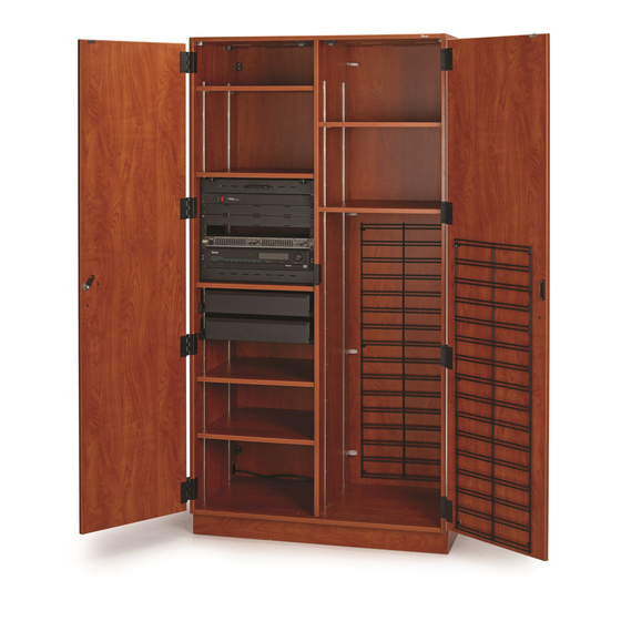
Page 4: Component Identification
Component Identification Structural Components Adjustable Shelf Fixed Shelf Rackmount Organizer Slide-Out Shelf Wire Clamp (#8) 4” (10 cm) Drawer File Cable Pass Drawer Through... -
Page 5: Weight Limits
Component Identification (continued) Accessories Hook (3-pack) Mic Stand Set Storage Basket CD Holder Cable Minder Accessory Accessory Accessory Accessory Accessory 258A004 258A007 258A003 258A005 258A006 Small Plastic Bin Medium Plastic Bin Medium Divided Plastic Bin Accessory Accessory Accessory 204A007.113 204A007.120 204A007.115 Digital Lock Power Strip... -
Page 6: Hardware Parts List
Hardware Parts List 145A288 253A115 Cabinet Connector Bracket Cabinet Cleat X001872 X001503 X000045 X001797 #10-16 x 3/4 #8-15 x 5/8 1/4-14 x 5/8 #8 x 2 Sheet Metal Screw Sheet Metal Screw Sheet Metal Screw Wood Screw X003599 X003632 Shelf Clip Cage Nut X003600 Wire Clamp... -
Page 7: Installation
Installation IMPORTANT: The following procedures are shown using the 2-Column Fixed Media Cabinet, the procedures for the 1-Column Fixed Media Cabinet are similar unless indicated otherwise. Leveling the Cabinet 1. Position the Cabinet at the installation location. 2. The Leveling Glides are located under the Bottom Panel or Panels. - Page 8 #10-16 x 3/4 Sheet Metal Screws (#4) After anchoring to floor. 1/4-14 x 5/8 Sheet Metal Screw Cabinet Cleat (#3) (#2) Anchor to floor using appropriate fasteners. For applications requiring stamped seismic approval, see your Wenger Sales Representative.
- Page 9 #8-15 x 5/8 Sheet Metal Screws (#5) Cabinet Connector Bracket (#1) Anchor to wall using appropriate fasteners. CAUTION The cabinet must be anchored to both the floor and a wall. For applications requiring stamped seismic approval, see your Wenger Sales Representative.
- Page 10 Installation (continued) Attach the Bottom Panels 1. Slide all of the Bottom Panel(s) back into their original position and align any joints along the front edges. 2. Secure the Bottom Panels to the Front Stretcher Panel using one #8 x 2 Wood Screw (#6) in each of the predrilled holes.
- Page 11 Installation (continued) Position the Adjustable Shelves 1. Remove any screws that held the Adjustable Shelves in place during shipping. Remove These screws can be discarded. Screws 2. For each Adjustable Shelf being placed, position one Shelf Clip (#7) at even elevations on each of the four Rails. 3.
-
Page 12: Operation
Operation Repositioning Drawers and Slide-Out Shelves 1. Drawers and Slide-Out Shelves can be repositioned at different heights in 1/2” (1.27 cm) increments by relocating the Glides along the Rails. a. Remove the Drawer or the Slide-Out Shelf and Stop Bracket from the Glides by first pulling it outward, then tilting it up and lifting it out. - Page 13 Operation (continued) Rackmount Electronics 1. Electronic components can be accessed by tipping out the Rackmount. 2. Additional electronic components can be added but must be done so according to their manufacturer’s specifications. Place deeper components at the bottom of the Rackmount. 3.
- Page 14 Operation (continued) Cable Management Cable Pass Throughs are located at the top and sides to route cables through the Cabinet. Notches in the Shelves and Dividers allow cables to be routed at the back of the Cabinet. Wire Clamps assist in routing cables throughout the Cabinet. The Clamps can be repositioned or more can be added as needed.
-
Page 15: Template For Mounting Power Strip
Template for Mounting Power Strip The Power Strip Accessory may be placed at any location in the Cabinet. Secure the Power Strip mounting holes using two #8 x 5/8 Sheet Metal Screws and this template. IMPORTANT: Be sure that this page is printed at 100% actual size before using template. - Page 16 This page is intentionally blank.
Need help?
Do you have a question about the Fixed Media Cabinets and is the answer not in the manual?
Questions and answers