Advertisement
Available languages
Available languages
Quick Links
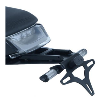
FITTING INSTRUCTIONS FOR LP0250BK LICENCE PLATE BRACKET
(FOR USE WITH STANDARD AND R&G MINI INDICATORS (8mm))
Page | 1
THIS KIT CONTAINS THE ITEMS PICTURED AND LABELLED BELOW.
DO NOT PROCEED UNTIL YOU ARE SURE ALL PARTS ARE PRESENT.
Please note that the way the kit is packed does not necessarily represent the way of
T
HE PARTS SHOWN MAY BE REPRESENTATIVE ONLY
Digital copies of these instructions are available to download from
Please note that in cases where kits are packed with rubber washers holding the components
Unit 1, Shelley's Lane, East Worldham, Alton, Hampshire, GU34 3AQ
Tel: +44 (0)1420 89007 Fax: +44 (0)1420 87301
HUSQVARNA VITPILEN/SVARTPILEN 401 2018
mounting to the bike
GENERAL TORQUE SETTINGS
M4 BOLT = 8Nm
M5 BOLT = 12Nm
M6 BOLT = 15Nm
M8 BOLT = 20Nm
M10 BOLT = 40Nm
onto the bolt – the rubber washers should be thrown away!
TOOLS REQUIRED
•
Set of metric Allen keys.
•
Socket set to include 8, 10, 12 and 13mm A/F socket and wrench.
•
Torx bits to include T20, 25, 30, 40 and 45.
•
Set of metric spanners to include 9, 12 and 13mm A/F sizes.
•
•
Electrical pliers/crimps.
•
Small amount of super glue.
R&G Racing
(
FOR CLARITY OF INSTRUCTIONS ONLY
www.rg-racing.com
Phillips driver.
www.rg-racing.com
Email:
1
LP0250
)
info@rg-racing.com
Advertisement

Related Manuals for R&G LP0250BK


Summary of Contents for R&G LP0250BK
- Page 1 LP0250 FITTING INSTRUCTIONS FOR LP0250BK LICENCE PLATE BRACKET HUSQVARNA VITPILEN/SVARTPILEN 401 2018 (FOR USE WITH STANDARD AND R&G MINI INDICATORS (8mm)) Page | 1 THIS KIT CONTAINS THE ITEMS PICTURED AND LABELLED BELOW. DO NOT PROCEED UNTIL YOU ARE SURE ALL PARTS ARE PRESENT.
- Page 2 LP0250 Page | 2 LEGEND ITEM 1 = LICENCE PLATE BRACKET (TB0250 PART 1) (x1). ITEM 2 = M8 x 35mm LONG BUTTON HEAD BOLTS (x4). ITEM 3 = M8 WASHER (x4). ITEM 4 = RUBBER GROMMETS (RB0006) (x2). ITEM 5 = RGR0003 4W SPECIAL RESISTORS (x2). ITEM 6 = SILICON INDICATOR NUT COVERS (IWC0002) (x2).
- Page 3 LP0250 Page | 3 Picture 1 Picture 2 Picture 3 Picture 4 Picture 5 Picture 6 R&G Racing Unit 1, Shelley’s Lane, East Worldham, Alton, Hampshire, GU34 3AQ Tel: +44 (0)1420 89007 Fax: +44 (0)1420 87301 www.rg-racing.com Email: info@rg-racing.com...
- Page 4 LP0250 Page | 4 Picture 7 Picture 8 Picture 9 Picture 10 Picture 11 Picture 12 R&G Racing Unit 1, Shelley’s Lane, East Worldham, Alton, Hampshire, GU34 3AQ Tel: +44 (0)1420 89007 Fax: +44 (0)1420 87301 www.rg-racing.com Email: info@rg-racing.com...
- Page 5 LP0250 Page | 5 Picture 13 Picture 14 Picture 15 Picture 16 Picture 17 Picture 18 R&G Racing Unit 1, Shelley’s Lane, East Worldham, Alton, Hampshire, GU34 3AQ Tel: +44 (0)1420 89007 Fax: +44 (0)1420 87301 www.rg-racing.com Email: info@rg-racing.com...
- Page 6 LP0250 Page | 6 Picture 19 Picture 20 Picture 21 Picture 22 Picture 23 Picture 24 R&G Racing Unit 1, Shelley’s Lane, East Worldham, Alton, Hampshire, GU34 3AQ Tel: +44 (0)1420 89007 Fax: +44 (0)1420 87301 www.rg-racing.com Email: info@rg-racing.com...
- Page 7 LP0250 Page | 7 Picture 25 Picture 26 Picture 27 Picture 28 Picture 29 Picture 30 R&G Racing Unit 1, Shelley’s Lane, East Worldham, Alton, Hampshire, GU34 3AQ Tel: +44 (0)1420 89007 Fax: +44 (0)1420 87301 www.rg-racing.com Email: info@rg-racing.com...
-
Page 8: Fitting Instructions
LP0250 FITTING INSTRUCTIONS Please note when removing or refitting the original indicators special care must be taken not to damage the circuit board that is located near the plug socket as shown below (this board will be damaged if distorted or if cable ties are used directly onto it —so care should Page | 8 be taken). - Page 9 LP0250 Page | 9 • Feed the indicator wiring through the nut/wire cover (item 6) as shown in pictures 19 and 20 (it helps if a small amount of liquid detergent is used) and position the nut cover over the nut as shown in picture 21 (repeat the above for the opposite indicator). •...
- Page 10 LP0250 ISSUE 2 07/09/2018 (NSY) Page | 10 CONSUMER NOTICE The catalogue description and any exhibition of samples are only broad indications of the Products and R&G may make design changes which do not diminish their performance or visual appeal and supplying them in such state shall conform to the order. The Buyer acknowledges no representation or warranty (other than as to title) has been given or will apply to the Products other than those in R&G’s order or confirmation and the Buyer confirms it has chosen the Products as being of merchantable quality and suitable for its particular purposes.
-
Page 11: Outils Requis
LP0250 NOTICE DE MONTAGE POUR LP0250BK SUPPORT DE PLAQUE HUSQVARNA VITPILEN/SVARTPILEN 401 2018 (POUR MINI CLIGNOTANTS R&G OU CLIGNOTANTS STANDARDS (8mm)) Page | 11 Le kit contient les articles exposés ci-dessous, vérifier que toutes les pièces soient présentes avant de procéder au montage. - Page 12 LP0250 Page | 12 LÉGENDE ARTICLE 1 = SUPPORT DE PLAQUE (TB0250 PART 1) (x1). ARTICLE 2 = M8 x 35mm BOULONS (x4). ARTICLE 3 = M8 RONDELLES (x4). ARTICLE 4 = RONDELLES EN CAOUTCHOUC (RB0006) (x2). ARTICLE 5 = RGR0003 4W RÉSISTANCES SPÉCIALES (x2). ARTICLE 6 = CACHES ÉCROU EN SILICONE POUR CLIGNOTANT (IWC0002) (x2).
-
Page 13: Notice De Montage
LP0250 ARTICLE 15 = COLLIERS DE SERRAGE (x4). ARTICLE 16 = CONNECTEUR DE FEU DE PLAQUE (CON0026) (x1). ARTICLE 17 = CONNECTEURS DE MINI CLIGNOTANT (CON0014) (x2). Page | 13 NOTICE DE MONTAGE Notez que lors du démontage ou du remontage des clignotants d’origine, vous devez être particulièrement attentif pour ne pas endommager le circuit imprimé... - Page 14 LP0250 • Monter les clignotants dans le nouveau support de plaque (article 1) puis fixer comme à l’origine (veiller à ce qu’ils soient montés du bon côté). Si vous utilisez des mini clignotants • Pour monter les mini clignotants R&G (R&G code produit RG371 pour type LED ou Page | 14 RG372 pour type LED latérale).
- Page 15 LP0250 • Remonter le siège comme à l’origine ainsi que la plaque d’immatriculation (cette opération peut nécessiter un perçage). • Vérifier que tous les feux fonctionnent avant de prendre la route. • IMPORTANT : Si vous installez une grosse plaque, qui plus de façon assez basse sur le support de plaque, il y a un risque que la plaque entre en contact avec la Page | 15 roue arrière en cas de choc sur la route (bosse, grosse charge etc..).
-
Page 16: Sie Benötigen Folgendes Werkzeug
LP0250 MONTAGEANLEITUNG FÜR LP0250BK KENNZEICHENHALTER HUSQVARNA VITPILEN/SVARTPILEN 401 2018 - VERWENDUNG MIT STANDARDBLINKER UND R&G MINIBLINKER (8mm) Page | 16 ALLE KIT-TEILE SIND UNTEN ABGEBILDET UND GEKENNZEICHNET. BEVOR SIE MIT DER MONTAGE BEGINNEN, ÜBERPRÜFEN SIE, DASS ALLE TEILE VORHANDEN SIND. - Page 17 LP0250 Page | 17 LIEFERUMFANG ARTIKEL 1 = KENNZEICHENHALTER (TB0250 TEIL 1) (x1) ARTIKEL 2 = M8 x 35mm INBUSSCHRAUBEN (x4) ARTIKEL 3 = M8 UNTERLEGSCHEIBEN (x4) ARTIKEL 4 = GUMMITÜLLEN (RB0006) (x2) ARTIKEL 5 = RGR0003 4W SPEZIELLE WIDERSTÄNDE (x2) ARTIKEL 6 = ABDECKUNGEN FÜR DIE MUTTER (BLINKER) AUS SILIKON (IWC0002) (x2) ARTIKEL 7 = KLEINE GUMMITÜLLEN (RB50-20-00FG) (x2) ARTIKEL 8 = 200mm SCHRUMPFSCHLAUCH (x3)
- Page 18 LP0250 ARTIKEL 16 = VERBINDUNG FÜR DIE KENNZEICHENBELEUCHTUNG (CON0026) (x1) ARTIKEL 17 = VERBINDUNGEN FÜR DIE MINIBLINKER (CON0014) (x2) Page | 18 MONTAGEANLEITUNG Bitte beachten Sie bei der Entfernung bzw. Neumontierung der original Blinker, dass die Platine, die in der Nähe des Steckverbinders positioniert ist (siehe unten), nicht beschädigt wird.
- Page 19 LP0250 Wenn Sie die original Blinker verwenden • Montieren Sie die Blinker am neuen Kennzeichenhalter (Artikel 1) und wie ursprünglich befestigen (bitte darauf achten, dass sie an der richtigen Seite montiert sind). Page | 19 Wenn Sie R&G Miniblinker verwenden: •...
- Page 20 LP0250 • Den Kettenschutz (ohne Kabel) wie ursprünglich zusammenbauen (siehe Abbildung 11) und wieder am Motorrad mit den Originalschrauben montieren. Die hinterste Schraube benötigt den 5mm Distanzhalter (Artikel 11) – siehe Abbildung 28. • Wenn Sie R&G LED-Miniblinker verwenden, benötigen Sie je einen Widerstand (Artikel 5) an jedem Blinker, um die richtige Blitzgeschwindigkeit zu bekommen (siehe Abbildung 29).
Need help?
Do you have a question about the LP0250BK and is the answer not in the manual?
Questions and answers