Table of Contents
Advertisement
Available languages
Available languages
Quick Links
Page 1 of 22
LP0294
FITTING INSTRUCTIONS FOR LP0294BK LICENCE PLATE BRACKET
YAMAHA T-MAX 560 2020-
This kit contains the items pictured and labelled over page.
Some parts may be shown for clarity of instructions only.
Do not proceed until you are sure all parts are present.
Please read all instructions before proceeding.
IF IN ANY DOUBT WHEN FITTING OUR PRODUCTS, CONSULT ONE OF OUR DEALERS
OR HAVE FITTED BY A QUALIFIED TECHNICIAN.
Please note that the way the kit is packed does not necessarily represent the way of
mounting to the bike.
In the event of rubber washers being used to hold components onto bolts,
these rubber washers can be thrown away.
DIGITAL COPIES OF THESE INSTRUCTIONS ARE AVAILABLE FROM
WWW.RG-RACING.COM
R&G
Unit
, Shelley's Lane, East Worldham, Alton, Hampshire, GU34 3AQ
1
Tel: +44 (0)
420 89007 Fax: +44 (0)
420 87301 www.rg-racing.com Email: info@rg-racing.com
1
1
Advertisement
Table of Contents

Related Manuals for R&G LP0294BK


Summary of Contents for R&G LP0294BK
- Page 1 Page 1 of 22 LP0294 FITTING INSTRUCTIONS FOR LP0294BK LICENCE PLATE BRACKET YAMAHA T-MAX 560 2020- This kit contains the items pictured and labelled over page. Some parts may be shown for clarity of instructions only. Do not proceed until you are sure all parts are present.
-
Page 2: Tools Required
Page 2 of 22 LP0294 TOOLS REQUIRED GENERAL TORQUE SETTINGS • Set of metric Allen keys. M4 BOLT = 8Nm • Set of metric sockets and wrench. M5 BOLT = • 12mm spanner. • Phillips screwdriver. M6 BOLT = • Cable cutters M8 BOLT = 20Nm 0 BOLT = 40Nm... -
Page 3: Assembly Diagram
Page 3 of 22 LP0294 ASSEMBLY DIAGRAM R&G Unit , Shelley’s Lane, East Worldham, Alton, Hampshire, GU34 3AQ Tel: +44 (0) 420 89007 Fax: +44 (0) 420 87301 www.rg-racing.com Email: info@rg-racing.com... - Page 4 Page 4 of 22 LP0294 Picture 1 Picture 2 Picture 3 Picture 4 Picture 5 Picture 6 R&G Unit , Shelley’s Lane, East Worldham, Alton, Hampshire, GU34 3AQ Tel: +44 (0) 420 89007 Fax: +44 (0) 420 87301 www.rg-racing.com Email: info@rg-racing.com...
- Page 5 Page 5 of 22 LP0294 Picture 7 Picture 8 Picture 9 Picture 10 R&G Unit , Shelley’s Lane, East Worldham, Alton, Hampshire, GU34 3AQ Tel: +44 (0) 420 89007 Fax: +44 (0) 420 87301 www.rg-racing.com Email: info@rg-racing.com...
- Page 6 Page 6 of 22 LP0294 Picture 11 Picture 12 Picture 13 Picture 14 Picture 15 Picture 16 R&G Unit , Shelley’s Lane, East Worldham, Alton, Hampshire, GU34 3AQ Tel: +44 (0) 420 89007 Fax: +44 (0) 420 87301 www.rg-racing.com Email: info@rg-racing.com...
- Page 7 Page 7 of 22 LP0294 Picture 17 Picture 18 Picture 19 Picture 20 Picture 21 R&G Unit , Shelley’s Lane, East Worldham, Alton, Hampshire, GU34 3AQ Tel: +44 (0) 420 89007 Fax: +44 (0) 420 87301 www.rg-racing.com Email: info@rg-racing.com...
-
Page 8: Fitting Instructions
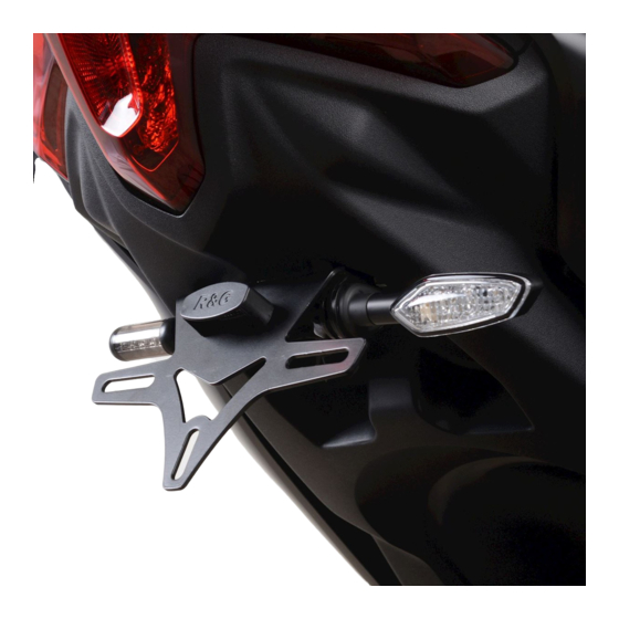
Page 8 of 22 LP0294 FITTING INSTRUCTIONS FITTING INSTRUCTIONS • To fit the R&G tail tidy, lift the seat using the key and release button. • Remove the two plastic covers on the handrail on the left side of the bike, as arrowed in picture 1, and remove the two bolts underneath. - Page 9 Page 9 of 22 LP0294 • Feed the indicator wiring through the hole on the licence plate bracket, positioning the raised boss on the adaptor within the hole, before positioning a second mini indicator adaptor (item 5 – I0016) (with the boss facing toward the indicator) over the wiring and into the hole on the bracket, before fitting the indicator nut over the wiring and tighten onto the threaded stalk of the indicator, as shown in picture 19.
- Page 10 Page 10 of 22 LP0294 To continue • Feed the wires of the new R&G licence plate illuminator (item 2) through the central hole in the new licence plate bracket (item 1). • Secure using the washers and nuts supplied as shown in picture 19. •...
- Page 11 Page 11 of 22 LP0294 NOTICE DE MONTAGE POUR LP0294BK SUPPORT DE PLAQUE YAMAHA T-MAX 560 2020- E KIT CONTIENT LES ARTICLES ILLUSTRES ET ETIQUETES SUR LA PAGE ERTAINES PARTIES PEUVENT ETRE PRESENTES UNIQUEMENT POUR LA CLARTE DES INSTRUCTIONS E PAS PROCEDER AU MONTAGE TANT QUE VOUS N...
-
Page 12: Outils Requis
Page 12 of 22 LP0294 OUTILS REQUIS VALEURS DE SERRAGE • Clés Allen M4 BOULON = 8Nm • Clé à cliquet + douilles M5 BOULON = • Clé à molette 12mm. • Tournevis cruciforme. M6 BOULON = • Pince coupante M8 BOULON = 20Nm 0 BOULON = 40Nm M12 BOULON = 40Nm... -
Page 13: Schéma D'ensemble
Page 13 of 22 LP0294 SCHÉMA D’ENSEMBLE R&G Unit , Shelley’s Lane, East Worldham, Alton, Hampshire, GU34 3AQ Tel: +44 (0) 420 89007 Fax: +44 (0) 420 87301 www.rg-racing.com Email: info@rg-racing.com... -
Page 14: Notice De Montage
Page 14 of 22 LP0294 NOTICE DE MONTAGE NOTICE DE MONTAGE • Pour installer le support arrière R&G, soulevez le siège à l'aide de la clé et du bouton de déverrouillage. • Retirez les deux couvercles en plastique de la main courante du côté gauche de la moto, comme indiqué... - Page 15 Page 15 of 22 LP0294 Retirez la pièce en plastique du support en caoutchouc de clignotant. Comme indiqué sur la photo 14. Une fois celle-ci retirée, retirez la vis de fixation de clignotant comme indiqué sur la photo 15. Tirez sur le support en caoutchouc du trou en plastique et sur l’onglet en plastique et faites sortir le clignotant et le câblage du support de plaque d'immatriculation d’origine, comme indiqué...
- Page 16 Page 16 of 22 LP0294 Suite: • Faites passer les fils du nouvel éclairage de plaque d'immatriculation R&G (article 2) à travers le trou central du nouveau support de plaque d'immatriculation (article 1). • Fixez à l'aide des rondelles et des écrous fournis comme indiqué sur la photo 19. •...
- Page 17 Page 17 of 22 LP0294 MONTAGEANLEITUNG FÜR LP0294BK KENNZEICHENHALTER YAMAHA T-MAX 560 2020- Alle Kit-Teile sind auf den folgenden Seiten abgebildet und gekennzeichnet Die abgebildeten Teile dienen lediglich zur Erklärung. Überprüfen Sie zuerst, dass alle Teile vorhanden sind. Lesen Sie die Montageanleitung komplett durch, bevor Sie anfangen.
- Page 18 Page 18 of 22 LP0294 SIE BENÖTIGEN FOLGENDE WERKZEUGE: ALLGEM. ANZUGSDREHMOMENT: • Satz Inbusschlüssel M4 SCHRAUBE = 8Nm • Satz Steckschlüssel M5 SCHRAUBE = • 12mm Schraubenschlüssel • Kreuzschlitzschraubendreher M6 SCHRAUBE = • Seitenschneider M8 SCHRAUBE = 20Nm 0 SCHRAUBE = 40Nm M12 SCHRAUBE = 40Nm LIEFERUMFANG ARTIKEL-NR.
- Page 19 Page 19 of 22 LP0294 ZUSAMMENBAU ZEICHNUNG R&G Unit 1, Shelley’s Lane, East Worldham, Alton, Hampshire, GU34 3AQ Tel: +44 (0)1420 89007 Fax: +44 (0)1420 87301 www.rg-racing.com Email: info@rg-racing.com...
- Page 20 Page 20 of 22 LP0294 MONTAGEANLEITUNG • Um den R&G Kennzeichenhalter montieren zu können, zuerst den Sitz hochklappen mit Hilfe des Schlüssels und Auslöseknopfs. • Entfernen Sie die zwei Kunststoffabdeckungen am Haltegriff an der linken Seite des Motorrads wie in Abbildung 1 gekennzeichnet, und entfernen Sie die zwei Schrauben an der Unterseite. Entfernen Sie den Haltegriff vom Motorrad.
- Page 21 Page 21 of 22 LP0294 • Führen Sie die Kabel eines Blinkers durch die Öffnung eines Miniblinker-Adapters (Artikel 5 – I0016) – achten Sie darauf, dass die erhöhte Nabe des Adapters weg vom Blinker gerichtet ist. • Führen Sie die Verkabelung der Blinker durch die Öffnung im Kennzeichenhalter, die erhöhte Nabe des Adapter innerhalb der Öffnung positionieren, bevor Sie einen zweiten Miniblinker- Adapter (Artikel 5 –...
- Page 22 Page 22 of 22 LP0294 • Montieren Sie Seitenverkleidungen sowie Haltegriffe wieder in umgekehrter Reihenfolge des vorherigen Abbaus. • Montieren Sie das amtliche Kennzeichen wieder (Bohrungen im Kennzeichen evtl. notwendig). • Entsprechend der gesetzlichen Vorschriften, den mitgelieferten Rückstrahler (Artikel 12) an die dafür vorgesehene Stelle anbringen.
Need help?
Do you have a question about the LP0294BK and is the answer not in the manual?
Questions and answers