Advertisement
Available languages
Available languages
Quick Links
LP0274
PAGE 1 OF 24
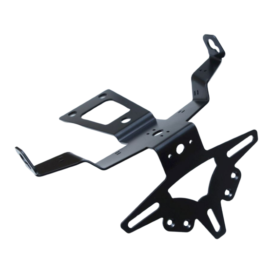
FITTING INSTRUCTIONS FOR LP0274BK LICENCE PLATE BRACKET
DUCATI HYPERMOTARD 950 2019- (SINGLE SIDED EXHAUST) -
Picture A
Picture B
T
.
HIS KIT CONTAINS THE ITEMS PICTURED AND LABELLED OVER PAGE
S
.
OME PARTS MAY BE SHOWN FOR CLARITY OF INSTRUCTIONS ONLY
D
.
O NOT PROCEED UNTIL YOU ARE SURE ALL PARTS ARE PRESENT
P
.
LEASE READ ALL INSTRUCTIONS BEFORE PROCEEDING
IF IN ANY DOUBT WHEN FITTING OUR PRODUCTS, CONSULT ONE OF OUR DEALERS
OR HAVE FITTED BY A QUALIFIED TECHNICIAN.
P
LEASE NOTE THAT THE WAY THE KIT IS PACKED DOES NOT NECESSARILY REPRESENT THE WAY OF
.
MOUNTING TO THE BIKE
I
,
N THE EVENT OF RUBBER WASHERS BEING USED TO HOLD COMPONENTS ONTO BOLTS
.
THESE RUBBER WASHERS CAN BE THROWN AWAY
DIGITAL COPIES OF THESE INSTRUCTIONS ARE AVAILABLE FROM:
WWW.RG-RACING.COM
R&G Racing
Unit 1, Shelly's Lane, East Worldham, Alton, Hampshire GU34 3AQ.
Tel: +44 (0)1420 89007 Fax +44 (0)1420 87301
www.rg-racing.com
Email:
info@rg-racing.com
Advertisement

Subscribe to Our Youtube Channel
Related Manuals for R&G LP0274BK


Summary of Contents for R&G LP0274BK
- Page 1 LP0274 PAGE 1 OF 24 FITTING INSTRUCTIONS FOR LP0274BK LICENCE PLATE BRACKET DUCATI HYPERMOTARD 950 2019- (SINGLE SIDED EXHAUST) - Picture A Picture B HIS KIT CONTAINS THE ITEMS PICTURED AND LABELLED OVER PAGE OME PARTS MAY BE SHOWN FOR CLARITY OF INSTRUCTIONS ONLY...
- Page 2 PAGE 2 OF 24 LP0274 TOOLS REQUIRED GENERAL TORQUE SETTINGS • Set of metric Allen keys to include 4 & M4 BOLT = 8Nm M5 BOLT = • Socket set to include 6mm & 8mm M6 BOLT = • T20 Torx tool •...
-
Page 3: Assembly Diagram
LP0274 PAGE 3 OF 24 ASSEMBLY DIAGRAM 1 ASSEMBLY DIAGRAM 2 R&G Racing Unit 1, Shelly’s Lane, East Worldham, Alton, Hampshire GU34 3AQ. Tel: +44 (0)1420 89007 Fax +44 (0)1420 87301 www.rg-racing.com Email: info@rg-racing.com... - Page 4 PAGE 4 OF 24 LP0274 Picture 2 Picture 1 R&G Racing Unit 1, Shelly’s Lane, East Worldham, Alton, Hampshire GU34 3AQ. Tel: +44 (0)1420 89007 Fax +44 (0)1420 87301 www.rg-racing.com Email: info@rg-racing.com...
- Page 5 LP0274 PAGE 5 OF 24 Picture 4 Picture 3 Picture 5 Picture 6 Picture 7 Picture 8 R&G Racing Unit 1, Shelly’s Lane, East Worldham, Alton, Hampshire GU34 3AQ. Tel: +44 (0)1420 89007 Fax +44 (0)1420 87301 www.rg-racing.com Email: info@rg-racing.com...
- Page 6 PAGE 6 OF 24 LP0274 Picture 9 Picture 10 Picture 11 Picture 12 Picture 13 Picture 14 R&G Racing Unit 1, Shelly’s Lane, East Worldham, Alton, Hampshire GU34 3AQ. Tel: +44 (0)1420 89007 Fax +44 (0)1420 87301 www.rg-racing.com Email: info@rg-racing.com...
- Page 7 LP0274 PAGE 7 OF 24 Picture 15 Picture 16 Picture 17 R&G Racing Unit 1, Shelly’s Lane, East Worldham, Alton, Hampshire GU34 3AQ. Tel: +44 (0)1420 89007 Fax +44 (0)1420 87301 www.rg-racing.com Email: info@rg-racing.com...
-
Page 8: Fitting Instructions
PAGE 8 OF 24 LP0274 FITTING INSTRUCTIONS OEM Tail Unit Removal: • Begin by removing the panel under the tail unit by removing the two bolts arrowed in picture 1 using a 4mm allen key. • Carefully remove the 3 allen head bolts holding the OEM licence plate holder to the bike shown in picture 2 using a 6mm allen key, ensuring to support the unit when removing these bolts to prevent the unit dropping. - Page 9 LP0274 PAGE 9 OF 24 • Using a 4mm allen key, remove the rubber indicator stem of each indicator by removing the cap head bolt as in picture 8 and remove the rubber stem from the indicator. • Feed the wire of the indicator through the indicator mount on the tail tidy bracket. To secure this, cut a small slot into one mini indicator adapter (item 3) per side, and thread the wire through this as shown in pictures 9 &...
- Page 10 PAGE 10 OF 24 LP0274 • With all lights working, offer the complete tail tidy assembly up to the rear of the bike and use the 3 x OEM cap head bolts removed earlier and loosely fix this in place as shown in Picture 16. •...
- Page 11 LP0274 PAGE 11 OF 24 NOTICE DE MONTAGE LP0274BK SUPPORT DE PLAQUE DUCATI HYPERMOTARD 950 2019- (ECHAPPEMENT D’UN SEUL COTE) - Photo A Photo B E KIT CONTIENT LES ARTICLES EN PHOTO ET ETIQUETTES SUR LA PAGE LES PARTIES PRESENTÉES PEUVENT ETRE UNIQUEMENT REPRESENTATIVES POUR LA CLARTE DES INSTRUCTIONS E PAS ROCÉDER AU MONTAGE AVANT DE VOUS ÊTRES ASSURE QUE TOUTES LES PIECES SOIENT PRÉSENTES...
-
Page 12: Outils Requis
PAGE 12 OF 24 LP0274 OUTILS REQUIS VALEURS DE SERRAGE • Clés Allen 4 & 6mm M4 BOULON = 8Nm • Clé à cliquet + douilles 6mm & 8mm M5 BOULON = • Clé Torx T20 M6 BOULON = • Clé... - Page 13 LP0274 PAGE 13 OF 24 SCHEMA DE MONTAGE 1 SCHEMA DE MONTAGE 2 R&G Racing Unit 1, Shelly’s Lane, East Worldham, Alton, Hampshire GU34 3AQ. Tel: +44 (0)1420 89007 Fax +44 (0)1420 87301 www.rg-racing.com Email: info@rg-racing.com...
- Page 14 PAGE 14 OF 24 LP0274 R&G Racing Unit 1, Shelly’s Lane, East Worldham, Alton, Hampshire GU34 3AQ. Tel: +44 (0)1420 89007 Fax +44 (0)1420 87301 www.rg-racing.com Email: info@rg-racing.com...
-
Page 15: Notice De Montage
LP0274 PAGE 15 OF 24 NOTICE DE MONTAGE Démontage de support de plaque d’origine : • Commencez par retirer le panneau situé sous l’arrière en retirant les deux boulons fléchés sur la photo 1 à l’aide d’une clé Allen de 4 mm. •... - Page 16 PAGE 16 OF 24 LP0274 • À l’aide d’une clé Allen de 4 mm, retirez la tige en caoutchouc de chaque clignotant en retirant le boulon à comme sur la photo 8, puis retirez la tige en caoutchouc du clignotant •...
- Page 17 LP0274 PAGE 17 OF 24 Montage du support de plaque : • Une fois les deux clignotants et le feu de plaque attachés au support, vous devez maintenant con- necter le faisceau de câbles de l'unité d’origine enlevée précédemment, aux connecteurs de cligno- tant et du feu de plaque, en veillant à...
- Page 18 PAGE 18 OF 24 LP0274 MONTAGEANLEITUNG FÜR LP0274BK KENNZEICHENHALTER DUCATI HYPERMOTARD 950 2019- (EINSEITIGER AUSPUFF) Abbildung A Abbildung B ALLE KIT-TEILE SIND UNTEN ABGEBILDET UND GEKENNZEICHNET. DIE ABGEBILDETEN TEILE DIENEN LEDIGLICH ZUR ERKLÄRUNG. ÜBERPRÜFEN SIE ZUERST, DASS ALLE TEILE VORHANDEN SIND.
- Page 19 LP0274 PAGE 19 OF 24 SIE BRAUCHEN FOLGENDES WERKZEUG ALLEM. ANZUGSDREHMOMENT • Satz Inbusschlüssel inkl. 4 & 6mm M4 SCHRAUBE = 8Nm • Stechschlüsselsatz inkl. 6mm & 8mm M5 SCHRAUBE = • T20 Torx-Schlüssel M6 SCHRAUBE = • 12mm A/F Schraubenschlüssel •...
- Page 20 PAGE 20 OF 24 LP0274 ZUSAMMENBAU ZEICHNUNG 1 ZUSAMMENBAU ZEICHNUNG 2 R&G Racing Unit 1, Shelly’s Lane, East Worldham, Alton, Hampshire GU34 3AQ. Tel: +44 (0)1420 89007 Fax +44 (0)1420 87301 www.rg-racing.com Email: info@rg-racing.com...
- Page 21 LP0274 PAGE 21 OF 24 R&G Racing Unit 1, Shelly’s Lane, East Worldham, Alton, Hampshire GU34 3AQ. Tel: +44 (0)1420 89007 Fax +44 (0)1420 87301 www.rg-racing.com Email: info@rg-racing.com...
- Page 22 PAGE 22 OF 24 LP0274 MONTAGEANLEITUNG Original Kennzeichenhalter—Entfernung: • Beginnen Sie mit der Entfernung des Verkleidungsteils unter dem Heck - die zwei Schrauben, die in Abbildung 1 markiert sind mit einem 4mm Inbusschlüssel lösen und entfernen. • Mit einem 6mm Inbusschlüssel die 3 Inbusschrauben entfernen, die den Kennzeichenhalter am Motorrad befestigen –...
- Page 23 LP0274 PAGE 23 OF 24 • Diese Einheit am Kennzeichenhalter mit den M4 Unterlegscheiben und Muttern vom Kit anbringen wie in Zusammenbau Zeichnung 2 auf Seite 3 abgebildet. Ziehen Sie die Muttern mit einem 6mm Schraubenschlüssel fest. • Die CON14 Verbindung für die Rückbeleuchtung (Artikel 12) mit den Kabelverbindungen der Kennzeichenbeleuchtung verbinden.
- Page 24 PAGE 24 OF 24 LP0274 Kennzeichenhalter montieren: • Nachdem beide Blinker und die Kennzeichenbeleuchtung am Kennzeichenhalter montiert sind, können Sie den zuvor entfernen Kabelstrang vom original Kennzeichenhalter mit den Verbindungen für die Blinker und die Kennzeichenbeleuchtung verbinden. Bitte darauf achten, dass die Blinkerkabel mit der entsprechenden Seite verbunden sind.
Need help?
Do you have a question about the LP0274BK and is the answer not in the manual?
Questions and answers