Table of Contents
Advertisement
Quick Links
LP0253
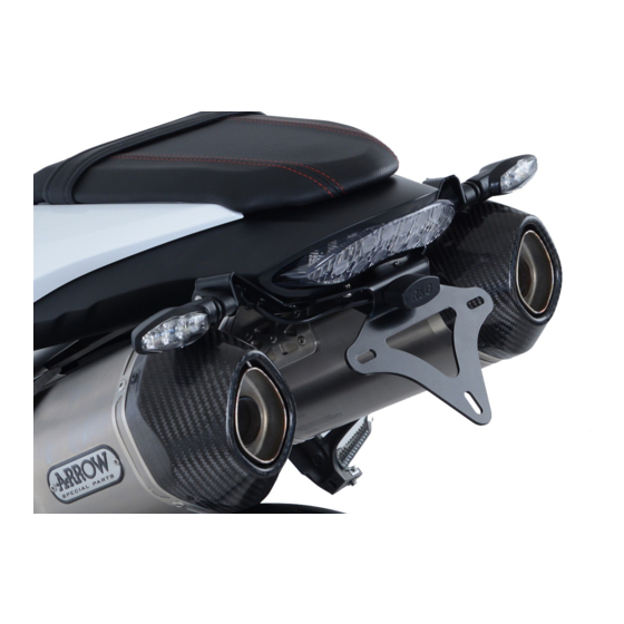
FITTING INSTRUCTIONS FOR LP0253BK LICENCE PLATE BRACKET
TRIUMPH SPEED TRIPLE 1050RS '18-
Page | 1
THIS KIT CONTAINS THE ITEMS PICTURED AND LABELLED BELOW.
DO NOT PROCEED UNTIL YOU ARE SURE ALL PARTS ARE PRESENT.
Please note that the way the kit is packed does not necessarily represent the way of mounting to the bike.
T
(
).
HE PARTS SHOWN MAY BE REPRESENTATIVE ONLY
FOR CLARITY OF INSTRUCTIONS ONLY
R&G
Unit 1, Shelley's Lane, East Worldham, Alton, Hampshire, GU34 3AQ
Tel: +44 (0)1420 89007 Fax: +44 (0)1420 87301
www.rg-racing.com
Email:
info@rg-racing.com
Advertisement
Table of Contents

Related Manuals for R&G LP0253BK


Summary of Contents for R&G LP0253BK
- Page 1 LP0253 FITTING INSTRUCTIONS FOR LP0253BK LICENCE PLATE BRACKET TRIUMPH SPEED TRIPLE 1050RS ’18- Page | 1 THIS KIT CONTAINS THE ITEMS PICTURED AND LABELLED BELOW. DO NOT PROCEED UNTIL YOU ARE SURE ALL PARTS ARE PRESENT. Please note that the way the kit is packed does not necessarily represent the way of mounting to the bike.
-
Page 2: Tools Required
LP0253 Page | 2 LEGEND ITEM 1 = LICENCE PLATE BRACKET (TB0194 PART 1). (x1) ITEM 2 = RIGHT SIDE INDICATOR BRACKET (TB0253 PART 2). (x1) ITEM 3 = LEFT SIDE INDICATOR BRACKET (TB0253 PART 3). (x1) ITEM 4 = COVER PLATE (TB0194 PART 4). (x1) ITEM 5 = WIRING COVER (TB0253 PART 1). - Page 3 LP0253 Page | 3 Picture 1 Picture 2 Picture 3 Picture 4 Picture 5 Picture 6 R&G Unit 1, Shelley’s Lane, East Worldham, Alton, Hampshire, GU34 3AQ Tel: +44 (0)1420 89007 Fax: +44 (0)1420 87301 www.rg-racing.com Email: info@rg-racing.com...
- Page 4 LP0253 Page | 4 Picture 7 Picture 8 Picture 9 Picture 10 Picture 11 Picture 12 R&G Unit 1, Shelley’s Lane, East Worldham, Alton, Hampshire, GU34 3AQ Tel: +44 (0)1420 89007 Fax: +44 (0)1420 87301 www.rg-racing.com Email: info@rg-racing.com...
-
Page 5: Fitting Instructions
LP0253 Page | 5 Picture 13 Picture 14 Picture 15 Picture 16 FITTING INSTRUCTIONS • Remove pillion seat using the key. • Remove the two button head bolts that hold the main seat. • Remove the 3 bolts from both rear panels shown in picture 3. •... - Page 6 LP0253 Indicators can be mounted from the indicator brackets (item 2 & 3) or from the wiring cover (item 5) depending on the desired look. If using OEM indicators • Remove the bolt from each indicator. Page | 6 • Remove the 2 bolts and 2 clips arrowed in picture 7.
- Page 7 LP0253 • Gently slide the OEM rear panel back in and locate the cover plate on the inside. Push the OEM push pins back in their original position, securing the cover plate. • If using OEM indicators connect these to the OEM sub loom removed earlier. •...
- Page 8 LP0253 NOTICE DE MONTAGE POUR LP0253BK SUPPORT DE PLAQUE TRIUMPH SPEED TRIPLE 1050RS ’18- Page | 8 Le kit contient les articles exposés ci-dessous, vérifier que toutes les pièces soient présentes avant de procéder au montage. La façon dont le kit est emballé ne correspond pas forcément à la façon de monter les pièces sur la moto.
-
Page 9: Outils Requis
LP0253 Page | 9 LÉGENDE ARTICLE 1 = SUPPORT DE PLAQUE (TB0194 PARTIE 1). (x1) ARTICLE 2 = SUPPORT CLIGNOTANT CÔTÉ DROIT (TB0253 PART 2). (x1) ARTICLE 3 = SUPPORT CLIGNOTANT CÔTÉ GAUCHE (TB0253 PARTIE 3). (x1) ARTICLE 4 = COUVERCLE (TB0194 PARTIE 4). (x1) ARTICLE 5 = CACHE FIL (TB0253 PARTIE 1). -
Page 10: Notice De Montage
LP0253 NOTICE DE MONTAGE • Enlever le siège à l’aide de la clé. • Enlever les 2 boulons qui fixent le siège principal. Page | 10 • Enlever les 3 boulons des 2 panneaux arrière, voir photo 3. • Enlever les 3 boulons indiqués sur la photo 4 et les 2 onglets places sous le passage de roue, voir la photo 5. Enlever le panneau arrière en le glissant vers le bas. - Page 11 LP0253 • Monter le cache fil sur le support de plaque, voir la photo 13, fixer le cache fil avec 2 petits boulons M6 (article 6) d’un côté. Si vous utilisez le cache fil pour monter les mini clignotants. • Passer le fil de clignotant des 2 clignotants dans les trous du côté...
- Page 12 LP0253 CONSUMER NOTICE The catalogue description and any exhibition of samples are only broad indications of the Products and R&G may make design changes which do not diminish their performance or visual appeal and supplying them in such state shall conform to the order. The Buyer acknowledges no representation or warranty (other than as to title) has been given or will apply to the Products other than those in R&G’s order or confirmation and the Buyer confirms it has chosen the Products as being of merchantable quality and suitable for its particular purposes.
- Page 13 LP0253 MONTAGEANLEITUNG FÜR LP0253BK KENNZEICHENHALTER TRIUMPH SPEED TRIPLE 1050RS ’18- Page | 13 ALLE TEILE SIND UNTEN ABGEBILDET UND GEKENNZEICHNET. BEVOR SIE MIT DER MONTAGE BEGINNEN, ÜBERPRÜFEN SIE, DASS ALLE TEILE VORHANDEN SIND. Hinweis: Die Verpackung der Teile stellt nicht die Reihenfolge der Montage dar.
-
Page 14: Sie Benötigen Folgendes Werkzeug
LP0253 Page | 14 LIEFERUMFANG ARTIKEL 1 = KENNZEICHENHALTER (TB0194 TEIL 1) (x1) ARTIKEL 2 = HALTERUNG FÜR BLINKER RECHTS (TB0253 TEIL 2) (x1) ARTIKEL 3 = HALTERUNG FÜR BLINKER LINKS (TB0253 TEIL 3) (x1) ARTIKEL 4 = ABDECKPLATTE (TB0194 TEIL 4) (x1) ARTIKEL 5 = KABELABDECKUNG (TB0253 TEIL 1) (x1) ARTIKEL 6 = M6 x 6mm INBUSSCHRAUBE (x6) ARTIKEL 7 = M6 x 10mm INBUSSCHRAUBE (x3) - Page 15 LP0253 MONTAGEANLEITUNG • Entfernen Sie den Beifahrersitz (der Schlüssel wird hierfür benötigt). • Entfernen Sie die zwei Inbusschrauben, die den Sitz befestigen. Page | 15 • Entfernen Sie die 3 Schrauben von beiden Heckverkleidungen – siehe Abbildung 3. • Entfernen Sie die 3 Schrauben, die in Abbildung 4 gekennzeichnet sind und die 2 Reißzwecken unten an der unteren Abdeckung –...
- Page 16 LP0253 • Montieren Sie die Halterungen für die Blinker am Kennzeichenhalter (Artikel 1) mit den 2 kleinen M6 Schrauben (Artikel 6) – siehe Abbildung 11. • Die Kabelabdeckung am Kennzeichenhalter anbringen wie in Abbildung 13 abgebildet und die Kabelabdeckung mit den 2 kleinen M6 Schrauben (Artikel 6) an beiden Seiten befestigen. Wenn Sie die Miniblinker an der Kabelabdeckung montieren Page | 16 •...
- Page 17 LP0253 AUSGABE 1 21/08/2018 (HB) Eine digitale Version dieser Montageanleitung kann auf folgender Seite heruntergeladen werden: www.rg-racing.com Page | 17 CONSUMER NOTICE The catalogue description and any exhibition of samples are only broad indications of the Products and R&G may make design changes which do not diminish their performance or visual appeal and supplying them in such state shall conform to the order.
Need help?
Do you have a question about the LP0253BK and is the answer not in the manual?
Questions and answers