Table of Contents
Advertisement
Quick Links
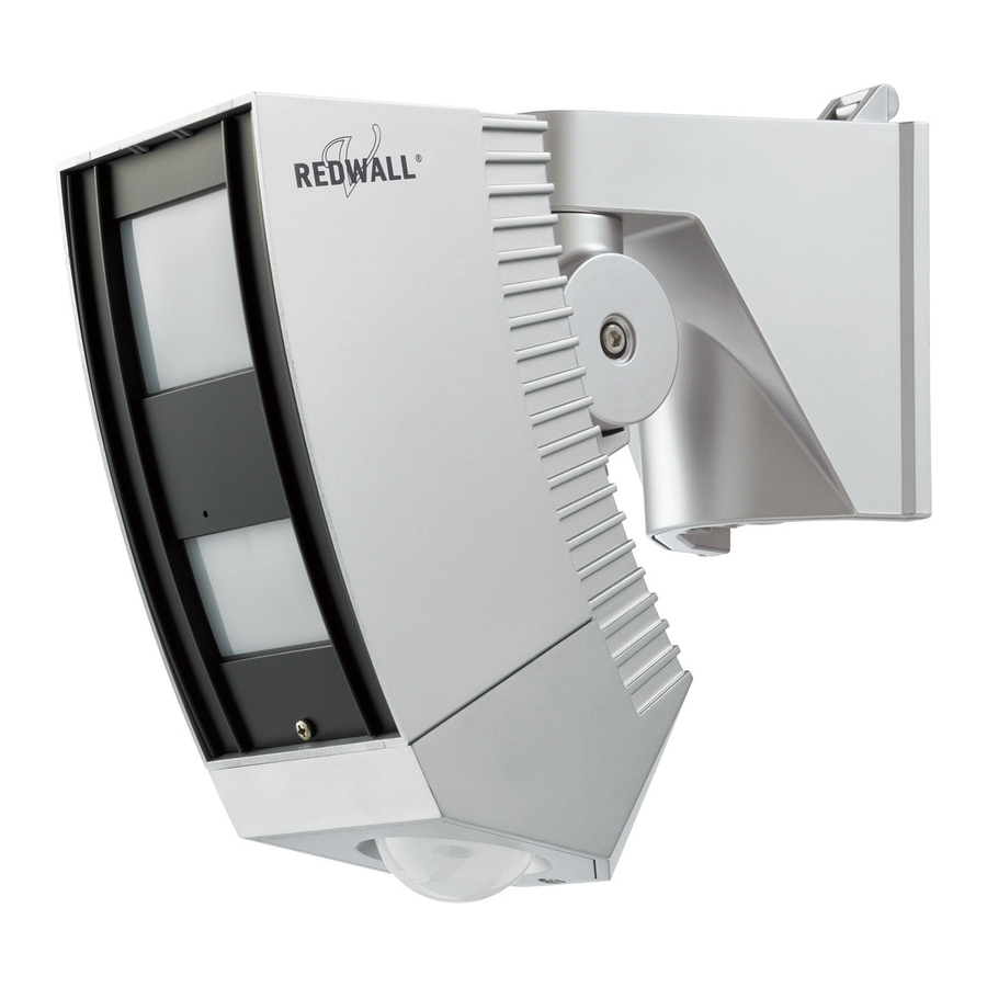
REDWALL-V adjustment procedures guide
This document is provided as a reference tool for installing the
Optex Redwall SIP passive infrared detector. Before starting,
read the instruction book that comes with the unit.
Before starting any installation, please confirm if
proper power is provided to the SIP unit.
Requirements
SIP detector main unit
*Optional (but necessary)
adjustment tools
AVF-1
Area View
Finder
*Included in the kit
Area plate
Allen Key
AWT-3
Area Walk
Tester
Area masking seal
*Other useful tools
Cross slot
Screwdriver
Volt meter
Page 1/18
Ver1.2 July 1. 2011
Tweezers
Measure
wheel
Advertisement
Table of Contents

Related Manuals for Optex REDWALL-V


Summary of Contents for Optex REDWALL-V
- Page 1 Ver1.2 July 1. 2011 REDWALL-V adjustment procedures guide This document is provided as a reference tool for installing the Optex Redwall SIP passive infrared detector. Before starting, read the instruction book that comes with the unit. Before starting any installation, please confirm if proper power is provided to the SIP unit.
-
Page 2: Table Of Contents
Page 2/18 Contents (Step) (Page) 1 Rough vertical angle adjustment 2 Rough horizontal angle adjustment 3 Mounting the AVF-1 (initial) 4 Checking the edge of the far area 5 Fine angle adjustment 6 Setting the AWT-3 7 Preparation for a walk test 8 Confirming the condition in the detection area 9 Walk testing the unit 10 Walk testing to confirm the obstacle’s location... -
Page 3: Rough Vertical Angle Adjustment
Page 3/18 Step1. Rough vertical angle adjustment 1. Measure the installation height. 2. Loosen the fixing screw by allen key. 3. Adjust the vertical position with “Angle Adjustment guide” according to installation height. Arrow of the main unit Installation height at 2.3m(7.6ft.) Installation height at 4m(13ft.) If the height is between 2.3m and 4m, set in the middle. -
Page 4: Rough Horizontal Angle Adjustment
Page 4/18 Step2. Rough horizontal angle adjustment 1. Loosen the side adjustment screw by Allen key. (Loosen the screw on the opposite side to where its to be aimed) 2. Rotate the main unit horizontally to desired area. 3. Tighten the adjustment screw slightly. - Page 5 Page 5/18 Mounting the AVF-1 (initial) 1. Put the red string attached to the 2. Insert and mount AVF-1 View Finder around the main unit so to the main unit. that it does not accidently fall. *One of two holes is notched to accept correct arm of AVF-1.
-
Page 6: Checking The Edge Of The Far Area
Page 6/18 Actual site view View through the AVF-1 Step4. Checking the edge of the far area 1. Adjust the horizontal angle of the main unit in order to effectively cover the area required to protect, and avoid possible areas of false alarms. 2. -
Page 7: Setting The Awt-3
1. Remove the AVF-1 from the unit, and then put the plug of AWT-3 into the unit. AWT-3 AVF-1 2. Confirm that CONNECTION SELECT SWITCH is at REDWALL-V. 3. MODE SELECT SWITCH is used for Far, Near and Creep zone detection. Step7. Preparation for walk test Dark gray area Change all sensitivity switch to ”SH”,... -
Page 8: Confirming The Condition In The Detection Area
Page 8/18 Step8. Confirming the condition in the detection area 1. Slide POWER SELECT SWITCH to “POWER SUPPLY FROM SENSOR” 2. Check to ensure the tone is constant (that there is no one in the detection area). *No detection: low tone *Detection: High tone If not, there might be an object that could be the cause of a false alarm. -
Page 9: Walk Testing To Confirm The Obstacle's Location
Page 9/18 Step10. Walk test to confirm the obstacle’s location Conduct walk test to confirm the location of obstacles and that there are road, trees, bushes, compressor of air-conditioner which may cause false alarms. Step11. Mounting the AVF-1 (for false-alarm avoidance) Remove the AWT-3 from the unit, and then put the AVF-1 on the unit again. -
Page 10: Preparation Of Masking
Page 10/18 Step13. Preparation of masking 1. Remove the AVF-1. 2. Remove the lens window. (Press the left bottom hole with your finger, and pull the window up.) Step14. Masking the optics Because of mirroring effects, the position of the mirror you mask should be different from that of the detection segment of AVF-1. - Page 11 Page 11/18 Masking the Far Area Detection There are 2 options when masking the Far Area detection. a.) Use Detection range selector switch (except SIP-5030, SIP-100) When use this switch, all Far area detection is cancelled. Far area zone b.) Use Masking plates to narrow detection area, from outside inward. 1.
- Page 12 Page 12/18 4. Attach the masking plate to 5. Insert the fixing rubber to secure the mirror and secure it to ribs. the knob of the masking plate. Masking the Near Area Detection There are 2 options when masking the Near Area detection. a.) Use Masking plates to narrow detection area Be careful of mirroring effects.
- Page 13 Page 13/18 Masking the Near Area Detection b.) Use Masking Seals to eliminate specific unwanted segment Note: This is a permanent countermeasure! 1. Confirm obstacle’s location F6 recorded through Step12. 2. Attach carefully the masking seal to the mirror by using tweezers.
-
Page 14: Setting The Awt-3 (Confirming Correct Masking)
Page 14/18 Step15. Setting the AWT-3 (confirming correct masking) Put the plug of the AWT-3 on the unit again. Step16. Conduct walk test to confirm successful masking Confirm the unwanted segments are properly eliminated. Check both “Far area” and “Near area” independently. -
Page 15: Setting The Creep Zone
Page 15/18 Step17. Setting the Creep zone Adjust creep zone detector for SIP3020/5, 404/5, 4010/5, 100 and 5030. If the unit is without creep zone, go to “step18.” 1. Loosen the screw and Find sign to return to at the 0° remove the lid of creep unit. -
Page 16: Switch Settings For Sensitivity And Sensor Logic
Page 16/18 Step18. Switch settings for Sensitivity and Sensor Logic Do not forget to return the sensitivity switch to “M” and logic selector to “AND”. (But it depends on application and situation.) a.) Sensitivity •When conducting Walk-test, please set at “SH”. -
Page 17: Walk Testing To Reconfirm The Detection Area
Page 17/18 Step19. Walk testing to reconfirm the detection area Conduct a walk test to confirm the SIP detects a person in the detection area. 1. Check “FAR”area. 2. Check “NEAR”area. 3. Check “CREEP”zone. Step20. Completing the installation Remove the AWT-3, put the cover on the main unit and fasten the securing screw. - Page 18 Due to continual product improvement, the design and specifications are subject to change without prior notice. This document is subject to copyright owned by OPTEX CO., LTD. You may not copy, communicate to the public, adapt, distribute, modify or publish any contents of this document without the express...
Need help?
Do you have a question about the REDWALL-V and is the answer not in the manual?
Questions and answers