Advertisement
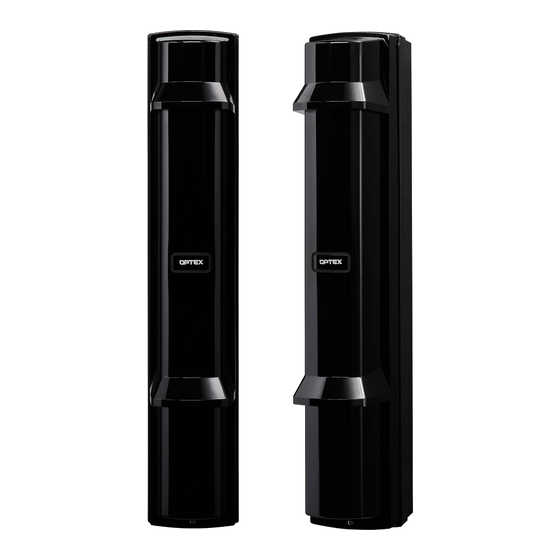
NETWORK PHOTOELECTRIC DETECTOR
NETWORK PHOTOELECTRIC DETECTOR
REDBEAM series
REDBEAM series
1
BEFORE YOUR OPERATION
• Be sure to thoroughly read the instruction manuals of each product before performing wiring.
• The SIP mounting plate for Gang Box, Gasket sheet for Gang Box, and No. 6-32 UNC screws (5/8 inch) (6 pcs) that are described in PIE-1
Manual are not included in this product as they are not required.
• Up to two detectors can be connected to a PIE-1. (Wire size: at least AWG26 (0.13 mm
2
ASSEMBLY
Step 2
Pass the LAN cable
or the external cable
through the grooves
as shown below.
Step 1
Refer to
Step 3
(1) Plug the alarm 10-pin cable to PIE-1.
(2)
(2) Plug the power 2-pin cable to PIE-1.
Use the 24VDC connector.
(3) Set the Selector switch of PIE-1.
(1)
(4)
(4) Plug the CAT5e cable to the
Ethernet connector for PoE of PIE-1.
(3)
(5) Place PIE-1 into the back box.
™
™
Step 1
(1) Open the knockout hole (upper or lower)
of the back box.
Upper
Back box
PIE-1
RBM-60QN-IP
RBM-100QN-IP
RBM-200QN-IP
2
), wire length: 2.5 m (8.2 ft.) max.)
(2) Connect the couduit to the knockout
hole of the back box.
ø 21mm (0.84 inch) hole diameter
Lower
Sponge
Chassis
Note >>
・Run the cables so that
they are not pinched
between the chassis
and back box.
Banding band
Wiring notch
-1-
WIRING DIAGRAM
Detection range
MODEL
60m/200ft.
100m/
2
0
0
m/650ft.
Main unit
Step 4
(1) Mount the sponge.
(2) Mount the chassis.
(3) Mount the main unit.
(4) Wire the sensor.
(5) Connect the alarm 6-pin and power 2-pin cables.
(6) Perform optical adjustment.
(7) Mount the cover.
Caution
Be sure to connect the connector after
cutting all the unnecessary wires.
No.59-1968-0
350ft.
Cover
Advertisement
Table of Contents

Related Manuals for Optex REDBEAM Series


Summary of Contents for Optex REDBEAM Series
- Page 1 No.59-1968-0 WIRING DIAGRAM NETWORK PHOTOELECTRIC DETECTOR NETWORK PHOTOELECTRIC DETECTOR Detection range MODEL ™ ™ RBM-60QN-IP REDBEAM series REDBEAM series 60m/200ft. RBM-100QN-IP 100m/ 350ft. RBM-200QN-IP m/650ft. BEFORE YOUR OPERATION • Be sure to thoroughly read the instruction manuals of each product before performing wiring.
- Page 2 WIRING RECEIVER ONLY TRANSMITTER ONLY <Receiver> <Transmitter> POWER POWER + (Red) (Red) POWER INPUT (1) + POWER INPUT OUTPUT OUTPUT 10.5-30VDC 10.5-30VDC - (Black) - (Black) (2) - (2) - 24VDC 24VDC SPARE SPARE (Orange) (Orange) (4) N.O. (Orange) (Orange) ALARM OUTPUT (5) N.C.
Need help?
Do you have a question about the REDBEAM Series and is the answer not in the manual?
Questions and answers