
Related Manuals for Beckhoff M310


Summary of Contents for Beckhoff M310
- Page 1 Manual Profibus M310/B310 Optional interface for Embedded-PCs CX9020, CX5xx0 and CX20x0 Version: Date: 2016-06-06...
-
Page 3: Table Of Contents
Adding a Profibus slave .................... 53 5.3.3 Creating a virtual slave .................... 55 5.3.4 Setting the address ...................... 56 5.3.5 Creating a PLC project..................... 57 5.3.6 Linking variables ...................... 59 5.3.7 Load configuration to CX .................... 60 5.3.8 Adding a Profibus master.................... 62 Profibus M310/B310 Version: 1.0... - Page 4 6.3.3 Uploading the Configuration .................... 74 Slave............................. 75 6.4.1 Slave-Diagnose........................ 77 6.4.2 Individual diagnostic data.................... 80 6.4.3 DP-V1 communication ..................... 82 6.4.4 DP-V1 error codes ...................... 84 7 Appendix .............................. 85 Accessories .......................... 85 Certifications .......................... 86 Support and Service ........................ 87 Version: 1.0 Profibus M310/B310...
-
Page 5: Foreword
EP0851348, US6167425 with corresponding applications or registrations in various other countries. ® EtherCAT is registered trademark and patented technology, licensed by Beckhoff Automation GmbH, Germany Copyright © Beckhoff Automation GmbH & Co. KG, Germany. The reproduction, distribution and utilization of this document as well as the communication of its contents to others without express authorization are prohibited. -
Page 6: Safety Instructions
All the components are supplied in particular hardware and software configurations appropriate for the application. Modifications to hardware or software configurations other than those described in the documentation are not permitted, and nullify the liability of Beckhoff Automation GmbH & Co. KG. Personnel qualification This description is only intended for trained specialists in control, automation and drive engineering who are familiar with the applicable national standards. -
Page 7: Documentation Issue State
Foreword Documentation issue state Version Modifications First version Profibus M310/B310 Version: 1.0... -
Page 8: Profibus System Overview
• CX20x0 PROFIBUS master (M310) The optional interface M310 is a PROFIBUS master and enables a segment-like construction of control structures in large plants and machines. Further Beckhoff fieldbus components such as Bus Couplers, Bus Terminal Controllers, drive components, etc. can be used with an Embedded PC for configuring control structures. - Page 9 PROFIBUS DP offers short system response times: at a transmission rate of 12 Mbaud, less than 2 ms are required to transmit 512 bits each of input and output data to 32 devices. All Beckhoff PROFIBUS devices feature a high-performance protocol implementation and are certified by the PROFIBUS user organization (PNO).
-
Page 10: Configuration Options
A maximum of 126 devices (master or slaves) can be connected to one bus. A station address between 0 and 99 can be chosen for the Beckhoff PROFIBUS slaves from the IPxxxx-B310, IL230x- B310 and IL230x-C310 series. The specifications for the system configuration contain the number of stations, the assignment of the station addresses to the I/O addresses, data consistency of the I/O data, the format of the diagnostics messages and the bus parameters being used. Every PROFIBUS... - Page 11 Here the cause of an error is related to a single input/output bit (channel), such as a short circuit on output 2 The Beckhoff PROFIBUS slaves from the IPxxxx-B310, IL230x-B310 and IL230x-C310 series support the PROFIBUS DP diagnostic functions. Assessment of the diagnostic data by means of the controller depends on the support for the PROFIBUS master.
- Page 12 This provides protection from project planning errors. Manufacturer-specific identification numbers are issued by the PROFIBUS User Organisation (PNO). The PNO administers the identification numbers along with the basic device data (GSD). Version: 1.0 Profibus M310/B310...
-
Page 13: Communication Protocols And Services
The master distinguishes between the CLEAR state (all outputs are set to the Fail_Safe value) and the OPERATE state (all outputs have the process value). The Master is usually switched into the CLEAR mode when, for instance, the PLC enters STOP. Profibus M310/B310 Version: 1.0... - Page 14 DP connection, so that a manufacturer-specific project planning and diagnostic tool can access the slave data, for example. If two masters are used, please note that they share the bus access, and the temporal conditions are therefore less favorable compared with a single master. Version: 1.0 Profibus M310/B310...
-
Page 15: Technical Data - Profibus
PROFIBUS system overview Technical data - PROFIBUS Optional interface M310 Technical data M310 Fieldbus PROFIBUS DP, DP-V1; DP-V2 (MC) Data transfer rate 9,6k; 19,2k; 93,75k; 187,5k; 500k; 1,5M; 3M; 6M; 12 MBaud Bus interface 1 x D sub-socket, 9-pin Bus devices max. -
Page 16: Connection And Cabling
The Profibus bus line is connected via a 9-pin D sub with the following pin assignment: Assignment Shielding not used RxD/TxD-P not used not used RxD/TxD-N not used cable colors PROFIBUS line D sub B red Pin 3 A green Pin 8 Version: 1.0 Profibus M310/B310... -
Page 17: Cabling
HOFF are used! Wiring errors are avoided, and commissioning is more rapidly completed. Note The BECKHOFF range includes fieldbus cables, power supply cables, sensor cables and accessories such as terminating resistors and T-pieces. Connectors and cables for field as- sembly are nevertheless also available. - Page 18 4. Resistance between B at the start and B at the end of the lead: approx. 0 Ohm 5. Resistance between screen at the start and screen at the end of the lead: approx. 0 Ohm Version: 1.0 Profibus M310/B310...
- Page 19 If these measurements are successful, the cable is okay. If, in spite of this, bus malfunctions still occur, this is usually a result of EMC interference. Observe the installation notes from the PROFIBUS User Organisation (www.profibus.com). Profibus M310/B310 Version: 1.0...
-
Page 20: Topology
• Stubs are to be avoided, and are not permitted above 1.5 Mbaud. • The maximum number of devices is 125 • Interrupting the supply voltages from cable ends by switching off the repeater/slave, or by pulling out the plug, is not permitted. Version: 1.0 Profibus M310/B310... -
Page 21: Twincat Tabs
Further settings for the Profibus master or slave can be implemented under the tabs. Other tabs are displayed, depending on whether the master or slave is selected in the tree view. A Profibus slave and the corresponding tabs are shown as follows in the tree view: Profibus M310/B310 Version: 1.0... - Page 22 PLC program. Double-click on a variable name in the tree view to open the link dialog. The link variables are identified with a small arrow icon. Further information about TwinCAT can be found in the TwinCAT documentation on the Beckhoff website: www.beckhoff.de Version: 1.0...
-
Page 23: Profibus Master
Here you can disable the Profibus device Running No. The Profibus device can be switched off via this tab. A comment field offers the option to add a label, in order to provide additional information on the device. Profibus M310/B310 Version: 1.0... -
Page 24: Ccat Pbm
Any deviations are displayed. Here the PROFIBUS is scanned, and all devices that are found are added to the master. For Beckhoff boxes the configuration is read exactly, for external devices the system searches for the corresponding device master file. -
Page 25: Bus Parameters (Dp)
DpState, which in this case is not 0 for one cycle. A distinction can be made between master functionality (default) and multi- slave. This button is used to optimize the bus parameters. This button is used to set the standard bus parameters. Profibus M310/B310 Version: 1.0... -
Page 26: Startup/Fault Settings
Here you can select whether the watchdog is to be set individually for each slave. If the checkbox is ticked, the watchdog can be set for each slave on the Profibus tab (see: Profibus [} 30]). Version: 1.0 Profibus M310/B310... -
Page 27: Ads
The Profibus master is an ADS device with its own Net ID, which can be modified here. All ADS services (diagnostics, acyclic communication) sent to the Profibus master must use this Net ID and port no. Profibus M310/B310 Version: 1.0... -
Page 28: Dp Diag
Increments if not all slaves exchange data (i.e. DpState is not 0). max./min./actual Cycle-Time: Displays the maximum, minimum and current DP cycle times; only those cycles are taken into account, in which all slaves have exchanged data and no repetitions have occurred. Version: 1.0 Profibus M310/B310... -
Page 29: Box States
TwinCAT tabs 4.2.7 Box States The connected Profibus slaves are listed in the Box States tab. This overview can be used to detect errors such as connection problems at the boxes. Profibus M310/B310 Version: 1.0... -
Page 30: Profibus Slave
Enables editing of Profibus-specific parameter data. The size of the current parameter data is also displayed. The PrmData can usually be set as text (- > PrmData (text)) or for Beckhoff DP slaves partly via the “Beckhoff” tab. Watchdog: Activates the DP watchdog. If the slave does not receive a DP telegram for the duration of the watchdog time with the watchdog switched on, it will automatically exit the data exchange. -
Page 31: Features
WaitPrm state. A restart is only possible through an IO reset or restart of the TwinCAT system). For each slave it can be specified whether, on exiting of Data Exch (DpState not equal 0), its input data should be set to 0 or remain unchanged. Profibus M310/B310 Version: 1.0... -
Page 32: Diag
Repeat-Counter: Number of required repetitions due to missing or disturbed response from the slave. NoAnswer-Counter: Number of telegrams that remained unanswered by the slave. Last DPV1 error: Error-Decode, Error-Class, Error-Code and Error-Code 2 (see description of the DPV1 Error Codes). Version: 1.0 Profibus M310/B310... -
Page 33: Parameterization And Commissioning
Embedded PCs with Profibus interface. The following devices are used in this documentation: • CX2020-M310 (Embedded PC with optional Profibus master interface, D-sub socket, 9-pin) • CX2500-B310 (Embedded PC with fieldbus module CX2500-B310 Profibus slave, D-sub socket, 9-pin) •... - Page 34 Sample: Task cycle time 2 ms, real-time resources 80%. Since in this case the task and the PROFIBUS have to share the bandwidth, exceedance of the real-time resources has a stronger effect than in the case "I/O at task begin": Version: 1.0 Profibus M310/B310...
- Page 35 Outputs and inputs are therefore always one cycle old. For a master that is to be operated in Sync/Freeze mode, the option DP/MC (Equidistant) must be set in the CCAT PBM tab under Operation Mode (see: CCAT PBM [} 24]). Profibus M310/B310 Version: 1.0...
- Page 36 Parameterization and commissioning For a slave that is to be operated in Sync/Freeze mode, the option Sync/Freeze enable must be selected on the Profibus tab (see: Profibus [} 30]). The master always uses group 1 for the Sync/Freeze synchronization. Version: 1.0 Profibus M310/B310...
-
Page 37: Parameterization With Twincat 2
MAC address. The MAC address is located on the side of the device. Search for the devices as follows: 1. Click on File > New in the menu at the top. 2. Click on Choose Target System in the toolbar at the top. 3. Click on Search (Ethernet). Profibus M310/B310 Version: 1.0... - Page 38 (AMS Net ID). Using this procedure you can search for all available devices and also switch between the target systems at any time. Next, you can append the device to the tree view in TwinCAT. Version: 1.0 Profibus M310/B310...
-
Page 39: Adding A Profibus Slave
5. Confirm the request with Yes, in order to look for boxes. Box 1 (CX2500-B310) is integrated. The Insert Module window appears. 6. Add modules such as 1 BYTE Slave-Out/Master-In and 1 BYTE Slave-In/Master-Out for your process image. Profibus M310/B310 Version: 1.0... - Page 40 You can add further variables by right-clicking on the box and then clicking on Append Module in the context menu. In the next step you can extend the process image by creating additional virtual slaves. Or you can set the address, once the slave configuration is complete. Version: 1.0 Profibus M310/B310...
-
Page 41: Creating A Virtual Slave
2. Click on Append Box in the context menu. ð A further box (virtual slave) is created. Variables for the virtual slave can now be created. In the next step you can set the address for the slave. Profibus M310/B310 Version: 1.0... -
Page 42: Setting The Address
3. Enter a value for the Profibus address in the Station No field, e.g. „31“. ð You have set the address successfully. The Profibus master can reach the Profibus slave with the set address. Next, you can create a PLC project for the Profibus slave. Version: 1.0 Profibus M310/B310... -
Page 43: Creating A Plc Project
The file name of the new file is the same as the file name of the PLC project. In the next step you can add the compiled PLC project in the TwinCAT System Manager. Profibus M310/B310 Version: 1.0... - Page 44 The PLC project is added in the tree view under PLC – Configuration. The variables defined in the project are shown under the inputs and outputs. In the next step you can link the variables with the hardware. Version: 1.0 Profibus M310/B310...
-
Page 45: Linking Variables
ð You have successfully linked variables with the hardware. Use Activate Configuration to save and activate the current configuration. The configuration can now be loaded on the CX, in order to automatically start TwinCAT in Run mode, followed by the PLC project. Profibus M310/B310 Version: 1.0... -
Page 46: Load Configuration To Cx
4. Enter the user name and password for the CX in the User Name and Password fields. 5. Click on Apply. The Logon Information window appears. 6. Re-enter the user name and the password and click OK. Version: 1.0 Profibus M310/B310... - Page 47 PLC project will start automatically. Next, the Profibus master can be added in a new project in the System Manager and can then be used to find Profibus slaves that have already been set up. Profibus M310/B310 Version: 1.0...
-
Page 48: Adding A Profibus Master
TwinCAT. Prerequisites for this step: • TwinCAT must be in Config mode. • A selected target system (in this example it is the Embedded PC CX2020-M310) Add a Profibus master as follows: 1. Start the System Manager. 2. In the tree view on the left, right-click on I/O Devices. -
Page 49: Testing Profibus Networking
Profibus slave, if the LED also lights up for the Bus Terminal that is connected to the Bus Coupler. The Profibus master and Profibus slave are then successfully linked with each other. Profibus M310/B310 Version: 1.0... -
Page 50: Turning' Process Data
Swap Word (green) Swap both (blue and selected green) 0x01020304 0x01020304 0x02010403 0x03040102 0x04030201 The data can also be 'turned' in the PLC project, using the command ROR. Example for ST: VarProfibus:=ROR(VarAnalog,8); (*Both variables of type WORD*) Version: 1.0 Profibus M310/B310... -
Page 51: Parameterization With Twincat 3
1. In the menu at the top click on File > New > Project and create a new TwinCAT XAE project. 2. In the tree view on the left click on SYSTEM, and then Choose Target. 3. Click on Search (Ethernet). Profibus M310/B310 Version: 1.0... - Page 52 The new target system and the host name are displayed in the menu bar. Using this procedure you can search for all available devices and also switch between the target systems at any time. Next, you can append the device to the tree view in TwinCAT. Version: 1.0 Profibus M310/B310...
-
Page 53: Adding A Profibus Slave
5. Confirm the request with Yes, in order to look for boxes. Box 1 (CX2500-B310) is integrated. The Insert Module window appears. 6. Add modules such as 1 BYTE Slave-Out/Master-In and 1 BYTE Slave-In/Master-Out for your process image. Profibus M310/B310 Version: 1.0... - Page 54 You can add further variables by right-clicking on the box and then clicking on Add New Item in the context menu. In the next step you can extend the process image by creating additional virtual slaves. Or you can set the address, once the slave configuration is complete. Version: 1.0 Profibus M310/B310...
-
Page 55: Creating A Virtual Slave
2. Click on Add New Item in the context menu. ð A further box (virtual slave) is created. Variables for the virtual slave can now be created. In the next step you can set the address for the slave. Profibus M310/B310 Version: 1.0... -
Page 56: Setting The Address
3. Enter a value for the Profibus address in the Station No field, e.g. „31“. ð You have set the address successfully. The Profibus master can reach the Profibus slave with the set address. Next, you can create a PLC project for the Profibus slave. Version: 1.0 Profibus M310/B310... -
Page 57: Creating A Plc Project
2. In the context menu click on Add New Item and select the Standard PLC Project. 3. In the tree view click on the newly created PLC project, then double-click on MAIN (PRG) under POUs. 4. Write a small program, as shown in the diagram below. Profibus M310/B310 Version: 1.0... - Page 58 ð You have successfully created a PLC project and added the project in TwinCAT. A PLC instance with the variables for the inputs and outputs is created from the PLC project. In the next step you can link the variables with the hardware. Version: 1.0 Profibus M310/B310...
-
Page 59: Linking Variables
ð You have successfully linked variables with the hardware. Use Activate Configuration to save and activate the current configuration. The configuration can now be loaded on the CX, in order to automatically start TwinCAT in Run mode, followed by the PLC project. Profibus M310/B310 Version: 1.0... -
Page 60: Load Configuration To Cx
4. Enter the user name and password for the CX in the User Name and Password fields. 5. Click on Apply. 6. In the tree view on the left right-click on the PLC project under PLC. Version: 1.0 Profibus M310/B310... - Page 61 PLC project will start automatically. Next, the Profibus master can be added in a new project in the System Manager and can then be used to find Profibus slaves that have already been set up. Profibus M310/B310 Version: 1.0...
-
Page 62: Adding A Profibus Master
Prerequisites for this step: • TwinCAT must be in Config mode. • A selected target system (in this example it is the Embedded PC CX2020-M310) Add a Profibus master as follows: 1. Start TwinCAT. 2. In the tree view on the left, right-click on Devices. -
Page 63: Testing Profibus Networking
Profibus slave, if the LED also lights up for the Bus Terminal that is connected to the Bus Coupler. The Profibus master and Profibus slave are then successfully linked with each other. Profibus M310/B310 Version: 1.0... -
Page 64: Turning' Process Data
Swap Word (green) Swap both (blue and selected green) 0x01020304 0x01020304 0x02010403 0x03040102 0x04030201 The data can also be 'turned' in the PLC project, using the command ROR. Example for ST: VarProfibus:=ROR(VarAnalog,8); (*Both variables of type WORD*) Version: 1.0 Profibus M310/B310... -
Page 65: Error Handling And Diagnostics
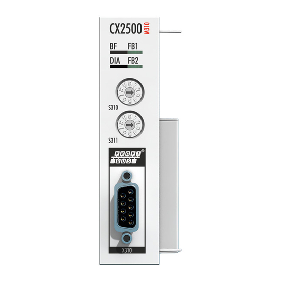
The diagnostic LEDs of a PROFIBUS master and PROFIBUS slaves are described here. The labelling of the diagnostic LEDs on a CX2500 fieldbus module and an Embedded PC with optional interface is identical. The LED description therefore only distinguishes between PROFIBUS master and PROFIBUS slave. M310 (Master) Display Colours... -
Page 66: Error Reactions
DP cycle, until the DP connection has been re-established. At least seven telegrams are sent, in order to re-establish the DP connection. The process usually takes at least 10-20 ms. Version: 1.0 Profibus M310/B310... - Page 67 A watchdog time can be enabled in the slave, in order to monitor the failure of the master or the transfer to the PROFIBUS (see: Profibus [} 30] tab). The watchdog time must be set to at least twice the maximum of the estimated DP cycle and the cycle time (see: CCAT PBM [} 24] tab). Profibus M310/B310 Version: 1.0...
- Page 68 DP connection for the corresponding DP slave has been established, the master cyclically (with the highest priority assigned task) sends one Data_Exchange telegram to each of the corresponding slaves. Version: 1.0 Profibus M310/B310...
-
Page 69: Master
Counter[4] This variable is a timeout counter. The counter is incremented by 1 whenever a timeout occurs on the PROFIBUS. Counter[5-7] These variables are reserved for extensions. DiagFlag: Profibus M310/B310 Version: 1.0... -
Page 70: Ads-Interface
0 (False), the redundancy master is offline. 6.3.1 ADS-Interface ADS NetId of the PROFIBUS interface A NetId is required for the ADS communication. This can be found in the ADS tab of the PROFIBUS interface in the TwinCAT System Manager. Version: 1.0 Profibus M310/B310... - Page 71 Class -1 connection; the DPV1 slot number corresponds to the In- dexGroup, the DPV1 index corresponds to the IndexOffset (see: DPV1 communication [} 73]). ADS-WriteControl An overview of services supported by the Embedded PCs for ADS WriteControl is provided below. Profibus M310/B310 Version: 1.0...
- Page 72 DP slave (Data_Exchange) is removed (with SetPrm,Unlock). RUN (5) 0x00 STOP (6) This will restart the slave after a stop, i.e. the process data connection to the relevant DP slave (Data_Exchange) is re-established (normal DP start-up). Version: 1.0 Profibus M310/B310...
-
Page 73: Dpv1 Communication
If it is also generally necessary to activate the C1 functionality by setting bit 7 in the PrmData byte 0 for the corresponding slave (this is done automatically for those Beckhoff devices that support DPV1). MSAC-C1-Read is shown in ADS-Read, and MSAC-C1-Write is represented in ADS-Write:... -
Page 74: Uploading The Configuration
Data Configuration data of the slave If the device is from another manufacturer, or if the IndexGroup indicates that Beckhoff devices are to behave in exactly the same way as devices from other manufacturers, then the following information is returned in the ADS read response:... -
Page 75: Slave
Error handling and diagnostics Slave Diagnostic variables The slave features various diagnostic variables, which describe the state of the slave and the Profibus and can be linked in the PLC: DpState: Profibus M310/B310 Version: 1.0... - Page 76 The slave was parameterized, but has not yet received a Chk_Cfg telegram. Slave waiting for parameter: The slave was not yet parameterized and is waiting for a Set_Prm (Lock) telegram. Slave waiting for baud rate: The baud rate was not set. Version: 1.0 Profibus M310/B310...
-
Page 77: Slave-Diagnose
DP diagnostic data from the slave. This does not affect the Data-Exchange cycle in the Beckhoff DP master, because the DP diagnostic telegram is sent at the end of the cyclic Data-Exchange cycle, and before the beginning of the next cycle. If the DP diagnostic data read from the slave has changed from its previous state, the DP master sets the ExtDiagFlag variable, which can be linked to a variable in the controller program. - Page 78 (byte 0: DPV1 service (bit 7 is set, thus indicating an error), byte 1: Error_Decode, byte 2: Error_Code_1 (Error_Class/Error_Code), byte 3: Error_Code_2), see description of the DPV1 error codes [} 84] 27-31 reserved for extensions from 32 DP diagnostic data There follows a description of the DP diagnostic data Version: 1.0 Profibus M310/B310...
- Page 79 0 = manufacturer-specific diagnosis (DPV1 is not supported) or DPV1 diagnosis (DPV1 is supported (DPV1_Enable = 1) in associated GSD file) Module diagnosis Channel diagnosis Revision number Manufacturer-specific diagnosis The structure of the manufacturer-specific diagnosis may be found in the documentation for the DP slave. Profibus M310/B310 Version: 1.0...
-
Page 80: Individual Diagnostic Data
0x02.3 reserved 0x02.4 reserved 0x02.5 reserved 0x02.6 reserved 0x02.7 ExtDiagOverflow: too much extended data present 0x03 MasterAdd: station address of master with which slave is exchanging data 0x04,0x05 IdentNumber ab 0x06 Device-specific diagnostic data (extended DiagData) Version: 1.0 Profibus M310/B310... - Page 81 6. The ADS parameters for the read process are identical. Input parameters Description NETID local NetId of the Profibus device PORT number 0x1000+slave address IDXGRP 16#F481 IDXOFFS max. 244 SRCADDR Pointer to diagnostic data Profibus M310/B310 Version: 1.0...
-
Page 82: Dp-V1 Communication
If it is also generally necessary to activate the C1 functionality by setting bit 7 in the PrmData byte 0 (see the slave's PROFIBUS tab) for the corresponding slave (this is done automatically for those Beckhoff devices that support DPV1). - Page 83 Result of the read: 0 = no error, otherwise: bits 0-15 = standard ADS error codes, bits 16-23 = Error_Code_1, bits 24-31 = Error_Code_2, See: DP-V1 error codes [} 84]. Length (LENGTH) Length of the data that has been read Profibus M310/B310 Version: 1.0...
-
Page 84: Dp-V1 Error Codes
Access, State Conflict 0x06 Access, Access Denied 0x07 Access, Invalid Range 0x08 Access, Invalid Parameter 0x09 Access, Invalid Type 0x0C 0x00 Resource, Read Constrain Conflict 0x01 Resource, Write Constrain Conflict 0x02 Resource, Busy 0x03 Resource, Unavailable Version: 1.0 Profibus M310/B310... -
Page 85: Appendix
Synthetic fiber-optic cable, core ø 1000 μm, PU coating ø 5.5 mm, Kevlar strain relief Z1102 as Z1101, on drum, length = 500 m Z1121 Synthetic fiber optic cable, 1000 μm core, 2-core, PU coating, diameter 5.5 mm Profibus M310/B310 Version: 1.0... -
Page 86: Certifications
All products of the Embedded PC family are CE, UL and EAC certified. Since the product family is continuously developed further, we are unable to provide a full listing here. The current list of certified products can be found at www.beckhoff.com. FCC Approvals for the United States of America... -
Page 87: Support And Service
Beckhoff's branch offices and representatives Please contact your Beckhoff branch office or representative for local support and service on Beckhoff products! The addresses of Beckhoff's branch offices and representatives round the world can be found on her internet pages: http://www.beckhoff.com You will also find further documentation for Beckhoff components there.
Need help?
Do you have a question about the M310 and is the answer not in the manual?
Questions and answers