Table of Contents
Advertisement
Quick Links
Advertisement
Table of Contents

Subscribe to Our Youtube Channel
Related Manuals for Beckhoff CX2500-310 Series


Summary of Contents for Beckhoff CX2500-310 Series
- Page 1 Manual | EN CX2500-x310 PROFIBUS Fieldbus Module 2024-11-20 | Version: 1.0...
-
Page 3: Table Of Contents
Table of content Table of content 1 Foreword .............................. 5 Notes on the documentation ...................... 5 Safety instructions .......................... 6 Documentation issue state ........................ 7 2 Product overview ............................ 8 Intended use ............................. 8 Fieldbus module CX2500-M310/B310 .................... 9 Configuration options ........................ 11 Communication protocols and services .................. - Page 4 Table of content 6.3.8 Load configuration to CX.................... 56 6.3.9 Adding a Profibus master.................... 58 6.3.10 Testing Profibus networking..................... 59 6.3.11 'Turning' process data ...................... 60 Parameterization with TwinCAT 3 .................... 61 6.4.1 Searching for target systems ................... 61 6.4.2 Adding a Profibus slave ....................
-
Page 5: Foreword
EP1590927, EP1789857, EP1456722, EP2137893, DE102015105702 with corresponding applications or registrations in various other countries. ® EtherCAT is a registered trademark and patented technology, licensed by Beckhoff Automation GmbH, Germany Copyright © Beckhoff Automation GmbH & Co. KG, Germany. The reproduction, distribution and utilization of this document as well as the communication of its contents to others without express authorization are prohibited. -
Page 6: Safety Instructions
All the components are supplied in particular hardware and software configurations appropriate for the application. Modifications to hardware or software configurations other than those described in the documentation are not permitted, and nullify the liability of Beckhoff Automation GmbH & Co. KG. Personnel qualification This description is only intended for trained specialists in control, automation and drive engineering who are familiar with the applicable national standards. -
Page 7: Documentation Issue State
Foreword Documentation issue state Version Modifications First version CX2500-x310 Version: 1.0... -
Page 8: Product Overview
Product overview Product overview Intended use The CX20x0 device series is a modular control system designed for DIN rail installation. The system is scalable, so that the required modules can be assembled and installed in the control cabinet or terminal box as required. -
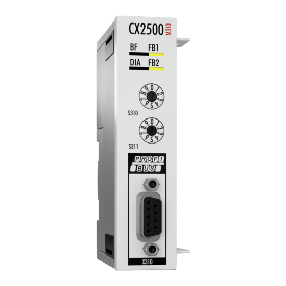
Page 9: Fieldbus Module Cx2500-M310/B310
The fieldbus module CX2500-M310 is a PROFIBUS master and enables a segment-like construction of control structures in large plants and machines. Further Beckhoff fieldbus components such as Bus Couplers, Bus Terminal Controllers, drive components, etc. can be used with an Embedded PC for configuring control structures. - Page 10 PROFIBUS DP offers short system response times: at a transmission rate of 12 Mbaud, less than 2 ms are required to transmit 512 bits each of input and output data to 32 devices. All Beckhoff PROFIBUS devices feature a high-performance protocol implementation and are certified by the PROFIBUS user organization (PNO).
-
Page 11: Configuration Options
A maximum of 126 devices (master or slaves) can be connected to one bus. A station address between 0 and 99 can be chosen for the Beckhoff PROFIBUS slaves from the IPxxxx-B310, IL230x- B310 and IL230x-C310 series. The specifications for the system configuration contain the number of stations, the assignment of the station addresses to the I/O addresses, data consistency of the I/O data, the format of the diagnostics messages and the bus parameters being used. Every PROFIBUS... - Page 12 Here the cause of an error is related to a single input/output bit (channel), such as a short circuit on output 2 The Beckhoff PROFIBUS slaves from the IPxxxx-B310, IL230x-B310 and IL230x-C310 series support the PROFIBUS DP diagnostic functions. Assessment of the diagnostic data by means of the controller depends on the support for the PROFIBUS master.
- Page 13 Product overview associated DP slaves into a safe state as soon as one DP slave is no longer ready for the transfer of user data. The DPM1 then switches into the Clear state. If the parameter is False then the DPM1 remains in the operating state even after a fault, and the user can himself specify the system's reaction.
-
Page 14: Communication Protocols And Services
Product overview Communication protocols and services In PROFIBUS DP systems a master (PLC, PC, etc.) usually communicates with many slaves (I/Os, drives, etc.); only the master actively accesses the bus (by sending unsolicited telegrams), while a DP slave only sends telegrams when requested by the master. PROFIBUS DP •... - Page 15 Product overview • Class 1 and Class 2 DP Masters The Class 1 master refers to the controller that carries out cyclic I/O data exchange with the slaves, while a Class 2 master is a B&B device that generally only has read access to the slaves' I/O data. PROFIBUS DPV1 PROFIBUS DPV1 refers primarily to the acyclic read and write telegrams, with which data sets in the slave are acyclically accessed.
-
Page 16: Technical Data - Profibus
Product overview Technical data - PROFIBUS Dimensions Version: 1.0 CX2500-x310... - Page 17 Product overview CX2500-M310 Technical data CX2500-M310 Fieldbus PROFIBUS DP, DP-V1; DP-V2 (MC) in preparation Data transfer rates 9,6k; 19,2k; 93,75k; 187,5k; 500k; 1,5M; 3M; 6M; 12 MBaud Bus interface 1 x D-sub socket, 9-pin Bus devices max. 125 with repeater max.
-
Page 18: Unpacking And Transport
5. Check the contents for visible shipping damage. 6. If you notice any shipping damage or inconsistencies between the contents and your order, you should notify Beckhoff Service. Shipping and relocation Despite the robust design of the unit, the components are sensitive to strong vibrations and impacts. -
Page 19: Mounting And Wiring
Mounting and wiring Mounting and wiring Installing the extension module at the CX20x0 system Damage to the contacts Incorrect installation may result in damage to the contacts of the fieldbus modules. The fieldbus modules may only be attached on the left-hand side of the basic CPU module. A maximum of four fieldbus modules can be attached to the basic CPU module via the internal PCI Express bus. - Page 20 Mounting and wiring ð The fieldbus module has been installed successfully, if the individual modules were connected straight and flush. Next, you can install the bar clips, thereby reinforcing interlocking of the modules. Version: 1.0 CX2500-x310...
-
Page 21: Installing The Bar Clips
Mounting and wiring Installing the bar clips Installing the bar clips Usually, the connection between the modules is strong enough. However, the basic CPU module and the fieldbus modules may be subjected to shocks, vibrations or other impacts. The modules can be securely connected to one another with the aid of bar clips. -
Page 22: Installation On The Mounting Rail
Mounting and wiring Installation on the mounting rail Installation position and minimum distances The modules or devices may overheat, if the installation position is incorrect or the minimum distances are not adhered to. The devices may only be operated at ambient temperatures up to 60 °C. Ensure adequate ventilation. - Page 23 Mounting and wiring Installation on the mounting rail Avoid damage Do not use force or excessive pressure when installing the devices on the mounting rail. The CX20x0 can easily be installed on the mounting rail. The housing is designed such that it can be pushed against the mounting rail and engaged on it.
- Page 24 Mounting and wiring 2. Position the devices at the front of the mounting rail. Gently push the devices onto the mounting rail until you can hear a click and the devices are engaged. 3. Then lock the latches again. ð The devices are now installed successfully. Verify that the devices are installed correctly and that all devices are engaged on the mounting rail.
-
Page 25: Profibus Connection
Mounting and wiring Profibus Connection Nine-pin D sub Pin 6 transfers 5 V pin 5 transfers GND for the active termination resistor. These must never be used for other functions, as this can lead to destruction of the device. Pins 3 and 8 transfer the PROFIBUS signals. These must never be swapped over, as this will prevent communication. -
Page 26: Cabling
Pre-assembled cable from BECKHOFF Installation is made a great deal more straightforward if pre-assembled cables from BECKHOFF are used! Wiring errors are avoided, and commissioning is more rapidly completed. The BECKHOFF range includes fieldbus cables, power supply cables, sensor cables and accessories such as terminating resistors and T-pieces. - Page 27 Mounting and wiring The following diagram shows the cabling between two stations, as well as the D sub connection assignment: Termination resistors In systems with more than two stations all devices are wired in parallel. It is essential that the bus cables are terminated with resistors at the conductor ends in order to avoid reflections and associated transmission problems.
- Page 28 Mounting and wiring If these measurements are successful, the cable is okay. If, in spite of this, bus malfunctions still occur, this is usually a result of EMC interference. Observe the installation notes from the PROFIBUS User Organisation (www.profibus.com). Version: 1.0 CX2500-x310...
-
Page 29: Topology
Mounting and wiring Topology • A bus segment may consist of a maximum of 32 devices (including the repeaters). • The maximum conductor length of a segment depends on the transmission speed in use and on the quality of the bus cables being used. •... -
Page 30: Twincat Tabs
TwinCAT tabs TwinCAT tabs In TwinCAT, information and settings for the Profibus interface are added under tabs. The main TwinCAT tabs are described in this section. In addition, the section illustrates how the Profibus interface is displayed in the tree view under TwinCAT. The tree view and the tabs for a Profibus interface are identical under TwinCAT2 and TwinCAT3. - Page 31 PLC program. Double-click on a variable name in the tree view to open the link dialog. The link variables are identified with a small arrow icon. Further information about TwinCAT can be found in the TwinCAT documentation on the Beckhoff website: www.beckhoff.com CX2500-x310 Version: 1.0...
-
Page 32: Profibus Master
TwinCAT tabs Profibus master 5.2.1 General The General tab contains general information for a Profibus device, including name, type and ID. Description Name of the Profibus device Type of the Profibus device Here you can add a comment (e.g. notes relating to the system component) Here you can disable the Profibus device Running No. -
Page 33: Ccat Pbm
Any deviations are displayed. Here the PROFIBUS is scanned, and all devices that are found are added to the master. For Beckhoff boxes the configuration is read exactly, for external devices the system searches for the corresponding device master file. -
Page 34: Bus Parameters (Dp)
TwinCAT tabs 5.2.3 Bus Parameters (DP) Description The Slot Time indicates how long the DP master will wait for a response from the DP slave before it sends either a repetition or the next telegram. The minimum Tsdr indicates the minimum length of time for which the DP slave will wait with a response. -
Page 35: Startup/Fault Settings
TwinCAT tabs 5.2.4 Startup/Fault settings Description The DP master changes automatically into the clear mode (the outputs of the slaves are set either to 0 or to the fail-safe value) when it ceases to receive an interrupt from the associated task (e.g. a PLC breakpoint has been reached, or the system has crashed). -
Page 36: Ads
TwinCAT tabs 5.2.5 The Profibus master is an ADS device with its own Net ID, which can be modified here. All ADS services (diagnostics, acyclic communication) sent to the Profibus master must use this Net ID and port no. Version: 1.0 CX2500-x310... -
Page 37: Dp Diag
TwinCAT tabs 5.2.6 DP diag Any problems with the cabling and the DP cycle times are displayed here. Description detected bus errors: Displays the number of bus errors detected. If this counter is not 0, the cabling should be checked, if no PROFIBUS plug connectors were unplugged or connected. - Page 38 TwinCAT tabs The connected Profibus slaves are listed in the Box States tab. This overview can be used to detect errors such as connection problems at the boxes. Version: 1.0 CX2500-x310...
-
Page 39: Profibus Slave
Enables editing of Profibus-specific parameter data. The size of the current parameter data is also displayed. The PrmData can usually be set as text (- > PrmData (text)) or for Beckhoff DP slaves partly via the “Beckhoff” tab. Watchdog: Activates the DP watchdog. If the slave does not receive a DP telegram for the duration of the watchdog time with the watchdog switched on, it will automatically exit the data exchange. -
Page 40: Features
TwinCAT tabs 5.3.2 Features Description Here you can set whether the slave should continue to send data (Stay in Data Exch), even if it does not respond or respond erratically. In this case the data exchange remains active until the slave fails to respond correctly within the watchdog time (watchdog function is enabled, see Profibus tab of the slave). -
Page 41: Diag
TwinCAT tabs 5.3.3 Diag This tab offers an overview of the slave state and the Profibus connection. Here the diagnostic data of the preceding tabs can be displayed in consolidated form. The following and further important information can be viewed here: BoxState: The current DpState is displayed here. -
Page 42: Parameterization And Commissioning
• BK3100 (Profibus slave, D-sub socket, 9-pin) The TwinCAT 2 or TwinCAT 3 software is used for configuring the devices. For further information see the TwinCAT 2 and TwinCAT 3 documentation, which is available from the Beckhoff website: www.beckhoff.de DIP switch The Profibus fieldbus modules CX2500-M310 and CX2500-B310 feature two 10-pin address selection switches. -
Page 43: Synchronizing Profibus
Parameterization and commissioning Synchronizing Profibus In TwinCAT Run mode the Profibus master is always synchronized with the highest priority task, with which variables are linked. Once the mapping was created, the cycle time of the corresponding task is displayed under Cycle Time on the CCAT PBM tab of the master. It is possible to set for the task whether the "I/O at task begin"... - Page 44 Parameterization and commissioning This case would still not be a problem, because the DP cycle was completed within the available time. If the setting I/O at task begin is not activated, the sequence is somewhat more critical. The next example shows the effects.
- Page 45 Parameterization and commissioning Comparison of I/O at task start and I/O not at task start The advantage of the I/O at task begin setting is that the task and the DP cycle do not have to share the available bandwidth. The DP cycle starts very constant (the jitter corresponds to the TwinCAT jitter). If the setting I/O at task begin is not activated, it can easily happen that a DP cycle is omitted, and the temporal constancy of the DP cycle additionally depends on the jitter of the task processing.
-
Page 46: Parameterization With Twincat 2
Parameterization and commissioning Parameterization with TwinCAT 2 This section illustrates how Profibus devices can be parameterized with the aid of TwinCAT 2. A total of three devices are used for the example, including a Profibus master, to which two Profibus slaves are connected. - Page 47 Parameterization and commissioning 4. Type the host name or the IP address of the device into the Enter Host Name / IP box and press [Enter]. 5. Mark the device found and click on Add Route. The Logon Information window appears. 6.
-
Page 48: Adding A Profibus Slave
Parameterization and commissioning 6.3.2 Adding a Profibus slave The example shows a CX2020 Profibus slave with CX2500-B310 fieldbus module, connected to the Profibus master. In order to ensure that the Profibus slave is configured and subsequently detected by the Profibus master with all inputs and outputs, the Profibus slave first must be added in TwinCAT. - Page 49 Parameterization and commissioning 7. Click on Cancel to close the Insert Module window. 8. Confirm the request whether to enable FreeRun with Yes. ð The Profibus slave was successfully added in TwinCAT 2 and is displayed in the tree view with the inputs and outputs.
-
Page 50: Creating A Virtual Slave
Parameterization and commissioning 6.3.3 Creating a virtual slave Additional virtual slaves can be created on the same hardware interface. This enables more data to be exchanged with a Profibus master, or a connection with a second Profibus master can be established. Each virtual slave is assigned a dedicated address via TwinCAT and is configured like an independent device for the Profibus master. -
Page 51: Setting The Address
Parameterization and commissioning 6.3.4 Setting the address Once the Profibus slave was successfully added in TwinCAT, the address of the Profibus slave can be set. Devices with a DIP switch have a preset address. The address on the DIP switch must match the address set in TwinCAT. -
Page 52: Setting The Address With A Dip Switch
Parameterization and commissioning 6.3.5 Setting the address with a DIP switch To ensure that the address set via the address selection switch is used, the corresponding setting must be enabled in TwinCAT. The corresponding setting in TwinCAT is only active, if the Profibus device has an address selection switch. Prerequisites for this step: •... -
Page 53: Creating A Plc Project
Parameterization and commissioning 6.3.6 Creating a PLC project Use PLC Control to create a PLC project. The next steps describe how to create a PLC project in TwinCAT and add it in the tree view. Prerequisites for this step: • An Embedded PC, added in TwinCAT. Create a PLC project as follows: 1. - Page 54 Parameterization and commissioning Adding a PLC project The PLC project can be added in the System Manager. The newly created variables from a PLC project are integrated in the System Manager and can be linked with the inputs and outputs of the hardware. Prerequisites for this step: •...
-
Page 55: Linking Variables
Parameterization and commissioning 6.3.7 Linking variables Once the PLC project was successfully added in the System Manager, you can link the newly created input and output variables from the PLC project with the inputs and outputs of your devices. Prerequisites for this step: •... -
Page 56: Load Configuration To Cx
Parameterization and commissioning 6.3.8 Load configuration to CX Once all variables are linked, the configuration can be saved and loaded on the CX. This has the advantage that the PLC project is loaded and started automatically when the CX is switched on. The start of the previously created PLC project can thus be automated. - Page 57 Parameterization and commissioning 7. In the tree view on the left click on PLC – Configuration, then on the PLC Settings (Target) tab. 8. Select the Start PLC under Boot Project and click on Apply. 9. Start PLC Control and open the PLC project. 10.
-
Page 58: Adding A Profibus Master
Parameterization and commissioning 6.3.9 Adding a Profibus master The Profibus master is added with the TwinCAT System Manager, like the other devices. The attached master can then be used to find all connected slaves. The following section illustrates how to add a Profibus master in TwinCAT. -
Page 59: Testing Profibus Networking
Parameterization and commissioning 6.3.10 Testing Profibus networking The Profibus networking between a Profibus master and a Profibus slave can be tested with TwinCAT. Select the Bus Coupler (BK3100) as Profibus slave for the test. During the test an LED is linked to the Bus Terminal, which is connected to the Profibus slave. -
Page 60: Turning' Process Data
Parameterization and commissioning 6.3.11 'Turning' process data The process data are transferred in Intel format as standard. If the data are required in Motorola format, they have to be 'turned' accordingly. This step illustrates how to 'turn' the data in TwinCAT. If the standard format is required, you can skip this step. -
Page 61: Parameterization With Twincat 3
Parameterization and commissioning Parameterization with TwinCAT 3 This section illustrates how Profibus devices can be parameterized with the aid of TwinCAT 3. A total of three devices are used for the example, including a Profibus master, to which two Profibus slaves are connected. - Page 62 Parameterization and commissioning 4. Type the host name or the IP address of the device into the Enter Host Name / IP box and press [Enter]. 5. Mark the device found and click on Add Route. The Logon Information window appears. Enter the user name and password for the CX in the User Name and Password fields and click OK.
-
Page 63: Adding A Profibus Slave
Parameterization and commissioning 6.4.2 Adding a Profibus slave The example shows a CX2020 Profibus slave with CX2500-B310 fieldbus module, connected to the Profibus master. In order to ensure that the Profibus slave is configured and subsequently detected by the Profibus master with all inputs and outputs, the Profibus slave first must be added in TwinCAT. - Page 64 Parameterization and commissioning 7. Click on Cancel to close the Insert Module window. 8. Confirm the request whether to enable FreeRun with Yes. ð The Profibus slave was successfully added in TwinCAT 3 and is displayed in the tree view with the inputs and outputs.
-
Page 65: Creating A Virtual Slave
Parameterization and commissioning 6.4.3 Creating a virtual slave Additional virtual slaves can be created on the same hardware interface. This enables more data to be exchanged with a Profibus master, or a connection with a second Profibus master can be established. Each virtual slave is assigned a dedicated address via TwinCAT and is configured like an independent device for the Profibus master. -
Page 66: Setting The Address
Parameterization and commissioning 6.4.4 Setting the address Once the Profibus slave was successfully added in TwinCAT, the address of the Profibus slave can be set. Devices with a DIP switch have a preset address. The address on the DIP switch must match the address set in TwinCAT. -
Page 67: Setting The Address With A Dip Switch
Parameterization and commissioning 6.4.5 Setting the address with a DIP switch To ensure that the address set via the address selection switch is used, the corresponding setting must be enabled in TwinCAT. The corresponding setting in TwinCAT is only active, if the Profibus device has an address selection switch. Prerequisites for this step: •... - Page 68 Parameterization and commissioning ð You have set the address successfully, and the Profibus slave will use the set address from now on. You can now create further PDOs. Version: 1.0 CX2500-x310...
-
Page 69: Creating A Plc Project
Parameterization and commissioning 6.4.6 Creating a PLC project The next steps describe how to create a PLC project in TwinCAT and add it in the tree view. Prerequisites for this step: • A newly created TwinCAT XAE project. Create a PLC project as follows: 1. - Page 70 Parameterization and commissioning 5. In the tree view right-click on the PLC project, then click on Build in the context menu. ð You have successfully created a PLC project and added the project in TwinCAT. A PLC instance with the variables for the inputs and outputs is created from the PLC project.
-
Page 71: Linking Variables
Parameterization and commissioning 6.4.7 Linking variables Once the PLC project was successfully added in the System Manager, you can link the newly created input and output variables from the PLC project with the inputs and outputs of your hardware. Prerequisites for this step: •... -
Page 72: Load Configuration To Cx
Parameterization and commissioning 6.4.8 Load configuration to CX Once variables are linked, the configuration can be saved and loaded on the CX. This has the advantage that the PLC project is loaded and started automatically when the CX is switched on. The start of the previously created PLC project can thus be automated. - Page 73 Parameterization and commissioning 7. In the context menu click on Autostart Boot Project. The setting is selected 8. Right-click on the project folder in the tree view. 9. In the context menu click on Auto Save to Target as Archive. The setting is selected.
-
Page 74: Adding A Profibus Master
Parameterization and commissioning 6.4.9 Adding a Profibus master The Profibus master is added with the TwinCAT System Manager, like the other devices. The attached master can then be used to find all connected slaves. The following section illustrates how to add a Profibus master. -
Page 75: Testing Profibus Networking
Parameterization and commissioning 6.4.10 Testing Profibus networking The Profibus networking between a Profibus master and a Profibus slave can be tested with TwinCAT. Select the Bus Coupler (BK3100) as Profibus slave for the test. During the test an LED is linked to the Bus Terminal, which is connected to the Profibus slave. -
Page 76: Turning' Process Data
Parameterization and commissioning 6.4.11 'Turning' process data The process data are transferred in Intel format as standard. If the data are required in Motorola format, they have to be 'turned' accordingly. This step illustrates how to 'turn' the data in TwinCAT. If the standard format is required, you can skip this step. -
Page 77: Error Handling And Diagnostics
Error handling and diagnostics Error handling and diagnostics The Error reactions section describes the reactions that will be given to slaves that do not answer or that answer incorrectly, to a PLC stop or at start-up. The Master section describes the different diagnostic variables and how the diagnostic data can be read. The Slave section describes the diagnostic information, which indicated the state of the Profibus slave. -
Page 78: Error Reactions
Error handling and diagnostics Error Reactions Failure of a slave If a slave does not respond or the response is faulty, the master repeats the telegram several times, up to the Max Retry limit (see: Bus Parameters (DP) [} 34]). If a faulty telegram is received, the master repeats the telegram immediately. - Page 79 Error handling and diagnostics If the DP connection is not to be interrupted until the watchdog time has elapsed (Star in Data Exch for WD time, Features tab of the slave), the system waits for a correct response for the watchdog time set for the slave.
- Page 80 Error handling and diagnostics Failure of the PLC/IO task A distinction is made between a PLC stop, reaching a break point and a task stop (the I/O task and NC task are only stopped when the entire system stops). In the case of a PLC stop, the output data is set to 0 by the PLC, whereas when a breakpoint is reached the data initially remains unchanged.
-
Page 81: Master
Error handling and diagnostics Master Diagnostic variables The master possesses a variety of diagnostic variables that describe the state of the master and of the Profibus. They can be linked in the PLC: CdlInfo: Variable Description cycleCounter Is incremented at the end of each PROFIBUS cycle in order that this variable can indicate whether the last cycle was completed before the task was started. -
Page 82: Ads-Interface
Error handling and diagnostics Variable Description DiagFlag Indicates whether the master diagnostic information has changed. In this case the control program reads the information via ADS, and the variable "DiagFlag" is then reset. 0 = diagnostic data unchanged. 1 = diagnostic data have changed. Use ADS Read to read the data. GlobalState: Variable Description... - Page 83 Error handling and diagnostics ADS-Interface All acyclic data are transferred to or from the Embedded PCs with ADS Read, ADS Write or ADS Write Control. The Profibus interface of the Embedded PCs has a dedicated Net ID and supports the following ports: Port Description...
- Page 84 Error handling and diagnostics Table 4: ADS-WriteControl for addressing a configured PROFIBUS device (port 0x1000-0x107E) AdsState DeviceState State of the slave Description STOP (6) 0x00 RUN (5) This will stop the slave, i.e. the process data connection to the relevant DP slave (Data_Exchange) is removed (with SetPrm,Unlock). RUN (5) 0x00 STOP (6)
-
Page 85: Dpv1 Communication
If it is also generally necessary to activate the C1 functionality by setting bit 7 in the PrmData byte 0 for the corresponding slave (this is done automatically for those Beckhoff devices that support DPV1). MSAC-C1-Read is shown in ADS-Read, and MSAC-C1-Write is represented in ADS-Write:... -
Page 86: Uploading The Configuration
Data Configuration data of the slave If the device is from another manufacturer, or if the IndexGroup indicates that Beckhoff devices are to behave in exactly the same way as devices from other manufacturers, then the following information is returned in the ADS read response:... -
Page 87: Slave
Error handling and diagnostics Slave Diagnostic variables The slave features various diagnostic variables, which describe the state of the slave and the Profibus and can be linked in the PLC: DpState: CX2500-x310 Version: 1.0... - Page 88 Error handling and diagnostics Value Description No Error: Station is in data exchange. Station deactivated: The slave was deactivated. Station not exists: Slave does not respond. Check whether the slave is switched on, the cabling is OK and the station address is correct.
-
Page 89: Slave-Diagnose
DP diagnostic data from the slave. This does not affect the Data-Exchange cycle in the Beckhoff DP master, because the DP diagnostic telegram is sent at the end of the cyclic Data-Exchange cycle, and before the beginning of the next cycle. If the DP diagnostic data read from the slave has changed from its previous state, the DP master sets the ExtDiagFlag variable, which can be linked to a variable in the controller program. - Page 90 Error handling and diagnostics Offset Meaning Slave statistics Receive Error Counter (WORD): The number of faulty telegrams occurring while communicating with this slave. Repeat counter[8] (WORD): The repeat counters indicate how many repeats have had to be made, and how often. Repeat Counter[0] indicates how often it has been necessary to repeat a telegram for this slave once, Repeat Counter[1] shows how often a telegram for this slave has had to be repeated twice, and so on.
- Page 91 Error handling and diagnostics Offset Meaning 0x00.0 StationNonExistent: slave did not reply to the last telegram 0x00.1 StationNotReady: slave still processing the Set_Prm / Chk_Cfg telegram 0x00.2 CfgFault: slave signaling a configuration error 0x00.3 ExtDiag: extended DiagData available and valid 0x00.4 NotSupported: slave does not support a feature requested via Set_Prm or Global_Control...
-
Page 92: Individual Diagnostic Data
Error handling and diagnostics 7.4.2 Individual diagnostic data The controller enables sending of diagnostic data from the PLC. You can write your own diagnostic message for the master and fill it individually with data (see Device-specific diagnostic data below). DP Diagnostic Data (DiagData) Transmission of the diagnostic telegram A diagnostic telegram is only transferred to the controller when the diagnostic data have changed. - Page 93 Error handling and diagnostics Device-specific diagnostic data Transmission of user-specific diagnostic data Byte 0 of the data must contain a 0x08. Bytes 1 to 5 are overwritten by the CX. Byte 6 and higher can contain your own diagnostic data. Make sure that your own diagnostic data conforms to the PROFIBUS standard for user-specific diagnosis.
-
Page 94: Dp-V1 Communication
If it is also generally necessary to activate the C1 functionality by setting bit 7 in the PrmData byte 0 (see the slave's PROFIBUS tab) for the corresponding slave (this is done automatically for those Beckhoff devices that support DPV1). - Page 95 Error handling and diagnostics ADS read indication parameter Meaning Source-Net-ID (NETID) Net-ID of the slave (see the device’s ADS tab) Source-Port (PORT) 0x1000+slave address Invoke-ID (INVOKEID) A unique number that must reappear in the response IndexGroup (IDXGRP) Slot number (DPV1 parameter) IndexOffset (IDXOFFS) Index (DPV1 parameter) Length (LENGTH)
-
Page 96: Dp-V1 Error Codes
Error handling and diagnostics 7.4.4 DP-V1 error codes In the event of an incorrect DPV1 access, the slave replies with 4 bytes of data (any values that are not described here are not defined in the DPV1 standard, and are therefore to be found in the slave's manual). byte 0 DPV1 service 0xD1... -
Page 97: Disassembly And Disposal
Disassembly and disposal Disassembly and disposal The disassembly of a CX20x0 hardware configuration with system interfaces takes place in 3 steps 1. Switching off and disconnecting the power supply Before a CX20x0 system can be dismantled, the system should be switched off, and the power supply should be disconnected. - Page 98 Subsequently, the system interfaces can be separated again. NOTICE Do not use force to open the device! Opening the module housing by force would destroy it. The devices may only be opened by Beckhoff service personnel. Version: 1.0...
-
Page 99: Appendix
Appendix Appendix Accessories Cables and connectors for the connection of the Profibus components. Connector Item number Description ZB3100 9-pin D sub connector up to 12 Mbaud, with switchable termination resistor ZB3101 9-pin D sub connector up to 12 Mbaud, with programming interface ZB3102 9-pin D sub connector up to 12 Mbaud, with switchable... -
Page 100: Certifications
All products of the Embedded PC family are CE, UL and EAC certified. Since the product family is continuously developed further, we are unable to provide a full listing here. The current list of certified products can be found at www.beckhoff.com. FCC Approvals for the United States of America... -
Page 101: Support And Service
Beckhoff's branch offices and representatives Please contact your Beckhoff branch office or representative for local support and service on Beckhoff products! The addresses of Beckhoff's branch offices and representatives round the world can be found on her internet pages: http://www.beckhoff.com You will also find further documentation for Beckhoff components there. - Page 103 More Information: www.beckhoff.com/CX2500-M310 Beckhoff Automation GmbH & Co. KG Hülshorstweg 20 33415 Verl Germany Phone: +49 5246 9630 info@beckhoff.com www.beckhoff.com...
Need help?
Do you have a question about the CX2500-310 Series and is the answer not in the manual?
Questions and answers