
Subscribe to Our Youtube Channel
Related Manuals for Beckhoff M2510


Summary of Contents for Beckhoff M2510
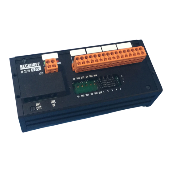
- Page 1 M2510 Analog Input Beckhoff II/O Lightbus System M2510 Analog Input Technical Description Eiserstraße 5 Phone: +495246/963-0 33415 Verl Fax: +495246/963-149 Date: 20.08.93 Version : 2.0 Page 1 of 11...
-
Page 2: Table Of Contents
M2510 Analog Input Beckhoff II/O Lightbus System Table of Contents 1. Function Description - Hardware..........3 2. Function Description - Software ............5 3. Technical Data.................6 4. Installation Notes................7 5. Connections Table.................11 Page 2 of 11 Version : 2.0 Date: 20.08.93... -
Page 3: Function Description - Hardware
Beckhoff II/O Lightbus System 1. Function Description - Hardware M2510 General The module M2510 is an input module used in the II/O system. By ADU four analog input values in the form 0 to +10V 0 to 1V 0 to 20mA... - Page 4 M2510 Analog Input Beckhoff II/O Lightbus System -15V +15V/+24V Ain 1 Ain 2 Ain 3 Ain 4 4 Analog inputs Basic circuit diagram Page 4 of 11 Version : 2.0 Date: 20.08.93...
-
Page 5: Function Description - Software
M2510 Analog Input Beckhoff II/O Lightbus System 2. Function Description - Software The 4 ADCs work in stand alone mode. They are triggered by the 'CYCLE' signal, when the telegram is received. When the twelve bit of data are read, the transformation result of the previous cycle is used. -
Page 6: Technical Data
M2510 Analog Input Beckhoff II/O Lightbus System 3. Technical Data Analog Inputs max. 4 Analog Specifications U in = -10 V to 10 V , (voltage input) I in = 0 to 20 mA (current input) burden 50 Ohm / 500 Ohm switchable resolution: 12 Bit 10 µs... -
Page 7: Installation Notes
30 mm is used. If plastic fibres are used, no special tools are needed for installation of the plugs. The M2510 is installed at the machine or simply by installing it to a cartridge carrier according to DIN EN 50022 or DIN EN 50035. - Page 8 Beckhoff II/O Lightbus System Adjusting and Testing of Analog Inputs The module M2510 is configured to the measuring range 0 to 10V per default. It can be delivered with customized configuratin and adjustment. Every analog input of the M2510 can be adjusted indepenedently of the other inputs if necessary (e.g.
- Page 9 M2510 Analog Input Beckhoff II/O Lightbus System e) bipolar +/-1 Volt - connect input with ground - read channel by II/O Lightbus test program or other II/O-Lightbus software (continuously to provide constant transformation) - adjust by using potentiometer "Offset bipolar" the read in value to "800 h "...
- Page 10 M2510 Analog Input Beckhoff II/O Lightbus System Page 10 of 11 Version : 2.0 Date: 20.08.93...
-
Page 11: Connections Table
M2510 Analog Input Beckhoff II/O Lightbus System 5. Connections Table Pin assignment with signal description Conector X10 Connector Signal Description Control power supply +24 V ground Connector X20 Connector Signal Description -15 V Support voltage -15 V DC +15 V...
Need help?
Do you have a question about the M2510 and is the answer not in the manual?
Questions and answers