
Related Manuals for Beckhoff EP5 Series


Summary of Contents for Beckhoff EP5 Series
- Page 1 Documentation | EN EP5xxx EtherCAT Box modules for Angle and Position Measurement 2024-03-04 | Version: 2.10...
-
Page 3: Table Of Contents
Table of contents Table of contents 1 Foreword .............................. 7 Notes on the documentation ...................... 7 Safety instructions .......................... 8 Documentation issue status ...................... 9 2 EtherCAT Box - Introduction........................ 11 3 Product overview ............................ 13 Module overview .......................... 13 EP5001-0002 .......................... 14 3.2.1 EP5001-0002 - Introduction ..................... - Page 4 Table of contents 4.4.2 EP5001-0002 - Signal connection.................. 38 4.4.3 EP5101-x002 - Signal connection.................. 39 4.4.4 EP5101-x011 - Signal connection.................. 40 4.4.5 EP5151-0002 - Signal connection.................. 41 UL Requirements .......................... 42 ATEX notes ............................. 43 4.6.1 ATEX - Special conditions.................... 43 4.6.2 BG2000 - EtherCAT Box protection enclosures...............
- Page 5 Version identification of EtherCAT devices ................... 125 7.3.1 General notes on marking.................... 125 7.3.2 Version identification of IP67 modules ................ 126 7.3.3 Beckhoff Identification Code (BIC) ................. 127 7.3.4 Electronic access to the BIC (eBIC)................ 129 Support and Service........................ 131 EP5xxx Version: 2.10...
- Page 6 Table of contents Version: 2.10 EP5xxx...
-
Page 7: Foreword
, XTS and XPlanar are registered trademarks of and licensed by Beckhoff Automation GmbH. Other designations used in this publication may be trademarks whose use by third parties for their own purposes could violate the rights of the owners. Patent Pending... -
Page 8: Safety Instructions
All the components are supplied in particular hardware and software configurations appropriate for the application. Modifications to hardware or software configurations other than those described in the documentation are not permitted, and nullify the liability of Beckhoff Automation GmbH & Co. KG. Personnel qualification This description is only intended for trained specialists in control, automation and drive engineering who are familiar with the applicable national standards. -
Page 9: Documentation Issue Status
Foreword Documentation issue status Version Comment 2.10 • Technical data of EP5151-0002 updated • Interface signal levels updated • Chapter "Supply voltages" updated • Introduction updated • Technical data updated • Signal connection updated • Dimensions updated • UL requirements updated •... - Page 10 Foreword Version Modifications 1.3.0 • EP5101-1002 and EP5151-0002 added to title page • EP51x1 - EP5101-1002 and EP5151-0002 added to Introduction • EP5151 signal level (interface signal level) added • Status LEDs extended with EP5101-1002 and EP5151-0002 • Technical data extended with EP5101-1002 and EP5151-0002 •...
-
Page 11: Ethercat Box - Introduction
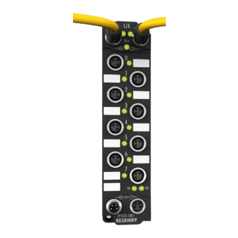
EtherCAT Box - Introduction EtherCAT Box - Introduction The EtherCAT system has been extended with EtherCAT Box modules with protection class IP67. Through the integrated EtherCAT interface the modules can be connected directly to an EtherCAT network without an additional Coupler Box. The high-performance of EtherCAT is thus maintained into each module. The extremely low dimensions of only 126 x 30 x 26.5 mm (h x w x d) are identical to those of the Fieldbus Box extension modules. - Page 12 Fig. 3: EtherCAT Box with M12 connections for sensors/actuators Basic EtherCAT documentation You will find a detailed description of the EtherCAT system in the Basic System Documentation for EtherCAT, which is available for download from our website (www.beckhoff.com) under Downloads. Version: 2.10 EP5xxx...
-
Page 13: Product Overview
Product overview Product overview Module overview SSI encoder interface Module Connection Number Sensor Comment encoder/sensor supply chan- nels M12 socket, 8-pin 24 V Distributed Clocks EP5001-0002 [} 14] Incremental encoder interface with differential inputs Module Connection Number Sensor Comment encoder/sensor supply chan- nels M12 socket, 8-pin 5 V... -
Page 14: Ep5001-0002 - Introduction
Product overview EP5001-0002 3.2.1 EP5001-0002 - Introduction SSI encoder interface The EP5001-0002 EtherCAT box is an SSI master and enables the direct connection of an absolute encoder with SSI (synchronous serial interface). Both singleturn and multiturn encoders are supported. An 8-pin M12 socket is used as encoder connection. -
Page 15: Ep5001-0002 - Technical Data
Product overview 3.2.2 EP5001-0002 - Technical data All values are typical values over the entire temperature range, unless stated otherwise. EtherCAT Connection 2 x M8 socket, 4-pin, A-coded, shielded Electrical isolation 500 V Distributed Clocks Supply voltages Connection Input: M8 connector, 4-pin, A-coded Downstream connection: M8 socket, 4-pin, A-coded nominal voltage 24 V... -
Page 16: Ep5001-0002 - Scope Of Supply
Product overview *) Real applicable approvals/markings see type plate on the side (product marking). Additional tests The devices have undergone the following additional tests: Test Explanation Vibration 10 frequency sweeps in 3 axes 5 Hz < f < 60 Hz displacement 0.35 mm, constant amplitude 60.1 Hz < f < 500 Hz acceleration 5 g, constant amplitude Shocks 1000 shocks in each direction, in 3 axes 35 g, 11 ms... -
Page 17: Ep5001-0002 - Process Image
Product overview 3.2.4 EP5001-0002 - Process image TwinCAT displays the process image in a tree structure. TwinCAT shows the data of the EP5001-0002 in a tree structure. SSI Inputs Status • Data error SSI input error • Frame error Wrong data frame •... -
Page 18: Ep5101-X002
Product overview EP5101-x002 3.3.1 EP5101-x002 - Introduction Incremental encoder interface with differential inputs The EP5101-x002 EtherCAT Box is an interface for the direct connection of incremental encoders with differential signals (RS422) or TTL single ended signals. Input frequencies up to 1 MHz can be evaluated. The C input can optionally be used as a latch input. -
Page 19: Ep5101-X002 - Technical Data
Product overview 3.3.2 EP5101-x002 - Technical data All values are typical values over the entire temperature range, unless stated otherwise. EtherCAT Connection 2 x M8 socket, 4-pin, A-coded, shielded Electrical isolation 500 V Distributed Clocks Supply voltages Connection Input: M8 connector, 4-pin, A-coded Downstream connection: M8 socket, 4-pin, A-coded nominal voltage 24 V... -
Page 20: Ep5101-X002 - Scope Of Supply
Product overview Approvals/markings EP5101-0002 EP5101-1002 Approvals/markings ATEX, CE, cURus [} 42], CE, cURus [} 42], EAC, EAC, UKCA UKCA Additional tests The devices have undergone the following additional tests: Test Explanation Vibration 10 frequency sweeps in 3 axes 5 Hz < f < 60 Hz displacement 0.35 mm, constant amplitude 60.1 Hz < f < 500 Hz acceleration 5 g, constant amplitude Shocks 1000 shocks in each direction, in 3 axes... -
Page 21: Ep5101-X002 - Process Image
Product overview 3.3.4 EP5101-x002 - Process image TwinCAT shows the data of the EP5101-0002 and EP5101-1002 in a tree structure, using the EP5101-0002 as an example. ENC Status Compact Input data of the encoder interface Status • Latch C valid New data are available in the process data Latch value. -
Page 22: Ep5101-X011
Product overview EP5101-x011 3.4.1 EP5101-x011 - Introduction Incremental encoder interface with differential inputs The EP5101-x011 EtherCAT Box is an interface for the direct connection of incremental encoders with differential signals (RS422) or TTL single ended signals. Two additional 24 V digital inputs are available for storing, locking and setting the counter reading. -
Page 23: Ep5101-X011 - Technical Data
Product overview 3.4.2 EP5101-x011 - Technical data All values are typical values over the entire temperature range, unless stated otherwise. EtherCAT Connection 2 x M8 socket, 4-pin, A-coded, shielded Electrical isolation 500 V Distributed Clocks Supply voltages Connection Input: M8 connector, 4-pin, A-coded Downstream connection: M8 socket, 4-pin, A-coded nominal voltage 24 V... -
Page 24: Ep5101-X011 - Scope Of Supply
Product overview Approvals/markings Approvals/markings CE, cURus [} 42] *) Real applicable approvals/markings see type plate on the side (product marking). Additional tests The devices have undergone the following additional tests: Test Explanation Vibration 10 frequency sweeps in 3 axes 5 Hz < f < 60 Hz displacement 0.35 mm, constant amplitude 60.1 Hz < f < 500 Hz acceleration 5 g, constant amplitude Shocks 1000 shocks in each direction, in 3 axes... -
Page 25: Ep5101-0011 - Process Image
Product overview 3.4.4 EP5101-0011 - Process image TwinCAT shows the data of the EP5101-0011 in a tree structure. ENC Status Compact Status • Latch C valid New data are available in the process data Latch value. Reset via Enable latch C •... -
Page 26: Ep5101-2011 - Process Image
Product overview 3.4.5 EP5101-2011 - Process image TwinCAT shows the data of the EP5101-2011 in a tree structure. ENC Status Compact Status • Latch C valid New data are available in the process data Latch value. Reset via Enable latch C •... -
Page 27: Ep5151-0002 - Introduction
Product overview EP5151-0002 3.5.1 EP5151-0002 – Introduction 1-channel encoder interface, incremental, 24 V HTL, 100 kHz, M12 The EP5151-0002 EtherCAT Box module is an interface for direct connection of 24 V DC single-ended signals. Two additional 24 V digital inputs are available for saving, locking, and setting the counter value. The alarm output of an encoder can be connected and evaluated via the status input. -
Page 28: Ep5151-0002 - Technical Data
Product overview 3.5.2 EP5151-0002 - Technical data All values are typical values over the entire temperature range, unless stated otherwise. EtherCAT Connection 2 x M8 socket, 4-pin, A-coded, shielded Electrical isolation 500 V Distributed Clocks Supply voltages Connection Input: M8 connector, 4-pin, A-coded Downstream connection: M8 socket, 4-pin, A-coded nominal voltage 24 V... -
Page 29: Ep5151-0002 - Scope Of Supply
Product overview Additional tests The devices have undergone the following additional tests: Test Explanation Vibration 10 frequency sweeps in 3 axes 5 Hz < f < 60 Hz displacement 0.35 mm, constant amplitude 60.1 Hz < f < 500 Hz acceleration 5 g, constant amplitude Shocks 1000 shocks in each direction, in 3 axes 35 g, 11 ms 3.5.3 EP5151-0002 - Scope of supply... -
Page 30: Ep5151-0002 - Process Image
Product overview 3.5.4 EP5151-0002 - Process image ENC Status Compact Status • Latch C valid New data are available in the process data Latch value. Reset via Enable latch C • Latch extern valid New data are available in the process data Latch value. -
Page 31: Mounting And Connection
Mounting and connection Mounting and connection Mounting 4.1.1 Dimensions 26.5 13.5 Ø 3.5 All dimensions are given in millimeters. The drawing is not true to scale. Housing features Housing material PA6 (polyamide) Sealing compound polyurethane Mounting two mounting holes Ø 3.5 mm for M3 Metal parts brass, nickel-plated Contacts... -
Page 32: Fixing
Mount the module with two M3 screws on the mounting holes in the corners of the module. The mounting holes have no thread. 4.1.3 Tightening torques for plug connectors Screw M8 connectors tight with a torque wrench. (e.g. ZB8801 from Beckhoff) Torque: 0.4 Nm. Version: 2.10 EP5xxx... -
Page 33: Ethercat
Mounting and connection EtherCAT 4.2.1 Connectors NOTICE Risk of confusion: supply voltages and EtherCAT Defect possible through incorrect insertion. • Observe the color coding of the connectors: black: Supply voltages green: EtherCAT EtherCAT Box Modules have two green M8 sockets for the incoming and downstream EtherCAT connections. -
Page 34: Status Leds
(CAT5) according to EN 50173 or ISO/IEC 11801 should be used. EtherCAT uses four wires for signal transmission. Thanks to automatic line detection ("Auto MDI-X"), both symmetrical (1:1) or cross-over cables can be used between Beckhoff EtherCAT. Detailed recommendations for the cabling of EtherCAT devices Version: 2.10... -
Page 35: Supply Voltages
Mounting and connection Supply voltages WARNING Power supply from SELV/PELV power supply unit! SELV/PELV circuits (Safety Extra Low Voltage, Protective Extra Low Voltage) according to IEC 61010-2-201 must be used to supply this device. Notes: • SELV/PELV circuits may give rise to further requirements from standards such as IEC 60204-1 et al, for example with regard to cable spacing and insulation. -
Page 36: Connectors
Control voltage Brown Peripheral voltage White GND to U Blue GND to U Black The core colors apply to cables of the type: Beckhoff ZK2020-3xxx-xxxx 4.3.2 Status LEDs Display Meaning (control voltage) The supply voltage U is not available. green illuminated The supply voltage U is available. -
Page 37: Conductor Losses
Mounting and connection 4.3.3 Conductor losses Take into account the voltage drop on the supply line when planning a system. Avoid the voltage drop being so high that the supply voltage at the box lies below the minimum nominal voltage. Variations in the voltage of the power supply unit must also be taken into account. -
Page 38: Signal Connection And Meaning Of The Leds
Mounting and connection Signal connection and meaning of the LEDs 4.4.1 Shielding Shielding Encoder, analog sensors and actuators should always be connected with shielded, twisted paired wires. 4.4.2 EP5001-0002 - Signal connection LED indicators - meanings green Data Encoder supply switched on (operational SSI without power supply state, not short-circuited) Open circuit on the SSI data input D+ or D-... -
Page 39: Ep5101-X002 - Signal Connection
Mounting and connection 4.4.3 EP5101-x002 - Signal connection Encoder pin assignment, M12, socket, 8-pin LED indicators - meanings Connection LED Display Meaning Input A / track A low green Input A / track A high Input B / track B low green Input B / track B high Input C / track C low... -
Page 40: Ep5101-X011 - Signal Connection
Mounting and connection 4.4.4 EP5101-x011 - Signal connection Encoder pin assignment, D-sub socket, 15-pin LED indicators - meanings Connection Display Meaning D sub Input A / track A low green Input A / track A high Input B / track B low green Input B / track B high Input C / track C low... -
Page 41: Ep5151-0002 - Signal Connection
Mounting and connection 4.4.5 EP5151-0002 - Signal connection Encoder connection, M12 socket, 8-pin LED indicators - meanings Connection LED Display Meaning Input A / track A low green Input A / track A high Input B / track B low green Input B / track B high Input C / track C low... -
Page 42: Ul Requirements
Mounting and connection UL Requirements The installation of the EtherCAT Box Modules certified by UL has to meet the following requirements. Supply voltage CAUTION CAUTION! This UL requirements are valid for all supply voltages of all marked EtherCAT Box Modules! For the compliance of the UL requirements the EtherCAT Box Modules should only be supplied •... -
Page 43: Atex Notes
Mounting and connection ATEX notes 4.6.1 ATEX - Special conditions WARNING Observe the special conditions for the intended use of EtherCAT Box modules in potentially explosive areas – directive 94/9/EU. • The certified components are to be installed with a BG2000-0000 or BG2000-0010 protection enclosure [} 44] that guarantees a protection against mechanical hazards! •... -
Page 44: Bg2000 - Ethercat Box Protection Enclosures
Mounting and connection 4.6.2 BG2000 - EtherCAT Box protection enclosures WARNING Risk of electric shock and damage of device! Bring the EtherCAT system into a safe, powered down state before starting installation, disassembly or wiring of the modules! ATEX WARNING Mount a protection enclosure! To fulfill the special conditions according to ATEX [} 43], a BG2000-0000 or BG2000-0010 protection enclosure has to be mounted over the EtherCAT Box. -
Page 45: Atex Documentation
Notes about operation of EtherCAT Box Modules (EPxxxx-xxxx) in potentially explosive areas (ATEX) Pay also attention to the continuative documentationNotes about operation of EtherCAT Box Modules (EPxxxx-xxxx) in potentially explosive areas (ATEX) that is available in the download area of the Beckhoff homepage http:\\www.beckhoff.com! EP5xxx Version: 2.10... -
Page 46: Disposal
Mounting and connection Disposal Products marked with a crossed-out wheeled bin shall not be discarded with the normal waste stream. The device is considered as waste electrical and electronic equipment. The national regulations for the disposal of waste electrical and electronic equipment must be observed. Version: 2.10 EP5xxx... -
Page 47: Commissioning/Configuration
Commissioning/Configuration Commissioning/Configuration Integrating into a TwinCAT project The procedure for integration in a TwinCAT project is described in this Quick start guide. EP5xxx Version: 2.10... -
Page 48: Ep5001-0002 - Parameters And Modes
Commissioning/Configuration EP5001-0002 - Parameters and modes 5.2.1 Basic principles of SSI communication SSI principles SSI communication sequence • The SSI master starts pulsing on the clock line with a fixed cycle into the shift register of the SSI slave. • The slave generally "pushes back" data with a width of 25 bits on the data line. An SSI encoder should determine its position with the first falling edge of the signal at the Clock input ("latching"), which is then transferred. -
Page 49: Process Data
Commissioning/Configuration 5.2.2 Process data The EP5001-0002 can have 16 bit status data and a 32-bit counter value. Fig. 10: EP5001-0002 EP5xxx Version: 2.10... - Page 50 Commissioning/Configuration 5.2.2.1 EP5001-0002 - PDO assignment Fig. 11: PDO assignment and content; example: EP5001-0002 The PDO 0x1A00 configuration of the EP5001-0002 cannot be changed. PDO Assignment SM3, PDO Assignment 0x1C13 Index Index of excluded Size Name PDO Content PDOs (byte.bit) (index - name) 0x1A00 SSI Inputs 0x6000:01 [} 81] - Data error...
-
Page 51: Dc (Distributed Clocks)
Commissioning/Configuration 5.2.3 DC (Distributed Clocks) Describes whether the module is operated with support from distributed clocks: Fig. 12: Distributed Clocks • FreeRun: The module operates frame-triggered. Cyclic operation is started via the SyncManagers during EtherCAT frame processing. • DC-Synchron: Cyclic operation in the module is started by the local distributed clock at exact intervals. The start time is chosen such that it coincides with other output slaves in the EtherCAT system. -
Page 52: Features Coe
Commissioning/Configuration 5.2.4 Features CoE Further settings can be selected in the CoE (CAN over EtherCAT)-list. Parameterization via the CoE list (CAN over EtherCAT) Please note the following general CoE notes when using/manipulating the CoE parameters: • Keep a startup list if components have to be replaced •... - Page 53 Commissioning/Configuration Specification of the encoder Settings in the CoE of the box Error bit 0x8000:0F SSI 0x8000:11 SSI 0x8000:12 SSI data 0x8000:02 Enable power failure frame type frame size length 1: Single-turn 0: Power failure bit is not active analysis is active 0: Multi-turn 1: Power failure bit is active analysis is active...
-
Page 54: Ep51X1-X0Xx - Parameters And Modes
Commissioning/Configuration EP51x1-x0xx - Parameters and modes 5.3.1 Basic function principles The box acquires the 90° phase-shifted digital output signal of an incremental encoder on channels A and B. The zero pulse is acquired on channel C. These signals are converted into a position value with quadruple evaluation with the aid of the quadrature encoder and the 32-bit counter. -
Page 55: Process Data
Commissioning/Configuration 5.3.2 Process data 16 or 32 bit process data The Box can be operated with 16 bit process data (default) or 32 bit process data. This can be set via the Predefined PDO Assignment in the Process Data table tab. Fig. 14: 16 or 32 bit process data EP5xxx Version: 2.10... - Page 56 Commissioning/Configuration Main PDO Selection of basic process data Fig. 15: Main PDO example A: Selection of data direction: input or output C: Explanatory notes for PDOs B: Selection of (optional) PDOs (process data D: PDO content objects) • compact: The process data can be represented with 16 bits (compact) or with 32 bits. Optional PDOs Optional PDOs, in addition to the main PDO: •...
- Page 57 Commissioning/Configuration 5.3.2.1 EP5101-x002 - PDO assignment PDO Assignment To configure the process data, select the required Sync Manager (SM 2 or SM 3 can be changed) in the Sync Manager field at the top left (see illustration above). The process data assigned to this Sync Manager can then be switched on or off in the PDO Assignment field below.
- Page 58 Commissioning/Configuration SM3, PDO Assignment 0x1C13 Index Index of excluded Size Name PDO Content PDOs (byte.bit) (index - name) 0x1A00 0x1A01 ENC Status compact 0x6000:01 [} 85] - Latch C valid (default) 0x6000:03 [} 85] - Set counter done 0x6000:04 [} 85] - Counter underflow 0x6000:05 [} 85] - Counter overflow 0x6000:07 [} 85] - Open circuit 0x6000:08 [} 85] - Extrapolation stall...
- Page 59 Commissioning/Configuration SM3, PDO Assignment 0x1C13 Index Index of excluded Size Name PDO Content PDOs (byte.bit) (index - name) 0x1A00 0x1A01 ENC Status 0x6000:01 [} 113] - Latch C valid (default) compact 0x6000:02 [} 113] - Latch extern valid 0x6000:03 [} 113] - Set counter done 0x6000:04 [} 113] - Counter underflow 0x6000:05 [} 113] - Counter overflow 0x6000:06 [} 113] - Status of input status...
- Page 60 Commissioning/Configuration 5.3.2.2 EP5101-0011 - PDO assignment PDO Assignment To configure the process data, select the required Sync Manager (SM 2 or SM 3 can be changed) in the Sync Manager field at the top left (see illustration above). The process data assigned to this Sync Manager can then be switched on or off in the PDO Assignment field below.
- Page 61 Commissioning/Configuration SM2, PDO Assignment 0x1C12 Index Index of excluded Size Name PDO Content PDOs (byte.bit) (index - name) 0x1600 0x1601 ENC Control 0x7000:01 [} 101] - Enable Latch C (default) compact 0x7000:02 [} 101] - Enable Latch extern on positive edge 0x7000:03 [} 101] - Set counter 0x7000:04 [} 101] - Enable Latch extern on negative edge 0x7000:11 [} 101] - Set counter value (16-bit) 0x1601...
- Page 62 Commissioning/Configuration 5.3.2.3 EP5101-2011 - PDO assignment Fig. 16: PDO assignment and content, EP5101-2011 PDO Assignment To configure the process data, select the required Sync Manager (SM 2 or SM 3 can be changed) in the Sync Manager field at the top left (see illustration above). The process data assigned to this Sync Manager can then be switched on or off in the PDO Assignment field below.
- Page 63 Commissioning/Configuration SM2, PDO Assignment 0x1C12 Index Index of excluded Size Name PDO Content PDOs (byte.bit) (index - name) 0x1600 0x1601 ENC Control 0x7000:01 - Enable Latch C 0x7000:02 - Enable Latch extern on positive edge 0x7000:03 - Set counter 0x7000:04 - Enable Latch extern on negative edge 0x7000:11 - Set counter value (32-bit) 0x1601 0x1600...
- Page 64 Commissioning/Configuration 5.3.2.4 EP5151-0002 - PDO assignment PDO Assignment To configure the process data, select the required Sync Manager (SM 2 or SM 3 can be changed) in the Sync Manager field at the top left (see illustration above). The process data assigned to this Sync Manager can then be switched on or off in the PDO Assignment field below.
- Page 65 Commissioning/Configuration SM2, PDO Assignment 0x1C12 Index Index of excluded Size Name PDO Content PDOs (byte.bit) (index - name) 0x1600 0x1601 ENC Control 0x7000:01 [} 114] - Enable Latch C (default) compact 0x7000:02 [} 114] - Enable Latch extern on positive edge 0x7000:03 [} 114] - Set counter 0x7000:04 [} 114] - Enable Latch extern on negative edge 0x7000:11 [} 114] - Set counter value (16-bit) 0x1601...
-
Page 66: Dc (Distributed Clocks)
Commissioning/Configuration 5.3.3 DC (Distributed Clocks) Describes whether the module is operated with support from distributed clocks: Fig. 17: Distributed Clocks • FreeRun: The module operates frame-triggered. Cyclic operation is started via the SyncManagers during EtherCAT frame processing. • DC-Synchron: Cyclic operation in the module is started by the local distributed clock at exact intervals. The start time is chosen such that it coincides with other output slaves in the EtherCAT system. -
Page 67: Features Coe
Commissioning/Configuration 5.3.4 Features CoE Depending on the main PDO/optional PDOs further settings can be selected in the CoE list (CAN over EtherCAT). Parameterization via the CoE list (CAN over EtherCAT) Please note the following general CoE notes when using/manipulating the CoE parameters: •... - Page 68 Commissioning/Configuration Additional Notes Frequency • The time window for the frequency calculation and the resolution can be parameterized in the CoE objects Frequency window 0x8000:11, Frequency scaling 0x8000:13, Frequency resolution 0x8000:15 and Frequency wait time 0x8000:17. • The positive edges of track A are counted within the specified timeframe and the next edge including the time up to it are counted.
- Page 69 Commissioning/Configuration Latch • Activation of latch C input (Enable latch C index 0x7000:01) and saving ("latching") of the counter value ◦ The counter value is saved when the first external latch pulse (positive edge at input "C") is encountered after the bit has been set (TRUE) in Enable latch C index 0x7000:01 (this has priority over Enable latch extern on positive / negative edge 0x7000:02 / 0x7000:04).
- Page 70 Commissioning/Configuration Overflow/underflow (not for product version -2011) • Overflow/underflow control is inactive in combination with an activated reset function (C/external). • The underflow bit (0x6000:04) is set if an underflow ...00 ->...FF occurs. It is reset if 2/3 of the counter range are underrun.
- Page 71 Commissioning/Configuration Fig. 20: DC-supported micro-increments The highly constant query cycles (accuracy: 100 ns) of the distributed clocks systems enable the Box to interpolate axis positions between the counted encoder increments from a certain speed. The interpolation resolution is 8 bit, corresponding to 256 values. A standard encoder with 1,024 lines with 4-way evaluation and micro-increments thus becomes a high-resolution axis encoder with 4096 x 256 = 1,048,567 lines.
-
Page 72: Ep5001 - Interface Signal Level
Commissioning/Configuration EP5001 - Interface signal level The SSI interface works with differential signal levels conforms to RS422 / RS485. The “typical output level” applies for a load of 60 ohm or higher. Single-ended signal levels are not supported. Version: 2.10 EP5xxx... -
Page 73: Ep5101 - Interface Signal Level
Commissioning/Configuration EP5101 - Interface signal level In differential mode the encoder input expects signal levels conforms to RS422 / RS485. The data are transferred without ground reference as voltage difference between two cables (signal A and inverted signal / A). The encoder input analyses differences greater than 200 mV as valid signals. The differential signal must be in the common mode range (<+13.2 V and >-10 V, with respect to GND) (cf. -
Page 74: Ep5151 - Interface Signal Level
Commissioning/Configuration EP5151 - Interface signal level The encoder input expects level after HTL (push-pull). Version: 2.10 EP5xxx... -
Page 75: Restore The Delivery State
Commissioning/Configuration Restore the delivery state You can restore the delivery state of the backup objects as follows: 1. Ensure that TwinCAT is running in Config mode. 2. In CoE object 1011:0 "Restore default parameters" select parameter 1011:01 "Subindex 001". 3. Double-click on "Subindex 001". ð... -
Page 76: Decommissioning
Commissioning/Configuration Decommissioning WARNING Risk of electric shock! Bring the bus system into a safe, de-energized state before starting disassembly of the devices! Version: 2.10 EP5xxx... -
Page 77: Coe Parameters
You can parameterize the box via the "CoE - Online" tab in TwinCAT. EtherCAT XML Device Description The presentation matches that of the EtherCAT XML Device Description. Recommendation: download the latest XML file from https://www.beckhoff.com/ and install it according to the installation instructions. Introduction The CoE overview contains objects for different intended applications: •... - Page 78 CoE parameters Index 1018 Identity Index (hex) Name Meaning Data type Flags Default 1018:0 Identity Information for identifying the slave UINT8 0x04 (4 1018:01 Vendor ID Vendor ID of the EtherCAT slave UINT32 0x00000002 1018:02 Product code Product code of the EtherCAT slave UINT32 0x13894052 (327762002...
- Page 79 CoE parameters Index 1C12 RxPDO assign Index (hex) Name Meaning Data type Flags Default 1C12:0 RxPDO assign PDO Assign Outputs UINT8 0x00 (0 Index 1C13 TxPDO assign Index (hex) Name Meaning Data type Flags Default 1C13:0 TxPDO assign PDO Assign Inputs UINT8 0x02 (2 1C13:01...
- Page 80 CoE parameters Index 1C33 SM input parameter Index (hex) Name Meaning Data type Flags Default 1C33:0 SM input parameter Synchronization parameters for the inputs UINT8 0x20 (32 1C33:01 Sync mode Current synchronization mode: UINT16 0x0022 (34 • 0: Free Run •...
- Page 81 CoE parameters Index 6000 SSI Inputs Index (hex) Name Meaning Data type Flags Default 6000:0 SSI Inputs Length of this object UINT8 0x11 (17 6000:01 Data error SSI input error: BOOLEAN 0x00 (0 - SSI without power supply - Broken wire at SSI data inputs D+ or D- - Data cables interchanged If no data transmission occurs, the SSI input is on low signal level.
- Page 82 CoE parameters Index 800D SSI Advanced Settings Index (hex) Name Meaning Data type Flags Default 800D:0 SSI advanced SSI advanced settings 0x03 (3 settings 800D:01 Encoder power Switches the 24 V supply voltage 0x01 (1 supply on 800D:02 Encoder direction Switches the 24 V supply at the direction pin 0x00 (0 pin on 800D:03...
-
Page 83: Ep5101-X002
You can parameterize the box via the "CoE - Online" tab in TwinCAT. EtherCAT XML Device Description The presentation matches that of the EtherCAT XML Device Description. Recommendation: download the latest XML file from https://www.beckhoff.com/ and install it according to the installation instructions. 6.2.1... -
Page 84: Configuration Data
CoE parameters 6.2.2 Configuration data Index 8000 ENC Settings Index (hex) Name Meaning Data type Flags Default 8000:0 ENC Settings Maximum subindex UINT8 0x17 (23 8000:01 Enable C reset [} 69] The counter is reset via the C input. BOOLEAN 0x00 (0 8000:03 Enablement of the up/down counter in place of the encoder BOOLEAN... -
Page 85: Input Data
CoE parameters Index (hex) Name Meaning Data type Flags Default 8000:17 Waiting time [ms] for frequency measurement UINT16 0x0640 Frequency wait time Once the time specified in the frequency window has (1600 [} 68] elapsed, the system waits for the next positive edge from track A. -
Page 86: Output Data
CoE parameters 6.2.4 Output data Index 7000 ENC Outputs Index (hex) Name Meaning Data type Flags Default 7000:0 ENC Outputs Maximum subindex UINT8 0x11(17 7000:01 Enable latch C [} 69] Activate latching via input “C”. BOOLEAN 0x00 (0 7000:03 Set counter Set counter value BOOLEAN 0x00 (0... - Page 87 CoE parameters Index 10F0 Backup parameter handling Index (hex) Name Meaning Data type Flags Default 10F0:0 Backup parameter Information for standardized loading and saving of backup UINT8 0x01 (1 handling entries 10F0:01 Checksum Checksum across all backup entries of the EtherCAT slave UINT32 0x00000000 Index 1400 ENC RxPDO-Par Control compact Index (hex) Name...
- Page 88 CoE parameters Index 1601 ENC RxPDO Map Control (product version -0002) Index (hex) Name Meaning Data type Flags Default 1601:0 ENC RxPDO-Map PDO Mapping RxPDO UINT8 0x06 (6 Control compact 1601:01 SubIndex 001 1. PDO Mapping entry (object 0x7000 (ENC Outputs), UINT32 0x7000:01,1 entry 0x01 (Enable latch C))
- Page 89 CoE parameters Index 1803 ENC TxPDO-Par Period Index (hex) Name Meaning Data type Flags Default 1803:0 ENC TxPDO-Par PDO parameter TxPDO 4 UINT8 0x06 (6 Period 1803:06 Exclude TxPDOs Specifies the TxPDOs (index of TxPDO mapping objects) OCTET- 02 1A that must not be transferred together with TxPDO 4.
- Page 90 CoE parameters Index 1A00 ENC TxPDO Map Status compact (product version -1002) Index (hex) Name Meaning Data type Flags Default 1A00:0 ENC TxPDO-Map ENC TxPDO-Map Status compact UINT8 0x012 (18 Status compact 1A00:01 SubIndex 001 1. PDO Mapping entry (object 0x6000 (ENC Inputs), entry UINT32 0x6000:01, 1 0x01 (Latch C valid))
- Page 91 CoE parameters Index 1A01 ENC TxPDO Map Status (product version -0002) Index (hex) Name Meaning Data type Flags Default 1A01:0 ENC TxPDO-Map ENC TxPDO-Map Status UINT8 0x11 (17 Status compact 1A01:01 SubIndex 001 1. PDO Mapping entry (object 0x6000 (ENC Inputs), entry UINT32 0x6000:01, 1 0x01 (Latch C valid))
- Page 92 CoE parameters Index 1A01 ENC TxPDO Map Status (product version -1002) Index (hex) Name Meaning Data type Flags Default 1A01:0 ENC TxPDO-Map ENC TxPDO-Map Status UINT8 0x12 (18 Status compact 1A01:01 SubIndex 001 1. PDO Mapping entry (object 0x6000 (ENC Inputs), entry UINT32 0x6000:01, 1 0x01 (Latch C valid))
- Page 93 CoE parameters Index 1A05 ENC TxPDO-Map Timest. compact Index (hex) Name Meaning Data type Flags Default 1A05:0 ENC TxPDO-Map ENC TxPDO-Map Timest. compact UINT8 0x01 (1 Timest. compact 1A05:01 SubIndex 001 1. PDO Mapping entry (object 0x6000 (ENC Inputs), entry UINT32 0x6000:16, 32 0x16 (Timestamp))
- Page 94 CoE parameters Index 1C32 SM output parameter Index (hex) Name Meaning Data type Flags Default 1C32:0 SM output Synchronization parameters for the outputs UINT8 0x20 (32 parameter 1C32:01 Sync mode Current synchronization mode: UINT16 0x0001 (1 • 0: Free Run •...
- Page 95 CoE parameters Index 1C33 SM input parameter Index (hex) Name Meaning Data type Flags Default 1C33:0 SM input parameter Synchronization parameters for the inputs UINT8 0x20 (32 1C33:01 Sync mode Current synchronization mode: UINT16 0x0022 (34 • 0: Free Run •...
- Page 96 CoE parameters Index F010 Module list Index (hex) Name Meaning Data type Flags Default F010:0 Module list Maximum subindex UINT8 0x02 (2 F010:01 SubIndex 001 reserved UINT32 0x000001FE (510 Version: 2.10 EP5xxx...
- Page 97 You can parameterize the box via the "CoE - Online" tab in TwinCAT. EtherCAT XML Device Description The presentation matches that of the EtherCAT XML Device Description. Recommendation: download the latest XML file from https://www.beckhoff.com/ and install it according to the installation instructions. 6.3.1...
- Page 98 CoE parameters 6.3.2 Configuration data Index 8000 ENC Settings Index (hex) Name Meaning Data type Flags Default 8000:0 ENC Settings Maximum subindex UINT8 0x17 (23 8000:01 Enable C reset [} 69] The counter is reset via the C input. BOOLEAN 0x00 (0 8000:02 A counter reset is triggered via the external latch input BOOLEAN...
- Page 99 CoE parameters Index (hex) Name Meaning Data type Flags Default 8000:16 Internal resolution of the period value measurement: 100: UINT16 0x0064 (100 Period resolution “100 ns” period value is a multiple of 100 ns [} 68] The period is calculated internally with a resolution of 100 ns.
- Page 100 CoE parameters 6.3.3 Input data Index 6000 ENC Inputs Index (hex) Name Meaning Data type Flags Default 6000:0 ENC Inputs Maximum subindex UINT8 0x16 (22 6000:01 The counter value was latched with the “C” input. The data BOOLEAN 0x00 (0 Latch C valid [} 69] with Latch Value (Index 0x6000:12) corresponds to the latched value if the bit is set.
- Page 101 CoE parameters 6.3.4 Output data Index 7000 ENC Outputs Index (hex) Name Meaning Data type Flags Default 7000:0 ENC Outputs Maximum subindex UINT8 0x11(17 7000:01 Enable latch C [} 69] Activate latching via input “C”. BOOLEAN 0x00 (0 7000:01 Activate external latch with positive edge. BOOLEAN 0x00 (0 Enable latch extern...
- Page 102 CoE parameters Index 1018 Identity Index (hex) Name Meaning Data type Flags Default 1018:0 Identity Information for identifying the slave UINT8 0x04 (4 1018:01 Vendor ID Vendor ID of the EtherCAT slave UINT32 0x00000002 1018:02 Product code Product code of the EtherCAT slave UINT32 0x13ED4052 (334315602...
- Page 103 CoE parameters Index 1601 ENC RxPDO-Map Control Index (hex) Name Meaning Data type Flags Default 1601:0 ENC RxPDO-Map PDO Mapping RxPDO UINT8 0x07 (7 Control compact 1601:01 SubIndex 001 1. PDO Mapping entry (object 0x7000 (ENC Outputs), UINT32 0x7000:01,1 entry 0x01 (Enable latch C)) 1601:02 SubIndex 002 2.
- Page 104 CoE parameters Index 1805 ENC TxPDO-Par Timest. compact Index (hex) Name Meaning Data type Flags Default 1805:0 ENC TxPDO-Par PDO parameter TxPDO 6 UINT8 0x06 (6 Timest. compact 1805:06 Exclude TxPDOs Specifies the TxPDOs (index of TxPDO mapping objects) OCTET- 04 1A that must not be transferred together with TxPDO 6 STRING[2]...
- Page 105 CoE parameters Index 1A01 ENC TxPDO-Map Status Index (hex) Name Meaning Data type Flags Default 1A01:0 ENC TxPDO-Map PDO Mapping TxPDO 2 UINT8 0x12 (18 Status compact 1A01:01 SubIndex 001 1. PDO Mapping entry (object 0x6000 (ENC Inputs), entry UINT32 0x6000:01, 1 0x01 (Latch C valid)) 1A01:02...
- Page 106 CoE parameters Index 1A05 ENC TxPDO-Map Timest. compact Index (hex) Name Meaning Data type Flags Default 1A05:0 ENC TxPDO-Map PDO Mapping TxPDO UINT8 0x01 (1 Timest. compact 1A05:01 SubIndex 001 1. PDO Mapping entry (object 0x6010 (ENC Inputs), UINT32 0x6000:16, 32 entry 0x16 (Timestamp)) Index 1C00 Sync manager type Index (hex) Name...
- Page 107 CoE parameters Index 1C32 SM output parameter Index (hex) Name Meaning Data type Flags Default 1C32:0 SM output parameter Synchronization parameters for the outputs UINT8 0x20 (32 1C32:01 Sync mode Current synchronization mode: UINT16 0x0001 (1 • 0: Free Run •...
- Page 108 CoE parameters Index 1C33 SM input parameter Index (hex) Name Meaning Data type Flags Default 1C33:0 SM input parameter Synchronization parameters for the inputs UINT8 0x20 (32 1C33:01 Sync mode Current synchronization mode: UINT16 0x0022 (34 • 0: Free Run •...
- Page 109 CoE parameters Index F010 Module list Index (hex) Name Meaning Data type Flags Default F010:0 Module list Maximum subindex UINT8 0x02 (2 F010:01 SubIndex 001 reserved UINT32 0x000001FE (510 F010:02 SubIndex 002 reserved UINT32 0x000001FF (511 EP5xxx Version: 2.10...
- Page 110 You can parameterize the box via the "CoE - Online" tab in TwinCAT. EtherCAT XML Device Description The presentation matches that of the EtherCAT XML Device Description. Recommendation: download the latest XML file from https://www.beckhoff.com/ and install it according to the installation instructions. 6.4.1...
- Page 111 CoE parameters 6.4.2 Configuration data Index 8000 ENC Settings Index (hex) Name Meaning Data type Flags Default 8000:0 ENC Settings Maximum subindex UINT8 0x17 (23 8000:01 Enable C reset [} 69] The counter is reset via the C input. BOOLEAN 0x00 (0 8000:02 A counter reset is triggered via the external latch input BOOLEAN...
- Page 112 CoE parameters Index (hex) Name Meaning Data type Flags Default 8000:16 Internal resolution of the period value measurement: 100: UINT16 0x0064 (100 Period resolution “100 ns” period value is a multiple of 100 ns [} 68] The period is calculated internally with a resolution of 100 ns.
- Page 113 CoE parameters 6.4.3 Input data Index 6000 ENC Inputs Index (hex) Name Meaning Data type Flags Default 6000:0 ENC Inputs Maximum subindex UINT8 0x16 (22 6000:01 The counter value was latched with the “C” input. The data BOOLEAN 0x00 (0 Latch C valid [} 69] with Latch Value (Index 0x6000:12) corresponds to the latched value if the bit is set.
- Page 114 CoE parameters 6.4.4 Output data Index 7000 ENC Outputs Index (hex) Name Meaning Data type Flags Default 7000:0 ENC Outputs Maximum subindex UINT8 0x11(17 7000:01 Enable latch C [} 69] Activate latching via input “C”. BOOLEAN 0x00 (0 7000:01 Activate external latch with positive edge. BOOLEAN 0x00 (0 Enable latch extern...
- Page 115 CoE parameters Index 10F0 Backup parameter handling Index (hex) Name Meaning Data type Flags Default 10F0:0 Backup parameter Information for standardized loading and saving of backup UINT8 0x01 (1 handling entries 10F0:01 Checksum Checksum across all backup entries of the EtherCAT slave UINT32 0x00000000 Index 1400 ENC RxPDO-Par Control compact Index (hex) Name...
- Page 116 CoE parameters Index 1800 ENC TxPDO-Par Status compact Index (hex) Name Meaning Data type Flags Default 1800:0 ENC TxPDO-Par PDO parameter TxPDO 1 UINT8 0x09 (9 Status compact 1800:06 Exclude TxPDOs Specifies the TxPDOs (index of TxPDO mapping objects) OCTET- 01 1A that must not be transferred together with TxPDO 1.
- Page 117 CoE parameters Index 1A00 ENC TxPDO-Map Status compact Index (hex) Name Meaning Data type Flags Default 1A00:0 ENC TxPDO-Map ENC TxPDO-Map Status compact UINT8 0x012 (18 Status 1A00:01 SubIndex 001 1. PDO Mapping entry (object 0x6000 (ENC Inputs), entry UINT32 0x6000:01, 1 0x01 (Latch C valid)) 1A00:02...
- Page 118 CoE parameters Index 1A01 ENC TxPDO-Map Status Index (hex) Name Meaning Data type Flags Default 1A01:0 ENC TxPDO-Map PDO Mapping TxPDO 2 UINT8 0x12 (17 Status compact 1A01:01 SubIndex 001 1. PDO Mapping entry (object 0x6000 (ENC Inputs), entry UINT32 0x6000:01, 1 0x01 (Latch C valid)) 1A01:02...
- Page 119 CoE parameters Index 1A05 ENC TxPDO-Map Timest. compact Index (hex) Name Meaning Data type Flags Default 1A05:0 ENC TxPDO-Map PDO Mapping TxPDO UINT8 0x01 (1 Timest. compact 1A05:01 SubIndex 001 1. PDO Mapping entry (object 0x6000 (ENC Inputs), entry UINT32 0x6000:16, 32 0x16 (Timestamp)) Index 1C00 Sync manager type...
- Page 120 CoE parameters Index 1C32 SM output parameter Index (hex) Name Meaning Data type Flags Default 1C32:0 SM output Synchronization parameters for the outputs UINT8 0x20 (32 parameter 1C32:01 Sync mode Current synchronization mode: UINT16 0x0001 (1 • 0: Free Run •...
- Page 121 CoE parameters Index 1C33 SM input parameter Index (hex) Name Meaning Data type Flags Default 1C33:0 SM input parameter Synchronization parameters for the inputs UINT8 0x20 (32 1C33:01 Sync mode Current synchronization mode: UINT16 0x0022 (34 • 0: Free Run •...
- Page 122 CoE parameters Index F010 Module list Index (hex) Name Meaning Data type Flags Default F010:0 Module list Maximum subindex UINT8 0x01 (1 F010:01 SubIndex 001 reserved UINT32 0x000001FF (511 Version: 2.10 EP5xxx...
-
Page 123: Appendix
Appendix Appendix General operating conditions Protection rating according to IP code The degrees of protection are defined and divided into different classes in the IEC 60529 standard (EN 60529). Degrees of protection are designated by the letters "IP" and two numerals: IPxy •... -
Page 124: Accessories
Torque cable key for M12 / wrench size 13 for ZB8801-0000 ZB8801-0003 Torque cable key for M12 field assembly / wrench size 18 for ZB8801-0000 Further accessories Further accessories can be found in the price list for fieldbus components from Beckhoff and online at https://www.beckhoff.com. Version: 2.10 EP5xxx... -
Page 125: Version Identification Of Ethercat Devices
Associated and synonymous with each revision there is usually a description (ESI, EtherCAT Slave Information) in the form of an XML file, which is available for download from the Beckhoff web site. From 2014/01 the revision is shown on the outside of the IP20 terminals, see Fig. “EL5021 EL terminal, standard IP20 IO device with batch number and revision ID (since 2014/01)”. -
Page 126: Version Identification Of Ip67 Modules
Version identification of IP67 modules The serial number/ data code for Beckhoff IO devices is usually the 8-digit number printed on the device or on a sticker. The serial number indicates the configuration in delivery state and therefore refers to a whole production batch, without distinguishing the individual modules of a batch. -
Page 127: Beckhoff Identification Code (Bic)
7.3.3 Beckhoff Identification Code (BIC) The Beckhoff Identification Code (BIC) is increasingly being applied to Beckhoff products to uniquely identify the product. The BIC is represented as a Data Matrix Code (DMC, code scheme ECC200), the content is based on the ANSI standard MH10.8.2-2016. - Page 128 Fig. 23: Example DMC 1P072222SBTNk4p562d71KEL1809 Q1 51S678294 An important component of the BIC is the Beckhoff Traceability Number (BTN, position 2). The BTN is a unique serial number consisting of eight characters that will replace all other serial number systems at Beckhoff in the long term (e.g.
-
Page 129: Electronic Access To The Bic (Ebic)
Electronic access to the BIC (eBIC) Electronic BIC (eBIC) The Beckhoff Identification Code (BIC) is applied to the outside of Beckhoff products in a visible place. If possible, it should also be electronically readable. The interface that the product can be electronically addressed by is crucial for the electronic readout. - Page 130 • The following auxiliary functions are available for processing the BIC/BTN data in the PLC in Tc2_Utilities as of TwinCAT 3.1 build 4024.24 ◦ F_SplitBIC: The function splits the Beckhoff Identification Code (BIC) sBICValue into its components using known identifiers and returns the recognized substrings in the ST_SplittedBIC structure as a return value ◦...
-
Page 131: Support And Service
Please contact your Beckhoff branch office or representative for local support and service on Beckhoff products! The addresses of Beckhoff's branch offices and representatives round the world can be found on her internet pages: www.beckhoff.com You will also find further documentation for Beckhoff components there. - Page 133 Beckhoff Automation GmbH & Co. KG Hülshorstweg 20 33415 Verl Germany Phone: +49 5246 9630 info@beckhoff.com www.beckhoff.com...
Need help?
Do you have a question about the EP5 Series and is the answer not in the manual?
Questions and answers