Table of Contents
Advertisement
Advertisement
Table of Contents

Related Manuals for Husqvarna LP 9505


Summary of Contents for Husqvarna LP 9505
- Page 1 LP 9505 Operator's manual 2-49...
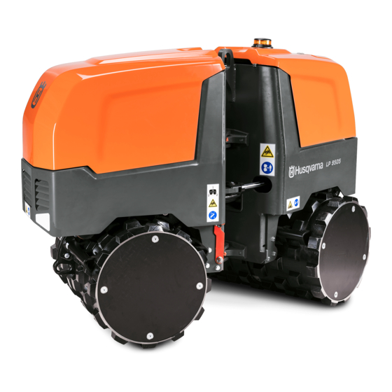
- Page 2 Contents Introduction..............2 Transportation, storage and disposal......41 Safety................14 Technical data.............. 44 Operation..............19 EC Declaration of Conformity........48 Maintenance..............30 Supplier's declaration of Conformity......49 Introduction California Proposition 65 Product description The product is a trench compactor with articulation WARNING! joints.
- Page 3 Product overview Product overview, fuel filters on Product overview, rear hatch on 1. Fuel filters. Refer to 7. Rear hatch. Refer to page 4 . page 6 . 2. Front machine distance sensor (MDS) 8. Warning light 3. Front cover 9.
- Page 4 Product overview, fuel filters 1. Fuel filter 3. Fuel prefilter 2. Drain plug for the water separator 1423 - 002 - 03.04.2020...
- Page 5 Product overview, front parts 1. Radiator coolant cap 6. Loudspeaker 2. Radiator coolant tank 7. Air filter 3. Sight glass for radiator coolant level 8. Vacuator valve 4. Engine oil cap 9. Muffler 5. Oil dipstick 10. Engine oil filter 1423 - 002 - 03.04.2020...
- Page 6 Product overview, rear hatch Product overview, remote 1. Remote control. Refer to 4. Fuse box control on page 8 and Symbols on the remote 5. 12 V power socket control on page 12 . 6. Battery switch Symbols on the electrical 2.
- Page 7 Product overview, rear parts 1. Sight glass for hydraulic oil level 7. Fuel tank 2. Antenna 8. Buzzer 3. Cover for the hydraulic oil filter 9. Starter battery Product overview, receiver on 4. Hydraulic oil tank 10. Receiver. Refer to page 9 .
- Page 8 Product overview, remote control 1. Button to make selections in the menus 10. Emergency stop button 2. ON/OFF button 11. Switch for high/low amplitude for vibration 3. Display 12. Switch for manual/automatic vibration 4. Indicator for front machine distance sensor 13.
- Page 9 Product overview, receiver STATUS LED FSK12 CABLE PAIRING 1. Antenna 5. Connector for cable remote control 2. Status indicator 6. Connector for CAN bus cable 3. "RX" indicator 7. Connector for power 4. Pairing operation button 1423 - 002 - 03.04.2020...
- Page 10 Product overview, fuses Symbols on the product 1. F1: 7.5 A, electronic control unit 2. F2: 7.5 A, electronic control unit WARNING: This product can be dangerous 3. F3: 7.5 A, electronic control unit and cause serious injury or death to the 4.
- Page 11 Tie-down bracket. Use protective boots. Engage the articulation joint lock before you lift the product. Engage the articulation joint lock when you attach the product to a transportation vehicle. Maximum slope angle. The product is remote control operated. Always be careful and use your common Do not spray with water.
- Page 12 Keep a minimum of 10 m/33 ft distance to persons and animals during operation of the 33ft product. Do not use high pressure washer. Note: Other symbols/decals on the product refer to special certification requirements for some markets. Keep distance to the product during operation.
- Page 13 1. Serial number 2. Bar code Battery switch OFF. Start instruction decal Type plate The start instruction decal on the product shows the start procedure. Husqvarna AB 561 82 Huskvarna Sweden Made in Bulgaria Type Operating mass kg Rated power kW Art.No.
- Page 14 Lift and tie-down decal Product liability This decal shows how to lift and safety the product. As referred to in the product liability laws, we are not liable for damages that our product causes if: • the product is incorrectly repaired. •...
- Page 15 • Make sure that only approved persons are in the • If an error occurs in the control system, push the work area. emergency stop button on the remote control and disconnect the battery. Let an approved service • Keep the work area clean and bright. center repair the product.
- Page 16 Work area safety • Do not breathe the exhaust fumes. • Make sure that the airflow in the work area is • During operation, no one is permitted to be in the sufficient. This is very important when you operate area (A) shown in the illustration.
- Page 17 Do a check of the safety devices regularly. If the safety devices are defective, speak to your To do a check of the vibration damping units Husqvarna service agent. There are 12 vibration damping units, 6 on the left side and 6 on the right side of the product.
- Page 18 • All tanks are full. has a deformation or is damaged, speak to • The surface is hard. an approved Husqvarna service agent. • The maximum slope angle is 20° (36%) in these conditions: • The product is stationary with its side in direction WARNING: Read the warning instructions of the slope.
- Page 19 Safety instructions for operation near edges • Clean the product to remove dangerous material before you do the maintenance. • Disconnect the spark plug cap before you do the maintenance. WARNING: Read the warning instructions that follow before you use the product. •...
- Page 20 "RX" indicator on the receiver 1. Pull out the locking pin (A). The "RX" indicator on the receiver shows the state of connection to the remote control. LED indicator Cause Flashes green quickly. The remote control is not connected to the receiver. Flashes green slowly.
- Page 21 Remote control battery 3. Put the battery into the battery slot and close the battery hatch. 2 Li-Ion batteries are supplied with the product. The second battery can be charged in the battery charger on the product during operation or in the optional desktop charger.
- Page 22 1. Open the rear hatch on the product and remove the 6. Push and hold 1 of the joysticks (C or D) on the remote control. remote control away from center position. 2. Turn the battery switch to "1". 7. Push the ON/OFF button (E) on the remote control to start the remote control.
- Page 23 To connect the remote control to the product 5. Tighten the connector screw for the CAN bus cable by hand. with a CAN bus cable LED indicators on the remote control When a CAN bus cable is used, the remote control battery is not necessary.
- Page 24 Indi- Cause indi- cation Alarm. The hydraulic oil temperature is too cator high. The engine stops. Off. The remote control is not connected to the receiver. Flash- The remote control is connected to Alarm. The hydraulic oil level is too low. The the receiver.
- Page 25 Pairing operation indica- Messages on the display tions Information. It is necessary to do servicing on the product. The pairing operation is "Pairing mode" not correctly done. "***Pairing***" Information. The remote control is connected to the product with the CAN bus "BT ERROR"...
- Page 26 2. Open the rear hatch on the product and remove the 5. Push the ON/OFF button (A) on the remote control remote control. to start the remote control. A PIN code can be necessary to start the remote control. Refer to codes on page 21 .
- Page 27 To operate the product 1. Push the switch for engine speed (A) up to set the highest engine speed. WARNING: Make sure that you can see the product at all times when you operate the product. The operation range of the remote control makes it possible to move the product also when you cannot see it.
- Page 28 1. Push the switch for engine speed (A) up to set the 2. Set the vibration switch (A) to the "0" position. highest engine speed. 2. Push the switch for operation speed (B) down to set low operation speed. 3. Push the switch for high/low amplitude (C) to the "0" position.
- Page 29 10. Push the ON/OFF button (E) on the remote control. 4. Remove the air filter hose (A). The indicator for main contactor (F) goes off. 11. Put the remote control behind the rear hatch on the product. 12. Close the rear hatch and lock the rear hatch with a padlock.
- Page 30 Maintenance Introduction X = The instructions are given in this operator's manual. O = Refer to the instructions in the engine manual WARNING: Read and understand the safety supplied by the engine manufacturer. chapter before you do maintenance on the product.
- Page 31 General product maintenance Before After Each Each Each Each Each Each use, 50 h 250 h 500 h 1000 h 1500 h 3000 h each first 50 10 h Do a check of the fan belt tension. Do a check of the radiator coolant hoses and the clamps.
- Page 32 To clean the fuel tank 5. Open the fuel tank cap (F). 1. Release the lock (A) to for the fuel tank strap (B). 6. Drain the fuel tank. 7. Use a fuel filter hook to pull out the fuel hose (G) and 2.
- Page 33 2. Pull out the oil dipstick (A). 2. Remove the oil drain plug. 3. Clean the oil from the oil dipstick. 3. Let the engine oil run out into the container. 4. Put the oil dipstick back in. 4. Install the oil drain plug and tighten it. Make sure that there is no leakage.
- Page 34 To do a check of the radiator coolant 6. Clean the surfaces (A) carefully. level 1. Park the product on level ground and stop the To stop the product on page 28 . engine. Refer to 2. Examine the sight glass for radiator coolant level (A). The radiator coolant level is correct when it is in the middle of the sight glass.
- Page 35 2. Remove the drain plug for the radiator coolant. 1. Loosen the clamps and remove the air filter cover (B) with the vacuator valve (A). 3. Let the radiator coolant water drain into the container. 4. Install the drain plug for the radiator coolant and tighten it.
- Page 36 To do a check of the scrapers 7. Clean the surface of the air filter seal and the inner side of the filter housing with a clean cloth. 1. Make sure that the scraper blades (A) do not touch 8. Install the air filter in the opposite sequence. the drums.
- Page 37 To do a check of the fan belt tension 4. Push the fan belt (E) between the pulleys. The tension is correct if the fan belt moves between 7-9 1. Find the fan guards (A) and the alternator cover (B). mm/0.28-0.35 in.
- Page 38 c) Pull out the alternator until the fan belt can move 4. Remove the oil fill plug for the eccentric element (B). between 7-9 mm/0.28-0.35 in. d) Tighten the alternator bolts. 7. Install the alternator cover and tighten the 2 screws. 8.
- Page 39 Technical 8. Fill the eccentric element with oil. Refer to 1. Remove the fuel filter (A) with a wrench. data on page 44 for correct quantity and type of oil. 9. Install the oil fill plug for the eccentric element. 10.
- Page 40 1. Put a container below the drain plug for the hydraulic trickle charging when the battery is fully charged. oil. The container must have a capacity minimum of Speak to your Husqvarna dealer for information 15 l/4 gal. about the correct battery charger.
- Page 41 2. Remove the drain plug for the hydraulic oil. 7. Examine the hydraulic oil level at the sight glass for the hydraulic oil tank (B). The hydraulic oil level is correct when it is 10 mm/0.39 in. from the top of the sight glass.
- Page 42 • Make sure that the load area on the transportation 1. Make sure that the vibration damping units (A) are To do vehicle and wheels on the product is clean. correctly installed and not damaged. Refer to a check of the vibration damping units on page 17 . •...
- Page 43 Obey the local recycling requirements and applicable regulations. • Do not discard the battery as domestic waste. • Send the battery to a Husqvarna service agent or discard it at a disposal location for used batteries. 1423 - 002 - 03.04.2020...
- Page 44 Technical data Technical data Net weight, kg/lb 1660/3660 Operation weight (EN500), kg/lb 1675/3693 Engine type Kubota D1105, 3-cylinder Diesel Engine power, kW/hp @rpm 18/24.1 @2800 Cooling system Combined water/hydraulic oil cooler and fan Air filter Dry type Pump traction system Gear type Engines traction system Radial Piston...
- Page 45 Eccentric element, l/qt 0.8/0.84 Water tank, l/gal 58/12.75 Fuel consumption, l/h or qt/h 3.5 or 3.7 Engine oil * Shell Rimula R4 L 15W-40 Eccentric element oil Shell Omala S4 GX 150 Hydraulic oil Shell Tellus S2 V 46 Fuel * Only use ultra-low-sulfur diesel fuel (0.0015% or 15 p.p.m) that complies with EN 560 or DIN 51601 CAUTION: Do not use bio-diesel.
- Page 46 Storage temperature without battery, °C/°F Between -40/-40 and 85/185 Charge temperature for battery, °C/°F Between 10/50 and 45/113 Receiver Operating voltage, V DC 12/24, negative grounded system General consumption 100 mA, without external charging at 12 V DC Processor 2 CPU design, 2 solid state safety switches (RCSS). De- signed to fulfill ISO 13849-1, Cat3, Pl d.
- Page 47 Product dimensions Distance between product Width, mm/in. 589/23 529/21 and ground, mm/in. Drum width inner, mm/in. 630/25 Drum radius, mm/in. 226/10 Drum width outer, mm/in. 850/33 Drum diameter, mm/in. 573/23 Distance between front and Length, mm/in. 1856/73 990/39 rear drum axles, mm/in. Distance between front and Height without warning light 1330/52...
- Page 48 EC Declaration of Conformity EC Declaration of Conformity We, Husqvarna AB, SE-561 82 Huskvarna, Sweden, tel: +46-36-146500, declare on our sole responsibility that the product: Description Articulated Trench Compactor Brand Husqvarna Type/Model LP 9505 Identification Serial numbers dating from 2019 and onwards...
- Page 49 U.S. Contact Information: Neil Stanford, Compliance Manager, Telephone number: 913-928-1000 FCC Compliance Statement: Changes or modifications not expressly approved by Husqvarna can void the equipment’s compliance with FCC regulations, and limit the user's authority to operate the equipment. Compliance requirements...
- Page 50 1423 - 002 - 03.04.2020...
- Page 51 1423 - 002 - 03.04.2020...
- Page 52 www.husqvarnacp.com Original instructions 1141125-26 2020-04-15...
Need help?
Do you have a question about the LP 9505 and is the answer not in the manual?
Questions and answers