Table of Contents
Advertisement
Quick Links
Advertisement
Table of Contents

Subscribe to Our Youtube Channel
Related Manuals for CTC Union ICR-W401


Summary of Contents for CTC Union ICR-W401
- Page 1 ICR-W401 Industrial 4G LTE Router...
- Page 2 CTC Union Technologies makes no warranty, representation, or guarantee regarding the suitability of its products for any particular purpose, nor does CTC Union assume any liability arising out of the application or use of any product and specifically disclaims any and all liability, including without limitation any consequential or incidental damages.
- Page 3 This document is the current official release manual. Contents are subject to change without prior notice. Please check CTC Union's website for any updated manual or contact us by E-mail at sales@ctcu.com. Please address any comments for improving this manual or to point out omissions or errors to marketing@ctcu.com.
-
Page 4: Table Of Contents
TABLE OF CONTENTS Table of Contents Introduction ........................7 1.1 Features..........................7 1.2 Specifications ........................8 1.3 Mechanical Dimensions ..................... 9 1.4 Hardware Panel Layout ...................... 9 Hardware Installation ...................... 11 2.1 LED Indicators ......................... 11 2.2 Ethernet Port ........................11 2.3 Grounding the Router....................... - Page 5 TABLE OF CONTENTS 3.5.1 LTE > LTE Config ..................... 45 3.5.1.1 LTE Configuration ..............................45 3.5.2 LTE > GPS Config ....................46 3.5.3 LTE > GPS Track ..................... 47 3.5.4 LTE > APN Config ....................48 3.5.5 LTE > APN1 Usage ....................51 3.5.6 LTE >...
- Page 6 TABLE OF CONTENTS 3.10.7 NAT ........................123 3.10.8 IPS ........................123 3.11 Service ......................... 124 3.11.1 SNMP ........................124 3.11.1.1 SNMP configuration ............................124 3.11.1.2 SNMP v3 User configuration ........................... 125 3.11.1.3 SNMP trap configuration ..........................126 3.11.2 TR069 ........................127 3.11.3 Dynamic DNS .......................
-
Page 7: Introduction
9.6-60VDC, ICR-W401 are ideal devices to be applied in diverse environments for various applications. ICR-W401 Industrial 4G LTE Cellular Routers are suitable and reliable choices for fast deployment and easy configuration to simplify your complicated solutions and fit your services for industrial networking and smart city. -
Page 8: Specifications
CHAPTER 1. INTRODUCTION 1.2 Specifications Cellular Interface Software Standards: Network Protocols: ▪ IPv4, IPv6, IPv4/IPv6 dual stack, DHCP server and (Please see ordering information for optional band) client, ▪ 4G: FDD LTE, TDD LTE ▪ PPPoE, Static IP, SNTP, GPS sync time, DNS Proxy ▪... -
Page 9: Mechanical Dimensions
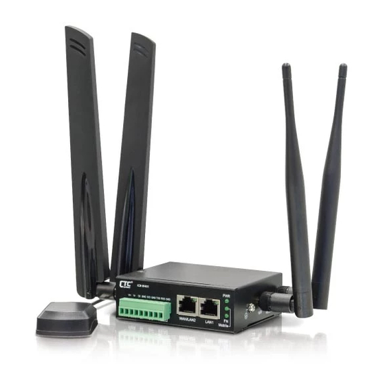
CHAPTER 1. INTRODUCTION 1.3 Mechanical Dimensions 1.4 Hardware Panel Layout This chapter describes the panel and interface layout of hardware. Front Panel View Left Side Panel View Right Side Panel View... - Page 10 CHAPTER 1. INTRODUCTION Index No. Description Fast Ethernet RJ-45 LAN port Fast Ethernet RJ-45 WAN or LAN port Terminal block for PWR, DI, DO, RS232 LED indicators (PWR, Mobile, FN) Micro SIM card slot Mobile MAIN connector Mobile AUX connector GPS connector Earth grounding WPS/Reset push button...
-
Page 11: Hardware Installation
CHAPTER 2. HARDWARE INSTALLATION 2 Hardware Installation This chapter introduces how to install and connect the hardware. 2.1 LED Indicators Color Status Meaning The system is receiving power and up. Green The system is down. High signals. Slow Blinking Medium signals or reset Mobile Green Fast Blinking... -
Page 12: Grounding The Router
CHAPTER 2. HARDWARE INSTALLATION (2) LED Indicator of Ethernet Port Each Ethernet port has one LED indicators. The Green LED indicates Link/ACT. Status Description Connection is down. Green (Link/ACT) Blink Data is being transmitted. Connection is up. 2.3 Grounding the Router To prevent the noise and surge effect, please connect the router to the site ground wire by the ground screw before turning on the router. -
Page 13: Connecting The Power Supply
CHAPTER 2. HARDWARE INSTALLATION 2.5 Connecting the Power Supply The router requires a DC power supply (12/24/48VDC) in the range of 9.6~60VDC. Please ensure all components are earthed to a common ground before connecting any wiring. Power (9.6~60VDC) Negative Positive 2.6 Connecting I/O Ports (1) Digital Input (DI) The unit has two terminals on the terminal block for the Digital inputs. -
Page 14: Uart (Rs-232)
CHAPTER 2. HARDWARE INSTALLATION 2.7 UART (RS-232) The port is a standard RS-232 signal level interface. Signal Direction Transmit Data Output Receive Data Input Signal Ground... -
Page 15: Install The Sim Card
CHAPTER 2. HARDWARE INSTALLATION 2.8 Install the SIM Card Insert and Remove SIM Card (1) Before inserting or removing the SIM card, ensure that the power has been turned off and the power connector has been removed from Cellular Router. (2) Insert the SIM card with right direction. -
Page 16: External Antennas
Each unit has three kinds of antenna connectors, these are, MAIN, GPS, AUX (SMA). For ICR-W401, there are five antenna connectors, two for LTE antennas, two for Wi-Fi (RP-SMA) antennas and one for GPS antenna. Connect the antenna to MAIN when you have only one LTE... -
Page 17: Configuration Via Web Browser
CHAPTER 3. WEB CONFIGURATIONS 3 Configuration via Web Browser 3.1 Access the Web Interface The web configuration is an HTML-based management interface for quick and easy set up of the Mobile Router. Monitoring of the status, configuration and administration of the router can be done via the Web interface. -
Page 18: Navigate The Web Configurator
CHAPTER 3. WEB CONFIGURATIONS Enter the new Super User password and retype the password to confirm. Then, click Apply button. The system needs a reboot to take new password into effect. Note: After changing the User Name and Password, we strongly recommend that you save them because another time when you login, new User Name and Password have to be used so as to successfully login to the system. - Page 19 CHAPTER 3. WEB CONFIGURATIONS A : Title Bar The title bar provides some useful instructions that show the status of the router. Title Bar Item Description Show if the SIM card is inserted in the slot. If yes, RSSI (Received Signal RSSI shows the current signal strength in a wireless network and Strength Indicator)
-
Page 20: Status
CHAPTER 3. WEB CONFIGURATIONS 3.2 Status When you enter the web configurator and have not logged in, the first item of main menu shows your status as a guest. This status only allows you to view status page without any permission to log in. - Page 21 CHAPTER 3. WEB CONFIGURATIONS Status > GPS Item Description Attribute Latitude Show the latitude information of location. Longitude Show the longitude information of location. Horizontal Show the horizontal information of location. Altitude Show the altitude information of location. Date (UTC) Show the date information of location.
- Page 22 CHAPTER 3. WEB CONFIGURATIONS Status > WAN LTE Item Description Attribute (Attr.) Modem Status The status of LTE. Operator Display the name of operator. Modem Access The router to access protocol type. IMSI The IMSI number of the SIM card. Phone Number The phone number of the SIM card.
- Page 23 CHAPTER 3. WEB CONFIGURATIONS Status > WAN Ethernet Item Description Attribute IPv4 Address Ethernet WAN obtain IPv4 Address. IPv4 Mask Ethernet WAN obtain IPv4 Mask. Default Gateway Ethernet WAN IPv4 Default Gateway. IPv6 Conn Time Ethernet WAN IPv4 Connected Time. Status >...
-
Page 24: Status > Gps
CHAPTER 3. WEB CONFIGURATIONS 3.2.1 Status > GPS For those GPS enabled routers, you can see Location on the upper-right banner of web interface when connecting your GPS function. After clicking Google Maps banner, the current information of map according to location of router will be automatically displayed. -
Page 25: System
CHAPTER 3. WEB CONFIGURATIONS 3.3 System This system section provides you to configure the following items, including Time and Date, Logging, Alarm, Ethernet Ports, and Client List. 3.3.1 System > Time and Date This section allows you to set up the time and date of router and NTP server. There are two modes at Time and Date Setup, including Get from Time Server and Manual. - Page 26 CHAPTER 3. WEB CONFIGURATIONS II. Manual Set up the information of time and date, including year, month, date, and hour, minute, and second. Set up your local time zone. Click Apply to submit your configuration changes.
- Page 27 CHAPTER 3. WEB CONFIGURATIONS III. Time Zone Setup Set up Daylight Savings as On. Set up Ahead of standard time. Set up the information of Start Date/Time, including Month, Week, Day, Hour and Minute. Set up the information of End Date/Time, including Month, Week, Day, Hour and Minute.
- Page 28 CHAPTER 3. WEB CONFIGURATIONS System > Time Zone Setup > Daylight Savings Item Description Turn on/off the Daylight Savings feature. Select from Off or On. Daylight Saving The default is Off. The forward/backward minutes when enter/leave Daylight Ahead of standard time Savings duration.
-
Page 29: System > Com
CHAPTER 3. WEB CONFIGURATIONS IV. Time Server The Time server feature allows user to set a time server for LAN side client to get the time through NTP/SNTP protocol. System > Time Server Item Description Server mode Turn on/off the time server. Server port The UDP port listened by time server. -
Page 30: System > Logging
CHAPTER 3. WEB CONFIGURATIONS System > COM Item Description Baud Rate Select the baud rate Data Select the data bit. Parity Select the parity value. Stop Select the stop value. Flow Control Select the flow control options. 3.3.3 System > Logging This section allows cellular router to record the data and display the status of data. -
Page 31: Logging > Log
CHAPTER 3. WEB CONFIGURATIONS 3.3.3.2 Logging > Log This section displays all data status. (1) You can choose Filter function to quickly search for your data. (2) When you click Clear, all of the data that displays on the interface will be totally cleared without any backup. -
Page 32: System > Alarm
CHAPTER 3. WEB CONFIGURATIONS 3.3.4 System > Alarm This section allows you to configure the alarm. Note: (1) If you select SMS in Alarm input/output, you need to add the trust phone number into Contracts/ On Duty. (2) If you select SNMP trap in Alarm output, you need to set up SNMP trap configuration from Service SNMP. -
Page 33: Alarm > Contacts > Create And Name The Group
CHAPTER 3. WEB CONFIGURATIONS as alarm output. Select from High or Low. The default is High Trigger. High: SW is On to trigger. Trigger Low: SW is OFF to trigger. Always: Pull DO high. DO behavior Pulse: High and Low continuously. ... - Page 34 CHAPTER 3. WEB CONFIGURATIONS You can click button to edit or delete the group. ...
-
Page 35: Alarm > Contacts > Add User
CHAPTER 3. WEB CONFIGURATIONS 3.3.4.2 Alarm > Contacts > Add User Select your naming group and click + Add User button to add your user’s information, including Name, Phone and E-mail. After filling in your information for each row, chose your naming group and click ... -
Page 36: Alarm > Duty Schedule
CHAPTER 3. WEB CONFIGURATIONS button to edit the user’s information or click the check box and You can click to delete the user. 3.3.4.3 Alarm > Duty Schedule Select Duty Schedule to edit the schedule of the on duty group. ... - Page 37 CHAPTER 3. WEB CONFIGURATIONS System > Ethernet Ports Item Description Ethernet Ports Status Show the connectivity status of LAN and WAN. Select from Auto, 100M Full, 100M Half, 10M Full, 10M Ethernet Ports Configurations Half and Disable. MTU is the Maximum Transmission Unit that can be sent WAN Ethernet over the WAN Ethernet interface.
-
Page 38: System > Client List
CHAPTER 3. WEB CONFIGURATIONS 3.3.6 System > Client List This section allows you to understand how many devices have been connected and their status from the router. There are two types, one is DHCP Client and the other is Online. The default is both types to show all status when the router is on DHCP Client and Online. -
Page 39: Wan
CHAPTER 3. WEB CONFIGURATIONS 3.4 WAN This section allows you to configure WAN, including Priority, Ethernet and IPv6 DNS. 3.4.1 WAN > Priority You can set up the priority of WAN. The default is Auto. WAN > Priority Item Description Auto (ETH ->... -
Page 40: Wan > Ethernet
CHAPTER 3. WEB CONFIGURATIONS 3.4.2 WAN > Ethernet 3.4.2.1 WAN Ethernet Configuration This section provides three options, including DHCP Client, PPPoE Client and Static IPv4. The default is DHCP Client. WAN > Ethernet Item Description There are three options to obtain the IP of WAN Ethernet. DHCP Client: DHCP server-assigned IP address, netmask, gateway, ... - Page 41 CHAPTER 3. WEB CONFIGURATIONS WAN > Ethernet > DHCP Client Item Description Each setting DNS Server has three options, including From ISP, User Defined and None. IPv4 DNS Server #1 When you select From ISP, the IPv4 DNS server IP is obtained ...
- Page 42 CHAPTER 3. WEB CONFIGURATIONS WAN > Ethernet > Static IPv4 Item Description Static IPv4 Configuration IP Address Fill in the IP Address. IP Mask Fill in the IP Mask. Gateway Address Fill in Gateway Address. DNS Server Configuration IPv4 DNS Server #1 IPv4 DNS Server #2 The IPv4 DNS server IP is input by user.
-
Page 43: Wan > Ipv6 Dns
CHAPTER 3. WEB CONFIGURATIONS 3.4.3 WAN > IPv6 DNS This section allows you to set up IPv6 DNS Server Configuration. For IPv6 DNS Server, it provides three entries to set up and each entry has provided with “From ISP”, “User Defined” and “None” to configure. WAN >... -
Page 44: Wan > Health Check
CHAPTER 3. WEB CONFIGURATIONS 3.4.4 WAN > Health Check If you configure “WAN Priority” to “Auto” mode, the system would choose the cost-effective connection first such as Ethernet. However, in case the Ethernet connection exists but it is unable to access internet; you can enable “Health Check” and the system would switch to LTE connection and switch back whenever Ethernet is able to access internet again. -
Page 45: Lte
CHAPTER 3. WEB CONFIGURATIONS 3.5 LTE This section allows you to configure LTE Config, GPS Config, Dual APN, APN Usage, SMS, Serving Cell, and DNS. 3.5.1 LTE > LTE Config 3.5.1.1 LTE Configuration You can set up the LTE Configuration and LTE Ping Health. LTE >... -
Page 46: Lte > Gps Config
CHAPTER 3. WEB CONFIGURATIONS 3.5.2 LTE > GPS Config This section allows you to set up GPS Configuration and connect RS232 from the used router to have more detailed information for your specific purpose. You can download software from internet and activate the GPS Configuration to display what information you need from your software. -
Page 47: Lte > Gps Track
CHAPTER 3. WEB CONFIGURATIONS LTE > GPS Config Item Description Report to Select from TCP Server and LOG. TCP Server Interval Specify the interval value for reporting to the TCP server. IPv4 Address Specify the IPv4 address of the TCP server. IPv4 Address Port Specify the port number of the TCP server. -
Page 48: Lte > Apn Config
CHAPTER 3. WEB CONFIGURATIONS 3.5.4 LTE > APN Config This section allows you to understand the status of connectivity for APN. SIM PIN: If you have configured SIM PIN code into SIM card, please type SIM PIN code in Dual SIM configuration to make unlock successfully. - Page 49 CHAPTER 3. WEB CONFIGURATIONS Change SIM PIN:If you want to change SIM PIN code, you can click Change button and type old SIM PIN code and new SIM PIN code. Please aware not to exceed the retry number (PIN remaining number and PUN remaining number).
- Page 50 CHAPTER 3. WEB CONFIGURATIONS PIN remaining number Display the allowed remaining PIN retry number. PUK remaining number Display the allowed remaining PUK retry number. APN1 The Access Point Name (APN) is the name of the setting that set up a connection to the gateway between your carrier's cellular network and the public Internet.
-
Page 51: Lte > Apn1 Usage
CHAPTER 3. WEB CONFIGURATIONS 3.5.5 LTE > APN1 Usage This section shows the status of current SIM card, operator, IMSI and the charts for Real Time, Hourly, Daily, Weekly, and Monthly. Real-Time Usage: It displays accumulated real-time Download/Upload/Total MB for 10 seconds period. - Page 52 CHAPTER 3. WEB CONFIGURATIONS (1) Hourly Usage: It displays Download/Upload/Total MB per hour in one day for current using SIM card and the view window size is 24 hours.
- Page 53 CHAPTER 3. WEB CONFIGURATIONS (2) Daily Usage: It displays Download/Upload/Total MB per day in one month for current using SIM card and the view window size is 31 days.
- Page 54 CHAPTER 3. WEB CONFIGURATIONS (3) Weekly Usage: It displays Download/Upload/Total MB per day in one week for current using SIM card and the view window size is 7 days.
-
Page 55: Lte > Sms
CHAPTER 3. WEB CONFIGURATIONS (4) Monthly Usage: It displays Download/Upload/Total MB per month in one year for current using SIM card and the view window size is 12 months. 3.5.6 LTE > SMS This section provides two settings, one is SMS Action and the other is View SMS. (1) When enabling SMS Action, it only allows trust phone number which listed in Contacts/On Dutyt by sending key words SMS to trigger device setting/action/query status. - Page 56 CHAPTER 3. WEB CONFIGURATIONS (2) View SMS allows you to review the information of SMS that you have received, including the state, phone and date and time. You can click view button to review all messages, button to clear all messages, and button to reload all messages.
-
Page 57: Lte > Serving Cell
CHAPTER 3. WEB CONFIGURATIONS 3.5.7 LTE > Serving Cell This section displays all parameters, including the following items:... -
Page 58: Lte > Dns
CHAPTER 3. WEB CONFIGURATIONS LTE > Serving Cell Item Description RSRP Reference Signal Received Power. RSRQ Reference Signal Received Quality. SINR Loarithmic value of SINR. RSCP The Received Signal Code Power Level of the cell that was scanned. ECIO Carrier to noise ratio in dB = measured Ec/lo value in dB. Cell Identity eNB ID (20 Bits) + Cell ID (8 Bits). -
Page 59: Lte > Ussd
CHAPTER 3. WEB CONFIGURATIONS 3.5.9 LTE > USSD USSD stands for "Unstructured Supplementary Service Code" which also refers to "quick codes" or "feature codes". USSD is a protocol used by GSM mobile service to communicate mobile with computers of service providers based on the predefined set of codes and messages. Users can use USSD to create sessions so as to exchange data or communicate for a period of time as long as the connection remains open. -
Page 60: Wifi
CHAPTER 3. WEB CONFIGURATIONS 3.6 WiFi This section allows you to set up the WiFi configuration. 3.6.1 WiFi > WiFi Config This section allows you to set up the Wi-Fi configuration. WiFi > Config Item Description Turn on/off the Wi-Fi Network. Select from Disable or Enable. The AP Enable default is Enable. -
Page 61: Wifi > Mac Filter
CHAPTER 3. WEB CONFIGURATIONS WiFi > Config Item Description malicious users in distant area will not be able to access the signals.) AP isolation is a technique for preventing mobile devices connected AP Isolate to an AP from communicating directly with each other. 20M: Only 20MHz Operation is Supported,40M: Both 20MHz and HT Mode (HT Capability) 40MHz Operation is Supported. -
Page 62: Wifi > Client List
CHAPTER 3. WEB CONFIGURATIONS WiFi > MAC Filter Item Description Mode Select from Disable. The default is Disable. MAC Address Fill in your MAC address. 3.6.3 WiFi > Client List This section allows you to see all the Connected WiFi Client List. Item Description MAC Address... -
Page 63: Lan
CHAPTER 3. WEB CONFIGURATIONS 3.7 LAN This section allows you to configure LAN IPv4, LAN IPv6, VLAN and Subnet. 3.7.1 LAN > IPv4 Set up your IP Address and IP Mask. Also, fill in the information of DHCP Server Configuration. LAN >... -
Page 64: Lan > Ipv6
CHAPTER 3. WEB CONFIGURATIONS 3.7.2 LAN > IPv6 Select your type of IPv6, which shows Delegate Prefix from WAN or Static, and then set up DHCP Server Configuration, including Address Assign, DNS Assign and DNS Server. LAN > IPv6 Item Description Delegate Prefix from WAN ... - Page 65 CHAPTER 3. WEB CONFIGURATIONS When VLAN Mode is set to Tag Base, the VLAN setting window will appear as below. The VLAN Isolation function allows administrator to separate the different Subnet (VLAN). When it is on, the different Subnet (VLAN) user cannot communication each other. For each row, the settings can be enabled or disabled by checkbox and select the Subnet and the VLAN ID (VID).
-
Page 66: Lan > Subnet
CHAPTER 3. WEB CONFIGURATIONS 3.7.4 LAN > Subnet This section allows you to get information of IP Address and IP Mask and edit for the VLAN Subnets from DHCP Server Configuration. This Subnet setting is same as LAN > IPv4 setting and follows with Tag Base Mode of VLAN to enable the function. -
Page 67: Ip Routing
CHAPTER 3. WEB CONFIGURATIONS 3.8 IP Routing This section allows you to configure the Static Route and RIP. 3.8.1 IP Static Route This section allows you to configure the Static Route. A static route is a pre-determined path that network information must follow to reach a specific host or network. IP Routing >... - Page 68 CHAPTER 3. WEB CONFIGURATIONS The address of gateway or the type of interface can be chosen one or both to fill in the field. There are two fail situations when you fill in the incorrect type for the field. (1) Input the invalid format of destination.
- Page 69 CHAPTER 3. WEB CONFIGURATIONS IP Routing > Static Route > Status Item Description Mode The setting is open to full network. Select from Off or On. Status Destination Show the status of destination from the setting section. Gateway Show the status of gateway from the setting section. Interface Show the status of interface from the setting section.
-
Page 70: Ip Routing > Rip
CHAPTER 3. WEB CONFIGURATIONS 3.8.2 IP Routing > RIP This section allows you to configure RIP and select the mode from Disable or Enable. The default is Disable. Note: RIP (Routing Information Protocol, RFC 2453) is an Interior Gateway Protocol (IGP) and is commonly used in internal networks. - Page 71 CHAPTER 3. WEB CONFIGURATIONS IP Routing > RIP > Interfaces Item Description Interfaces Mode Select from Off or On to use or not to use the RIP function in the interface. Interface Select from eth1 (WAN Ethernet) or LAN. Select from none or md5 to approve authentication. Authentication Note: Please offer Key and Key ID when you select md5 to use HMAC-MD5.
-
Page 72: Ip Routing > Ospf
CHAPTER 3. WEB CONFIGURATIONS 3.8.3 IP Routing > OSPF This section allows you to set up OSPF with three sub configurations, including General, Interfaces and Networks configuration. (1) General Configuration IP Routing > OSPF > General Item Description Mode Select from Off or On to open or close OSPF function. Select from Off or On to open or close redistribute local Redistribute local routes routes. - Page 73 CHAPTER 3. WEB CONFIGURATIONS (2) Interfaces Configuration There are 2 parts for OSPF Interfaces configuration. OSPF Interfaces Summary Click Edit button to edit the existed interface. Click Delete button to delete the existed interface. Add/Edit OSPF Interface Note: This interface can be added at maximum is 2.
- Page 74 CHAPTER 3. WEB CONFIGURATIONS Cost The cost for sending packets via this interface (0: OSPF defaults). Select from Off or On to send out or not to send out OSPF packets on this Passive interface. (3) Networks Configuration There are 2 parts for OSPF Networks configuration. ...
-
Page 75: Ip Routing > Bgp
CHAPTER 3. WEB CONFIGURATIONS 3.8.4 IP Routing > BGP This section allows you to set up BGP with three sub configurations, including General, Neighbors and Networks configuration. (1) General Configuration IP Routing > BGP > General Item Description General Off: BGP function is off. Mode ... - Page 76 CHAPTER 3. WEB CONFIGURATIONS (2) Neighbor Configuration The neighbors sub configuration is used to configure all the BGP routers to peer with and the maximum number of neighbors is 16. IP Routing > BGP > Neighbors Item Description Mode Select from Off or On to enable the neighbor setting. IP Address Set IP address of the peer router.
- Page 77 CHAPTER 3. WEB CONFIGURATIONS (3) Networks Configuration The networks sub configuration allows to add IP network prefixes that shall be distributed via BGP in addition to the networks that are redistributed from other sources as defined on the general sub configuration and the maximum neighbors is 16. IP Routing >...
-
Page 78: Vpn
CHAPTER 3. WEB CONFIGURATIONS 3.9 VPN 3.9.1 OpenVPN 3.9.1.1 Open VPN Common Setting (1) Click button to edit Open VPN Connection. (2) From Setting tab, you can set up the connection of Open VPN. -
Page 79: Open Vpn Client Setting
CHAPTER 3. WEB CONFIGURATIONS VPN > Open VPN > Setting Item Description Mode Turn on/off Open VPN to select Disable or Enable. Server: Tick to enable Open VPN server tunnel. Client: Tick to enable Open VPN client tunnel. The default is ... - Page 80 CHAPTER 3. WEB CONFIGURATIONS VPN > Open VPN > Client VPN Mode Item Description Client Server Address Fill in WAN IP of Open VPN server. Select from Off or On. This setting needs to match the server Route Client Networks side.
-
Page 81: Open Vpn Server Setting
CHAPTER 3. WEB CONFIGURATIONS The certification file is for Open VPN client, which could be Cert downloaded from Open VPN server. The private key file is for Open VPN client, which could be downloaded from Open VPN server. The PKCS#12 file is for Open VPN client, which could be downloaded from Open VPN server. - Page 82 CHAPTER 3. WEB CONFIGURATIONS VPN > Open VPN > Server VPN Mode Item Description Server VPN Network The network ID for Open VPN virtual network. VPN Netmask The netmask for Open VPN virtual network. Select from Off or On. The Open VPN server will route the client Roadwarrior: traffic or not.
-
Page 83: Set Up Open Vpn Custom
CHAPTER 3. WEB CONFIGURATIONS VPN tunnels, this function is turned on. Server- Server Security Root CA Create Root CA key. Cert, Key and DH Create Cert, Key and DH key. Server- User Security According to your requirement, you can create different kinds of User 1 - User 8 user security key from User 1 to User 8. -
Page 84: Ipsec
CHAPTER 3. WEB CONFIGURATIONS VPN > Open VPN > Custom VPN Mode Item Description Mode Select from Disable or Enable. The default is Disable. VPN Mode Select from custom mode. Custom Config Import Open VPN configuration. Username Fill in the username if the imported file has already set up the username. Password Fill in the password if the imported file has already set up the password. -
Page 85: Connections
CHAPTER 3. WEB CONFIGURATIONS 3.9.2.1 Connections This section provides information of the IPsec connections. Each connection will show the State, IKE information and Tunnel information. In the default setting, the list of connections is empty. You can create the new connection by click + Add Connection button. - Page 86 CHAPTER 3. WEB CONFIGURATIONS (1) IPsec Phase 1 Setting VPN > IPsec > Connections > Phrase 1 setting Item Description Mode Select from Disable or Enable. The default is Disable. Name Short name or description. Protocol Select from IKEv1 or IKEv2. The default is IKEv1. Select from Disable or Enable.
- Page 87 CHAPTER 3. WEB CONFIGURATIONS Select from the created authentication IDs or empty. The IP address of the peer gateway's public network interface. Remote Host If this value is blank, the connection will act the server role to wait the incoming request. The identification for authentication on remote peer.
-
Page 88: Authentication Ids
CHAPTER 3. WEB CONFIGURATIONS The private subnet behind the peer gateway. The available formats are A.B.C.D, A.B.C.D/M, A.B::C.D or A.B::C.D/M If this value is blank, the connection will set it as the “Remote Host” of Remote Subnet Phase 1 setting. Note: This option only work on Policy-based IPsec VPN type. - Page 89 CHAPTER 3. WEB CONFIGURATIONS VPN > IPsec > Authentication IDs Item Description The identification for authentication. It only work on PSK type. Select from PSK or RSA. The default is PSK. Type PSK: Use the pre-shared key to authenticate the connection. ...
-
Page 90: Certificates
CHAPTER 3. WEB CONFIGURATIONS 3.9.2.3 X.509 Certificates This section provides the certificates setting which could be used by IPsec authentication ID. Each certificate will show the State and Subject information and provide the controlling buttons to let user import, download or edit the certificate/key files. Note: Please apply the changes before editing the Authentication IDs settings. -
Page 91: Ca Certificates
CHAPTER 3. WEB CONFIGURATIONS 3.9.2.4 CA Certificates This section provides the CA certificates setting which could check whether the X.509 certificate is valid or not. There is one self-signed CA (generated by the router), and it supports the user import the self-signed CAs to the router. - Page 92 CHAPTER 3. WEB CONFIGURATIONS Certificate Generation There are two kinds of certificate that could be generated by router, one is self-signed CA, the other one is X.509. To generate the self-signed CA certificate: 1. Navigate to CA Certificates tab. 2. Click the button to navigate the Certificate Setting page.
- Page 93 CHAPTER 3. WEB CONFIGURATIONS VPN > IPsec > CA Certificates Item Description The 2-letter country code. e.g. US Country Name This option is required for certificate generation. State The state name. e.g. Some-State Location The location name. e.g. city-name The orgnization name. e.g. company-name Orgnization Name This option is required for certificate generation.
-
Page 94: Net-To-Net Configuration
CHAPTER 3. WEB CONFIGURATIONS 3.9.2.5 Net-to-Net Configuration In this case, the IPsec VPN tunnel uses the two LAN side subnet clouds and makes them communicate each other. There are two part settings for the Cellular router IPsec feature. Pre-shared Key authentication Configure Net-to-Net VPN Server 1. - Page 95 CHAPTER 3. WEB CONFIGURATIONS...
- Page 96 CHAPTER 3. WEB CONFIGURATIONS Configure Net-to-Net VPN Client 1. Change Mode from Disable to Enable. 2. Navigate to the Authentication IDs tab. 3. Add the authentication ID Keep ID as blank, Type as PSK and fill the password to Pre-shared Key field. 4.
- Page 97 CHAPTER 3. WEB CONFIGURATIONS...
- Page 98 CHAPTER 3. WEB CONFIGURATIONS IPsec Net-to-Net with Pre-shared Key result Server...
- Page 99 CHAPTER 3. WEB CONFIGURATIONS Client RSA authentication - Server Prepare the self-signed CA certificate 1. Navigate to the CA Certificates tab. 2. Edit the self-signed CA. (Skip it if the self-signed CA is generated.) (1) Fill the information of the self-signed CA (2) Country Name: CN (3) Organization Name: Company (4) Common Name: IPsec.ca...
- Page 100 CHAPTER 3. WEB CONFIGURATIONS Prepare the X.509 certificates 1. Navigate to the X.509 Certificates tab. 2. Click the add button to add the X.509 certificate 3. Edit the newly X.509 certificate for the local router. (1) Fill the information of the X.509 certificate (2) Country Name: CN (3) Organization Name: Company (4) Common Name: local.IPsec...
- Page 101 CHAPTER 3. WEB CONFIGURATIONS...
- Page 102 CHAPTER 3. WEB CONFIGURATIONS Prepare the authentication IDs 1. Navigate to the Authentication IDs tab. 2. Add tow authentication IDs Keep first one's ID as blank, Type as RSA and select the C=CN, O=Company,...
- Page 103 CHAPTER 3. WEB CONFIGURATIONS CN=local.IPsec X.509 certificate. Keep second one's ID as blank, Type as RSA and select the C=CN, O=Company, CN=remote.IPsec X.509 certificate. 3. Apply the changes Setup the connection on VPN server 1. Change Mode from Disable to Enable. 2.
- Page 104 CHAPTER 3. WEB CONFIGURATIONS...
- Page 105 CHAPTER 3. WEB CONFIGURATIONS RSA authentication – Client Prerequisite for VPN Client with RSA authentication 1. The self-signed CA certificate which generated by VPN server 2. The X.509 certificate and key for remote router which generated by VPN server These files could be downloaded from VPN server.
- Page 106 CHAPTER 3. WEB CONFIGURATIONS Setup the connection on VPN client 1. Change Mode from Disable to Enable. 2. Navigate to the Authentication IDs tab. 3. Add one authentication ID Keep second one's ID as blank, Type as RSA and select the C=CN, O=Company, CN=remote.IPsec X.509 certificate.
- Page 107 CHAPTER 3. WEB CONFIGURATIONS 7. Apply the changes...
- Page 108 CHAPTER 3. WEB CONFIGURATIONS IPsec Net-to-Net with RSA authentication result Server Client...
-
Page 109: Gre
CHAPTER 3. WEB CONFIGURATIONS 3.9.3 GRE This section allows you to set GRE configuration. The default mode is off. Generic Routing Encapsulation (GRE) is one of the available tunneling mechanisms which uses IP as the transport protocol and can be used for carrying many different passenger protocols. - Page 110 CHAPTER 3. WEB CONFIGURATIONS VPN > PPTP Server Item Description Mode Select from Off or On to enable PPTP Server. IP addresses to be used at the local end of the tunneled Server Address PPP links between the server and the client. Client Address Range A list of IP addresses to assign to remote PPTP clients.
-
Page 111: L2Tp
CHAPTER 3. WEB CONFIGURATIONS 3.9.5 L2TP This section allows you to set up L2TP and provides three modes for configuration, including Off, Server, and Client Mode. (1) General Mode: The default mode is Off as shown in the following interface. (2) Server Mode: Choose the Server mode and the interface will be changed as below. - Page 112 CHAPTER 3. WEB CONFIGURATIONS The L2TP client's username. Could be used to add the newly client or Username update existed client. The L2TP client's password. Could be used to add the newly client or Password update existed client. Fill in the username and password and click the button, you can create the L2TP client and manage them under server mode.
- Page 113 CHAPTER 3. WEB CONFIGURATIONS (3) Client Mode: Choose the Client mode and the interface will be changed as below. VPN> L2TP > Client Mode Item Description Mode Turn on/off this L2TP connection Server The L2TP server address or hostname. The authentication method for L2TP connection. Should same as L2TP Auth server's auth type.
- Page 114 CHAPTER 3. WEB CONFIGURATIONS Click the button and edit the parameters to update the L2TP connection.
-
Page 115: Firewall
CHAPTER 3. WEB CONFIGURATIONS 3.10 Firewall This section allows you to configure Basic Rules, Port Forwarding, DMZ, IP Filter, MAC Filter, URL Filter, NAT and IPS. 3.10.1 Firewall > Basic Rules This section allows you to set the Basic Rules configuration. Firewall >... -
Page 116: Port Forwarding
CHAPTER 3. WEB CONFIGURATIONS 3.10.2 Port Forwarding This section allows you to set up Port Forwarding and click edit button to configure. -
Page 117: Dmz
CHAPTER 3. WEB CONFIGURATIONS Service > Port Forwarding Item Description Turn on/off Port Forwarding to select Disable or Enable. The Mode default is Disable. Descript the name of Port Forwarding. Description Select from UDP or TCP Client which depends on the application. Protocol Fill in the beginning of source port. -
Page 118: Ip Filter
CHAPTER 3. WEB CONFIGURATIONS 3.10.4 IP Filter This section allows you to configure IP Filter. After clicking button, you can edit your IP protocol, source/port and destination/port. Black List: When set as Black List, the specific IP address/port in rule will be blocked. ... - Page 119 CHAPTER 3. WEB CONFIGURATIONS Management IP Address: For White List only. Since White List will block all user communication except those has been assigned by rules, it is better to assign a specific IP address for the administrator to access the Router which is Management IP Address.
- Page 120 CHAPTER 3. WEB CONFIGURATIONS Edit Black/White List (1) Click button to edit Black/White list. (2) The default is Disable mode as the following interface (Black/White). Firewall > IP Filter Item Description Mode Select from Disable or Enable. The default is Disable. Protocol Select from All, ICMP, TCP or UDP.
-
Page 121: Mac Filter
CHAPTER 3. WEB CONFIGURATIONS Firewall > Edit IP Filter > Source IP IP Format Single IP IP with Mask Ranged IP 192.168.1.0/24 IPv4 192.168.0.123 192.168.1.1-192.168.1.123 192.168.1.0/255.255.255. 2607:f0d0:1002:51::4- IPv6 2607:f0d0:1002:51::4 2607:f0d0:1002:51::0/64 2607:f0d0:1002:51::aaaa Setting up a range of IP, please use – hyphen symbol to mark your ranged IP. Note: (5) For Source Port, there are two types to input your source port that depends on your requirement, including single port (e.g.1234) or giving a range of ports (e.g.1234:5678). -
Page 122: Url Filter
CHAPTER 3. WEB CONFIGURATIONS 3.10.6 URL Filter This section allows you to set up URL Filter. After clicking button, you can edit the type of filter and information. Please do not include “https://” or “http://” for the URL address in the Full Filter. Note: Firewall >... -
Page 123: Nat
CHAPTER 3. WEB CONFIGURATIONS 3.10.7 NAT This section allows you to set NAT configuration. When NAT mode is Enable, the router will replace the source private IP address by its Internet public address for outgoing packets, and replace the destination Internet public address by private IP address for incoming packets. -
Page 124: Service
CHAPTER 3. WEB CONFIGURATIONS 3.11 Service This section allows you to configure the SNMP, TR069, Dynamic DNS, VRRP, MQTT, UPnP, SMTP, and IP Alias. 3.11.1 SNMP 3.11.1.1 SNMP configuration This section allows you to set the SNMP configuration. Service > SNMP > Community Item Description Mode... -
Page 125: Snmp V3 User Configuration
CHAPTER 3. WEB CONFIGURATIONS 3.11.1.2 SNMP v3 User configuration For SNMP v3 User Configuration, you need to register authentication and allow a receiver that confirm the packet was not modified in transit. There are three options to set up SNMP v3 Configuration. -
Page 126: Snmp Trap Configuration
CHAPTER 3. WEB CONFIGURATIONS 3.11.1.3 SNMP trap configuration This section allows you to set up the SNMP trap configuration when you select the SNMP trap function from Alarm output of system for your router. With SNMP trap setting, you can know the status of remote device. -
Page 127: Tr069
CHAPTER 3. WEB CONFIGURATIONS 3.11.2 TR069 This section allows you to set up TR069 client configuration. You can get information how to install TR069 Server (GenieACS Installation) from the application configuration chapter. Service > TR069 Item Description Mode Select from Disable or Enable. The default is Disable. ACS URL Fill in the URL address of ACS (Auto-Configuration Server). -
Page 128: Dynamic Dns
CHAPTER 3. WEB CONFIGURATIONS 3.11.3 Dynamic DNS This section allows you to set up Dynamic DNS. Service > Dynamic DNS Item Description Turn on/off this function to select Disable or Enable. The Mode default is Disable. Service Provider Select the Service Provider of Dynamic DNS. Host Name Fill in your registered Host Name from Service Provider. - Page 129 CHAPTER 3. WEB CONFIGURATIONS Note: There are six options of Service Provider as below to explain the information. Service Provider dynv6.com Host Name Register hostname, e.g. tester.dynv6.net Token ID The token ID, e.g. v_ABjMMQxeAnWv5UwtuVn1QBriynzq Service Provider www.nsupdate.info Host Name Register hostname, e.g. tester.nsupdate.info Host Secret ID The Host Secret ID, e.g.
-
Page 130: Vrrp
CHAPTER 3. WEB CONFIGURATIONS 3.11.4 VRRP This section allows you to configure VRRP. Service > VRRP Item Description Mode Select from Disable or Enable. The default is Disable. Group ID Specify which VRRP group of this router belong to (1-255). The default is 1. Enter the priority value from 1 to 254. -
Page 131: Mqtt
CHAPTER 3. WEB CONFIGURATIONS 3.11.5 MQTT This section makes you configure MQTT which allows the MQTT client to send the message within specific topic or channel. By default, the router does not allow anonymous to read/write the MQTT topic or channel. Thus, you need to create the account with username and password for MQTT client in the web UI. - Page 132 CHAPTER 3. WEB CONFIGURATIONS Select the users and identify their authority to read or write the MQTT User topic/channel. Topic Name the topic of MQTT message. For example, the interface is shown as below. The Manage Users section will show all users that you create. Moreover, each user can use the delete button to delete it.
-
Page 133: Upnp
CHAPTER 3. WEB CONFIGURATIONS 3.11.6 UPnP This section allows you to set up UPnP confirguration to select the mode from Disable or Enable. The default UPnP is enabled for the Mobile Router. Note: UPnP™ (Universal Plug and Play) is a set of protocols that allows a PC to automatically discover other UPnP devices (anything from an Internet gateway device to a light switch), retrieve an XML description of the device and its services, control the device, and subscribe to real-time event notification. -
Page 134: Ip Alias
CHAPTER 3. WEB CONFIGURATIONS Username / Password Fill in your username and password as the same your server. 3.11.8 IP Alias This section allows you to set IP Alias configuration. IP Alias is associating more than one IP address to a network interface. With IP Alias, one node on a network can have multiple connections to a network, each serving a different purpose. -
Page 135: Qos
CHAPTER 3. WEB CONFIGURATIONS 3.11.9 QOS 3.11.9.1 ISP Bandwidth Service > QoS > ISP Bandwidth Item Description Mode Enable or disable QoS function. APN1 Upstream Specify upstream bandwidth for APN1. APN1 Downstream Specify downstream bandwidth for APN1. WAN Ethernet Upstream Specify upstream bandwidth for WAN Ethernet. -
Page 136: Qos
CHAPTER 3. WEB CONFIGURATIONS 3.11.9.2 QoS Service > QoS > QoS Item Description Mode Enable or disable function of this QoS entry. Name Specify a descriptive name for this QoS entry. Interface Specify an interface to this QoS entry. Specify the direction for this QoS entry (upstream or Direction downstream). -
Page 137: Status
CHAPTER 3. WEB CONFIGURATIONS VLAN follow VID of Select the VLAN subnet. Class of Service Select the CoS value. 3.11.9.3 Status Service > QoS > Status Item Description Update every Specify the update interval. Interface Specify an interface for status data. Specify direction status... -
Page 138: Management
CHAPTER 3. WEB CONFIGURATIONS 3.12 Management This section provides functions for users to manage the router, set up your administration items and know about the status of current software and firmware. Also, you can back up and restore the configuration. 3.12.1 Identification This section allows you to confirm the profile of router, current software, firmware version and system uptime. -
Page 139: Administration
CHAPTER 3. WEB CONFIGURATIONS Management > Identification Item Description Model Name The model name of cellular router. LAN Ethernet MAC Address The LAN Ethernet MAC address. WAN Ethernet MAC Address The WAN Ethernet MAC address. Software Version The software version currently running on the device. Firmware Version The firmware version of the device. -
Page 140: Contacts / On Duty
CHAPTER 3. WEB CONFIGURATIONS 3.12.3 Contacts / On Duty 3.12.3.1 Contacts + Add Group: Please fill out group name. + Add User: Please fill out Name/Phone/E-Mail/Groups. Management > Contacts / On Duty Item Description Add User Click the "Add User" button to create a new user entry. Name Enter the user name. -
Page 141: Duty Schedule
CHAPTER 3. WEB CONFIGURATIONS 3.12.3.2 Duty Schedule Management > Contacts / On Duty Item Description Add Group Click the "Add Group" button to create a new group entry. Name Enter the group name. Please select duty date for every group. The trust and responsible groups can control/receive alarms and SMS. -
Page 142: Ssh
CHAPTER 3. WEB CONFIGURATIONS 3.12.4 SSH Management > SSH Item Description Mode Enable or Disable SSH function. By default, it is enabled. Server Port By default, SSH function uses server port 22. Specify access control method. This could be "Allow All" or "Allow Access Control specified IPv4 or v6 address below". -
Page 143: Firmware
CHAPTER 3. WEB CONFIGURATIONS 3.12.6 Firmware This section provides you to upgrade the firmware of router. (1) Click Select the firmware to upgrade button to choose your current firmware version in your (2) Select Upgrade button to update. (3) After upgrading successfully, the router will reboot automatically. 3.12.7 Configuration This section supports you to export or import the configuration file. -
Page 144: Restart
CHAPTER 3. WEB CONFIGURATIONS 3.12.9 Restart This section allows you to click Restart button and the router will restart immediately. 3.12.10 Schedule Reboot Management > Schedule Reboot Item Description Mode Enable or disable "Scheduled Reboot" function. Schedule Select the reboot type. The device can be rebooted automatically Type in the specified interval, on a per day, week or month basis. -
Page 145: Diagnosis
CHAPTER 3. WEB CONFIGURATIONS 3.13 Diagnosis This section allows you to diagnose Ping and Traceroute for your Host (IP address or Domain Name). 3.13.1 Ping Please assign the Host you want to ping. Diagnosis > Ping Item Description Host The host name or the host IP address that you want to ping. 3.13.2 Traceroute Please assign the Host **you want to** traceroute. - Page 146 Date FW ver. Manual ver. Description 2019/10/21 0.07 0.9b -Revise operating temperature -Revise specs. -Revise web configuration (add USSD, QoS) Remove Virtural COM (System COM 2019/12/31 0.07 0.9c Ports Edit This page is intentionally left blank.
Need help?
Do you have a question about the ICR-W401 and is the answer not in the manual?
Questions and answers