Table of Contents
Advertisement
Quick Links
Advertisement
Table of Contents

Subscribe to Our Youtube Channel
Related Manuals for CTC Union GW-632FW


Summary of Contents for CTC Union GW-632FW
- Page 1 GW-632FW Active Ethernet IAD with VoIP Wireless LAN and Gigabit Ethernet Switch...
- Page 2 CTC Union Technologies Co., Ltd. Far Eastern Vienna Technology Center (Neihu Technology Park) 8F, No. 60 Zhouzi St. Neihu District Taipei 114 Taiwan Tel: +886‐2‐26591021 Fax: +886‐2‐27991355 Email: sales@ctcu.com techsupport@ctcu.com URL: http://www.ctcu.com GW-632FW User Manual Fiber Ethernet IAD Gateway Version 1.0 October, 2013 We make no warranties with respect to this documentation and disclaim any implied warranties of merchant-ability, quality, or fitness for any particular purpose,.
-
Page 3: Table Of Contents
Table of Contents Introduction ....................1 Features ..........................1 Device Requirements ......................2 Getting to know the device ................ 3 Parts Check ........................... 3 Front Panel ..........................4 Rear Panel ..........................5 Connecting your device ................6 Connecting the Hardware ..................... 6 Step 1. - Page 4 DMZ Host ............................. 28 Security ..........................28 IP Address Filter .......................... 28 Parental Control ........................31 URL Filter ............................. 32 Quality of Service ........................ 33 QoS Queue ..........................33 QoS Classification ........................34 Routing ..........................36 Default Gateway .......................... 36 Static Route ..........................
- Page 5 Management ....................68 Settings ..........................68 System Log ......................... 69 Security Log ........................70 TR-069 Client ........................70 Internet Time ........................71 Access Control ........................72 IP Address ........................... 72 Service ............................73 Password ............................. 73 Update Software ......................... 74 Reboot ..........................
-
Page 6: Introduction
VoIP interfaces to enjoy data, voice, and video services immediately through high speed connection. This User Guide will show you how to connect your GW-632FW Active Ethernet IAD and how to customize its configuration to get the most out of your new product. -
Page 7: Device Requirements
Device Requirements In order to use the GW-632FW, you must have the following: High speed broadband service with Active Ethernet Fiber Instructions from your ISP on what type of Internet access you will be using, and the IP addresses needed to set up access ... -
Page 8: Getting To Know The Device
Getting to know the device Parts Check In addition to this document, your package should arrive containing the following: The device (GW-632FW) Ethernet cable Phone cable Power adapter GW-632FW device RJ-45 Cable RJ-11 Cable Power adapter... -
Page 9: Front Panel
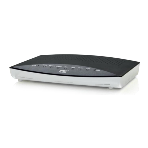
Front Panel The front panel of this device will be described here which cover all front panel definitions of other models. Figure 2: Front Panel and LEDs Connector and LED definitions from left to right: Label Color Function GREEN off: No power Power Green GREEN on: Power on... -
Page 10: Rear Panel
Rear Panel The rear panel of this device will be described here which cover all rear panel definitions of other models. Figure 3: Rear Panel Connections Connector definition: Label Function Power Switch ON/OFF switch Power Jack Connects to the supplied power adapter Connects to the USB devices TEL 1 ~ TEL2 Connects to analog telephones for VoIP service... -
Page 11: Connecting Your Device
Connecting your device This chapter provides basic instructions for connecting the device to a computer or LAN and to the Internet. In addition to configuring the device, you need to configure the Internet properties of your computer(s). For more details, see the following sections in Appendix A: This chapter assumes that you have already subscribed a broadband service with your Internet service provider (ISP). -
Page 12: Step 1. Connect The Wan Port To The Fiber Network Or Broadband Device Like Dsl Modem, Cable Modem Or Fiber Modem
Step 1. Connect the WAN port to the fiber network or broadband device like DSL modem, cable modem or fiber modem Connect the WAN port to fiber network or the broadband device like DSL modem, cable modem or fiber modem which has the high speed internet connection. Step 2. -
Page 13: Getting Start With The Web Pages
Getting Start with the Web pages The device includes a series of Web pages that provide an interface to the software installed on the device. It enables you to configure the device settings to meet the needs of your network. You can access it through a web browser on a PC connected to the device. - Page 14 Advanced Setup: provides information about the current configuration of various system features with options to change the configuration. It includes the sub menus Layer2 Interface, WAN service, LAN, NAT, Security, Parental Control, Quality of Service, Routing, DNS Proxy, Print Server, DLNA, Storage service, Interface Grouping, IP Tunnel, IPSec, Certificate, Power Management and Multicast.
- Page 15 Voice Setup: provides the VoIP Setup. It includes the sub menus, Interface Setup, SIP Basic Setting and SIP Advanced Setting. Diagnostic: provides the diagnostic utility to check the LAN and Wireless physical connection and WAN connection as well. Management: provides the administration utilities. It includes the sub menus, Settings, System Log, Security Log, TR-069 Client, Internet Time, Access Control, Update Software, Reboot and Logout.
-
Page 16: Testing Your Setup
Testing your Setup Once you have connected your hardware and configured your PCs, any computer on your LAN should be able to use the device to access the Internet. To test the connection, turn on the device, wait seconds till device booting up and then verify that the LEDs are illuminated as follows: Behavior Power... - Page 17 Option Default Setting Explanation/Instructions User/Password admin/admin User name and password to access the device LAN Port Assigned static IP This is the IP address of the LAN port IP Address address: on the device. The LAN port connects 192.168.1.1 the device to your Ethernet network. Typically, you will not need to change this address.
-
Page 18: Device Information
Device Information The Device Information web page menu includes the following submenus: Summary Statistics Route DHCP Voice. Summary The Summary Page of the device shows the following information, Board ID, Build Timestamp, Software version, Bootloader version, Wireless driver version, Voice driver version and device uptime. -
Page 19: Wan
The WAN information of the device shows detailed information about the WAN connection such as VLAN ID, WAN port service information, Protocol, IPv6 enabled or disabled, IGMP enabled or disabled, Quality of Service enabled or disabled, IP address of WAN port and so on. Figure 7: WAN Port Information Statistic The Statistic Page of the device shows the following information of LAN, WLAN and... -
Page 20: Arp
Figure 10: Device Route Table Information The ARP Page of the device shows the ARP table mapping the IP address and related MAC address. The ARP table contains IP address, Flag, MAC address, Device Interface. Figure 11: Device ARP Table Information DHCP The DHCP Page of the device shows the DHCP table which DHCP server of device assigns the IP address to the PC requesting an IP address. - Page 21 Figure 13: Device Voice Status...
-
Page 22: Advanced Setup
Advanced Setup The Advance Setup menu includes the sub menus Layer2 Interface, WAN service, LAN, NAT, Security, Parental Control, Quality of Service, Routing, DNS Proxy, Print Server, DLNA, Storage service, Interface Grouping, IP Tunnel, IPSec, Certificate, Power Management and Multicast. Layer2 Interface WAN Service Security... -
Page 23: Wan Service
In this page, please select an ETH port from the list, usually select the “eth4/WAN” as WAN layer2 interface. Figure 15: Add a Layer 2 WAN Interface Page To configure ETH WAN (Layer 2 interface) configuration: Select an ETH port from the list. ... - Page 24 Figure 17: WAN Service Setup – Select a layer 2 interface Click “Next” to continue the configuration. The parameters of each following page will be varied and depended on the WAN layer 2 interface (default mode or VLAN MUX mode). Most of cases the VLAN MUX mode covers the settings of default mode. The VLAN MUX mode will be introduced and described in details.
-
Page 25: Ppp Over Ethernet (Pppoe)
PPP over Ethernet (PPPoE) Figure 19: WAN Connection, PPPoE Configuration To configure the PPPoE settings: Enter the User’s PPP Username and Password Enter the Service Name if any Select the Authentication Method used during negotiation, default is AUTO. ... - Page 26 Configure the default routing (gateway) WAN interface and click “Next”. Figure 20: WAN Service Default Routing Configuration Figure 21: WAN Service DNS server Configuration To configure WAN DNS Server Configuration: Check to use Select DNS server interface from the available WAN interfaces or “use the following Static DNS IP address”...
-
Page 27: Ip Over Ethernet
Figure 22: WAN Setup Summary The WAN Setup Summary page as previous WAN Setup Summary figure shows all of parameters. Click Apply/Save if correct or click Back to restart the configuration again. IP over Ethernet Figure 23: WAN Connection, IP over Ethernet Configuration To configure the IP over Ethernet settings: ... -
Page 28: Bridging
Figure 24: Network Address Translation Configuration Global Settings: Check to Enable NAT if PCs in the LAN share the same WAN port IP address to surf Internet Check to Enable Firewall if you need the device to do the first firewall protection ... -
Page 29: Lan
Figure 26: LAN Configuration Global Settings: Select the Group Name from the list Enter the IP address which the CPE in the LAN will use to connect to the device. For example, enter 192.168.1.1 Enter the Subnet Mask. For example, enter 255.255.255.0 ... -
Page 30: Ipv6 Autoconfig
interface if there are two separated networks in the LAN sharing the device to surf Internet. Then enter the second IP address and subnet mask. Click Apply/Save to save setting or Save/Reboot to save and then reboot the device IPv6 Autoconfig IPv6 is supported in this device. -
Page 31: Virtual Server
Virtual Server Virtual Server enables you to run a server on your local network that can be accessed from the remote parties. You need to set up a rule to tell the device on which computer the server is held. When port virtual server is enabled, your router (the device) routes all the inbound traffic on a particular port to the chosen computer on your network. -
Page 32: Port Triggering
Enter the Start Internal Port # and End Internal Port # that may use different port # to secure the service. If you use the same port # as external port #, please leave Internal Port # as blank. ... -
Page 33: Dmz Host
Global Setting Select Use Interface from the list Select a Application Name from the predefined list or enter the name of Custom Application Enter the Start Trigger Port # and End Trigger Port # that open to remote to access the service ... - Page 34 Figure 33: Outgoing IP Filter Settings Click Add to add a rule of Outgoing IP Filtering. Check Remove and click Remove to remove the specified entry. Figure 34: Add - Outgoing IP Filter Configuration Global Setting Enter the Filter Name ...
- Page 35 By default, all incoming IP packets from WAN are blocked to access PCs in LAN, but some IP packets can be accepted by setting up filters. Figure 35: Incoming IP Filter Status Click Add to add a rule of Incoming IP Filtering. Check Remove and click Remove to remove the specified entry.
-
Page 36: Parental Control
packet Enter the one port or multi ports (port range) Select the WAN interfaces which will be applied with this incoming IP filter rule. Click Apply/Save Parental Control This feature allows you to configure some of PCs in LAN to surf Internet in specific time period. -
Page 37: Url Filter
Select the Browser’s MAC Address or Other MAC Address to enter the specific PC MAC address. Check those days you want to block above PC to surf Internet. Enter the Start Blocking Time and End Blocking Time ... -
Page 38: Quality Of Service
Quality of Service The Quality of Service feature provides a method to prioritize the packet and arrange a better efficiency of bandwidth. In other words, some traffic such as voice or video has handled as higher priority than others such as data to get near real time response. Figure 40: Quality of Service Configuration Global Setting ... -
Page 39: Qos Classification
Click Add to add a QoS queue. The Enable button will scan through the every rule in the table. Rule with Enable-checkbox checked will be enabled. Check Remove and click Remove to remove the specified entry. Figure 42: Add a QoS Queue Global Setting ... - Page 40 Figure 44: Add a QoS Classification The screen creates a traffic class rule to classify the upstream traffic, assign queue priority which defines the precedence and type of service. A rule consists of a class name and at least one condition below. All of the specified conditions in this classification rule must be satisfied for the rule to take effect.
-
Page 41: Routing
Set Rate Limit (Kbps) Click Apply/save to add this QoS class Routing The section shows the IP addresses or address routes for the computers connected to the gateway to reach different destinations, such as the local network, the gateway, or the Internet. -
Page 42: Static Route
Static Route You could create your own routing entry by the destination network address and interface to configure the data traffic in the network. Click Add to add entry. Figure 46: Static Route Configuration Figure 47: Add a Static Route Global Setting ... -
Page 43: Rip
Figure 48: Policy Route Configuration Figure 49: Add a Policy Route Global Setting Enter the Policy Name of this configuration Select the physical LAN interface (port) from the list Enter the Source IP Address Select the Use Interface from the list ... -
Page 44: Dns
Global Setting Select the desired RIP version and operation, followed by placing a check in the 'Enabled' checkbox for the interface. Click Apply/Save to save the configuration The DNS feature provides two more setting pages including DNS server setting and Dynamic DNS. -
Page 45: Dynamic Dns
and/or secondary DNS server. If there is IPv6 WAN interface, the DNS server interface can be obtained from the selected WAN interface via checking Obtain IPv6 DNS info from a WAN interface or by enter static IP address of Primary IPv6 DNS server and/or Secondary IPv6 DNS server. -
Page 46: Print Server
Enter the Username and Password Click Apply/Save to save the configuration Print Server The Print Server feature provides you to setup a network printer in your LAN environment. Figure 54: Print Server Configuration Global Setting Check Enable On-Board Print Server checkbox ... -
Page 47: Storage Service
Select the Interface from the list Set the Media Library Path where stores the files Click Apply/Save to save the configuration Storage Service The Storage Service feature allows you to use USB storage device as a sharing storage device. -
Page 48: Interface Grouping
Enter the password again in the Confirm Password field Enter the Volumename Click Apply/Save to save the configuration Interface Grouping The page provides Interface Grouping configuration. In default, the LAN1 to LAN4, wireless and virtual wireless_guest are grouped together as a single Ethernet environment. -
Page 49: Ip Tunnel
Figure 60: Add a Group Configuration Global Setting Enter the Group Name Select the WAN Interface used in this group from the list Select the available LAN ports from available LAN interfaces into grouped interface. The selected LAN interface will be removed from its original group and joined this new group. -
Page 50: Ipv6 In Ipv4 Tunnel
IPv6 in IPv4 Tunnel Figure 61: IPv6 in IPv4 Tunnel Information Figure 62: IPv6 in IPv4 Tunnel Configuration Global Setting Enter the Tunnel Name Select the Mechanism from the list Select the Associated WAN Interface from the list ... -
Page 51: Ipsec
Figure 64: IPv4 in IPv6 Tunnel Configuration Global Setting Enter the Tunnel Name Select the Mechanism from the list Select the Associated WAN Interface from the list Select the Associated LAN interface from the list Check Manual or Automatic ... - Page 52 Figure 66: IPSec Tunnel Configuration Global Setting Enter the IPSec Connection Name Select the Tunnel Mode Enter the Remote IPSec Gateway Address Select the Tunnel Access from Local IP Address from the list (subnet or single address) and enter the IP address for VPN and Subnetmask ...
-
Page 53: Certificate
Figure 67: Advanced IPSec Tunnel Configuration There are two phases, phase 1 and phase 2 in the Advanced IKE settings. Global Setting Select Mode of phase 1 from the list Select Encryption Algorithm of phase 1 from the list ... - Page 54 Figure 69: Create Certificate Request Configuration Global Setting Enter the Certificate Name Enter the Common Name Enter the Organization Name Enter the State/Province Name Select Country/Region Name from the list Click Apply to save the configuration. Figure 70: Import Certificate Configuration...
-
Page 55: Trusted Ca
Global Setting Enter the Certificate Name Enter the Certificate Enter the Private Key Click Apply to save the configuration. Trusted CA Figure 71: Trusted CA Information Figure 72: Import Trusted CA Configuration Global Setting Enter the Certificate Name ... -
Page 56: Power Management
Power Management The Power management feature provides you the control of hardware modules to evaluate power consumption. Figure 73: Power Management Configuration Global Setting Check to enable MIPS CPU Clock divider when Idle Check to enable Wait instruction when Idle ... -
Page 57: Multicast
Multicast The Multicast feature provides you to configure detailed parameters of IGMP protocol. Figure 74: Multicast IGMP Configuration Global Setting Enter the Default Version Enter the Query Interval Enter the Query Response Interval Enter the Last Member Query Interval ... -
Page 58: Wireless Setup
Wireless Setup The Wireless Setup web page menu comprises: Basic Security MAC Filter Wireless Bridge Advanced Station Information Basic The device provides wireless connection to wireless clients. This page allows you to enable the wireless service, hide the network from active scan and set the SSID (Service Set IDentifier). -
Page 59: Security
to each other. Check to disable WMM Advertise where WMM stands for WiFi Multimedia. This technology maintains the priority of audio, video and voice applications in a Wi-Fi network so that other applications and traffic are handled in lower priority. ... - Page 60 Global Setting Select the SSID from the list, then set the related security parameters Select the method of Network Authentication. It could be OPEN (none), Shared, 802.1X, WPA, WPA-PSK, WPA2, WPA2-PSK, Mixed WPA2/WPA, Mixed WPA2/WPA-PSK Select the method of WEP Encryption if Network Authentication is Open. Select the Encryption Strength with 64bits or 128bits, select the current Key Index and enter the key and four keys when necessary if WEP Encryption is enabled.
- Page 61 If the Network Authentication is WPA, enter WPA Group Rekey Interval, the IP address and Port number of Radius server, Radius Key, WPA Encryption Method (TKIP, AES, TKIP+AES), enable or disable WEP encryption. If WEP Encryption is enabled, select the Encryption Strength with 64bits or 128bits, select the current Key Index and enter the key and four keys when necessary.
- Page 62 If the Network Authentication is WPA2-PSK (pre-shared key), enter the WPA Pre-Shared Key and enter WPA Group Rekey Interval, WPA Encryption Method (TKIP, AES, TKIP+AES), enable or disable WEP encryption. If WEP Encryption is enabled, select the Encryption Strength with 64bits or 128bits, select the current Key Index and enter the key and four keys when necessary.
-
Page 63: Mac Filter
MAC Filter Figure 77: Wireless Setting – Input MAC Address Figure 78: Wireless Setting – Define the action plan for those MAC address Global Setting Select the SSID from the list Select the MAC Restrict Mode from one of Disable (no MAC filter), Allow (only those PCs with MAC addresses in the table can surf Internet) or Deny (only those PCs with MAC addresses in the table can not surf Internet). -
Page 64: Wireless Bridge
Wireless Bridge The wireless bridge feature is also known as WDS, Wireless Distribution System). Figure 79: Wireless Bridge Configuration Global Setting Set the AP mode as Access Point or Wireless Bridge When the AP mode is set to Wireless Bridge, the Wireless Bridge Restrict determine where it can communicate with all other wireless bridges and also wireless clients (set Bridge Restrict is Disabled) or just the specified MAC addresses of below wireless bridge devices (set Bridge Restrict is Enable). -
Page 65: Advanced
Advanced This page allows you to configure advanced parameters for wireless communication. Figure 80: Wireless Setting – Advanced Global Setting Set the Wireless Communication Band. If you do not know it, please it as default. Select the channel from the list ... -
Page 66: Station Information
Set the Fragmentation Threshold values from 256 to 2364 bytes. If the value is too small, it may cause a result in poor performance. Set the RTS (Ready to Send) Threshold Set DTIM Interval. DTIM stands for Delivery Traffic Indication Message. This is a beacon and is a countdown informing wireless clients of the next window for listening to broadcast and multicast messages. -
Page 67: Voice Setup
Voice Setup The Voice Setup web page menu comprises: Interface Setup SIP Basic Setting SIP Advanced Setting Interface Setup This page allows you to specify the voice packets to pass through the specific interface and to choose different country code to pre-set voice related parameters including ringing type, ringing frequency, tone type, tone frequency, cadence, etc.. -
Page 68: Sip Basic Setting
SIP Basic Setting This page allows you to setup the SIP protocols (parameters). Figure 83: Voice Basic SIP Protocol Configuration Global Setting: Enter the SIP domain name Enter the VoIP dial plan Check to Use SIP Proxy if necessary and then enter address of SIP Proxy and SIP Proxy Port number ... - Page 69 Check to Use SIP Registrar if necessary and then enter address of SIP Registrar and SIP Registrar Port number There are two SIP accounts can be configured with following parameters, Account Enabled, Physical Endpt Id, Extension, Authentication name, Password, Preferred ptime, Preferred codec 1 to 6.
-
Page 70: Sip Advanced Setting
SIP Advanced Setting This page allows you to setup the advanced parameters of the SIP protocols. Figure 84: Voice Advanced SIP Protocol Configuration... - Page 71 Global Setting: There are two SIP accounts with call features separately. Check to enable those call features, Call waiting, Call forwarding number, Forward unconditionally, Forward on “busy”, Forward on “no answer”, Message waiting indication (MWI), Three-way conference, and Anonymous calling (CLIR). ...
-
Page 72: Diagnostic
Diagnostic Diagnostic This page allows you to diagnostic the connections of LAN, Wireless and WAN ports. Figure 85: Diagnostic Click Run Diagnostic to run the test script and get the diagnostic result. -
Page 73: Management
Management The Management web page menu comprises: Settings System Log Security Log TR-069 Client Internet Time Access Control Update Software Reboot Logout Settings This page allows you to backup the current configuration of the device, update the configuration, and restore default configuration (factory setting). Figure 86: Backup Settings Click Backup Settings to backup the current settings of the device into file in PC. -
Page 74: System Log
Figure 88: Restore Default Settings To click Restore Default Settings to restore the factory default settings. System Log This page allows you to view system log and also configure system log that way you want to see. Figure 89: Management Configuration – System Log Global Setting ... -
Page 75: Security Log
Select to Enable Log function or not Select Log Level from the list Select Display Level from the list Select Mode from the list Click Apply/Save to save the configuration. Security Log This page allows you to view security log. Figure 91: Management Configuration –... -
Page 76: Internet Time
Global Setting Select to Enable or Disable to send Inform packet to ACS. Enter the Inform Interval number of seconds. The Inform packet will be sent to ACS periodically. Enter the ACS URL to reach ACS Enter the ACS User Name and Password ... -
Page 77: Access Control
Access Control This submenu provides you local (LAN) or remote (WAN) access to the device. This may help the IT support staff to configure the router locally or remotely. IP Address Figure 94: Access Control: IP Address Click to enable or disable Access Control by IP address. Click Add to add IP address. -
Page 78: Service
Service Figure 96: Access Control: Service Global Setting: Specify the method by which you wish to access the router locally or remotely by selecting it. The following are the methods available for local and remote access: HTTP ... -
Page 79: Update Software
Figure 97: Access Control: Password Global Setting: Enter the Username Enter the Old Password Enter the New Password and Confirm Password Click Apply/Save to save the configuration. Update Software This page allows you to upgrade the software (firmware). Figure 98: Update Software Global Setting: ... -
Page 80: Logout
Logout This page allows you to save current configuration and reboot to use the settings. Figure 100: Logout Global Setting Click Logout to leave the device’s configuration page ... -
Page 81: Appendix A - Configuring The Internet Settings
Appendix A - Configuring the Internet Settings This appendix provides instructions for configuring the Internet settings on your computers to work with the device. Configuring Ethernet PCs Assigning static Internet information to your PCs If you are a typical user, you will not need to assign static Internet information to your LAN PCs because your ISP automatically assigns this information for you. -
Page 82: Configuring Wireless Pcs
Configuring Wireless PCs You need to configure the operating system installed on your Wireless PCs using the same procedure described for Configuring Ethernet PCs section. Positioning the wireless PCs The wireless network cards used determine the maximum distance between your wireless PCs and your device. -
Page 83: Appendix B - Troubleshooting
EG102 User’s Guide Appendix B - Troubleshooting This appendix suggests solutions for problems you may encounter in installing or using the device, and provides instructions for using several IP utilities to diagnose problems. Contact Customer Support if these suggestions do not resolve the problem. Troubleshooting Suggestions Problem Troubleshooting Suggestion... -
Page 84: Diagnosing Problem Using Ip Utilities
Problem Troubleshooting Suggestion I forgot/lost my user ID or If you have not changed the password from the default, try using “admin” as both the user ID password. and password. Otherwise, you can reset the device to the default configuration by pressing three times the Reset Default button on the front panel of the device. -
Page 85: Nslookup
You can also test whether access to the Internet is working by typing an external address, such as that for www.yahoo.com (216.115.108.243). If you do not know the IP address of a particular Internet location, you can use the nslookup command, as explained in the following section. -
Page 86: Appendix C - Specification
EG102 User’s Guide Appendix C - Specification A1. Hardware Specifications LAN Interface Four port 10/100BaseT Ethernet Switch (4 * RJ-45 connectors), IEEE 802.3u with MDI/MDIX auto-detection Integrated 802.11b/g WLAN Access Point WAN Active Ethernet Optical Interface ... - Page 87 Firewall Support NAT and DMZ Virtual server (port mapping) and IP filters Protection against IP and MAC address spoofing UPnP NAT traversal and VPN / IPSec pass-through Voice Support voice CODECs like G.711, G.726, G.729A/B, BV16, ILBC, T.38 etc ...
-
Page 88: Appendix D - Regulation
But if it does, the user will be required to correct the interference at his or her own expense. The authority to operate this equipment is conditioned by the requirement that no modifications will be made to the equipment unless CTC Union expressly approves the changes or modifications. - Page 89 FCC Part 68 Notice This equipment complies with Part 68 of FCC Rules. On the base unit of this equipment is a label that contains, among other information, the FCC Registration Number and Ringer Equivalence Number (REN) for this equipment. IF REQUESTED, THIS INFORMATION MUST BE GIVEN TO THE TELEPHONE COMPANY.
- Page 90 UL Safety Regulations Disconnect TNV circuit connector or before removing cover or equivalent. Disconnect TNV circuit connector(s) before disconnecting power. Do not use this product near water for example, near a bathtub, washbowl, and kitchen sink or laundry tub, in a wet basement, or near a swimming pool. ...
Need help?
Do you have a question about the GW-632FW and is the answer not in the manual?
Questions and answers