Table of Contents
Advertisement
Quick Links
Advertisement
Table of Contents

Related Manuals for CTC Union FRM220-MSW404


Summary of Contents for CTC Union FRM220-MSW404
- Page 1 FRM220-MSW404 L2+ OAM Managed Carrier Ethernet Switch...
- Page 2 CTC Union Technologies makes no warranty, representation, or guarantee regarding the suitability of its products for any particular purpose, nor does CTC Union assume any liability arising out of the application or use of any product and specifically disclaims any and all liability, including without limitation any consequential or incidental damages.
- Page 3 This document is the current official release manual. Contents are subject to change without prior notice. Please check CTC Union's website for any updated manual or contact us by E-mail at sales@ctcu.com. Please address any comments for improving this manual or to point out omissions or errors to marketing@ctcu.com. Thank you.
-
Page 4: Table Of Contents
TABLE OF CONTENTS CHAPTER 1. INTRODUCTION ....................... 9 1.1 W ............................9 ELCOME 1.2 P ........................9 RODUCT ESCRIPTION 1.3 P ........................9 RODUCT PECIFICATIONS 1.4 P ............................10 ANEL 1.4.1 LED ................................... 10 1.4.2 Default Push Button ............................11 CHAPTER 2. - Page 5 TABLE OF CONTENTS 3.4.3.5 SNMPv3 Group Configuration ............................40 3.4.3.6 SNMPv3 View Configuration ............................40 3.4.3.7 SNMPv3 Access Configuration ............................41 3.4.4 RMON ................................42 3.4.4.1 RMON Statistics Configuration .............................42 3.4.4.2 RMON History Configuration ............................42 3.4.4.3 RMON Alarm Configuration ............................43 3.4.4.4 RMON Event Configuration ............................44 3.4.4.5 RMON Statistics Overview ............................44 3.4.4.6 History Overview ................................45 3.4.4.7 Alarm Overview ................................46...
- Page 6 TABLE OF CONTENTS 3.6.6 Remote Device ..............................83 3.7 L ........................... 84 ROTECTION 3.7.1 Configuration ..............................84 3.7.2 Status ................................85 3.8 S ..........................85 PANNING 3.8.1 Bridge Settings ..............................86 3.8.2 MSTI Mapping ..............................88 3.8.3 MSTI Priorities ..............................89 3.8.4 CIST Ports .................................
- Page 7 TABLE OF CONTENTS 3.20 VCL ............................136 3.20.1 MAC-based..............................136 3.20.1.1 Membership Configuration ............................136 3.20.1.2 Membership Status ..............................137 3.20.2 Protocol-based VLAN ........................... 137 3.20.2.1 Protocol to Group ..............................137 3.20.2.2 Group to VLAN ................................138 3.20.3 IP Subnet-based VLAN ..........................139 3.21 V VLAN ..........................
- Page 8 TABLE OF CONTENTS 3.30.4.2 Download .................................176 3.30.4.3 Upload ..................................176 3.30.4.4 Activate ..................................177 3.30.4.5 Delete ..................................177...
-
Page 9: Chapter 1. Introduction
CHAPTER 1. INTRODUCTION 1.1 Welcome Thank you for choosing FRM220-MSW404 L2 OAM Managed Switch. This manual is used to explain the hardware installation procedures and operation of FRM220-MSW404, and to present its capabilities and specifications. This manual is divided into 3 chapters, the Introduction, Installation and Web Based Provisioning chapters. Installers should carefully read Chapter 1 &... -
Page 10: Panel
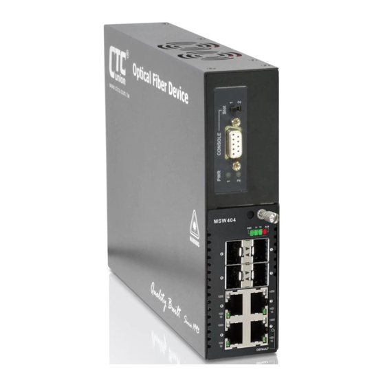
1000 1000 1000 1000 Figure1. FRM220-MSW404 Front Panel SFP Slots PWR, T1, T2, ALM LED indicators RJ-45 UTP Ports Default push button 1.4.1 LED Color Status Definition Green Power is on. Power is not connected. -
Page 11: Default Push Button
CHAPTER 1 INTRODUCTION 1.4.2 Default Push Button The “Default” push button is located next to RJ-45 UTP port. It is used to recover lost password or to return TCP/IP settings to factory default values. Use a pencil or blue-point pen and then press the button for 3 seconds then release to reset the device to the factory default settings. -
Page 12: Chapter 2. Installation
CHAPTER 2. INSTALLATION 2.1 Chassis Option FRM220-MSW404 card can be placed in FRM220 series chassis, including the two-slot CH02M, CH02-NMC, CH04A, CH08 or the full twenty-slot CH-20 chassis. Chassis with built-in power are available with single AC (100~240VAC), single DC (18~75VDC), dual AC, dual DC or AC plus DC combo. -
Page 13: Electrical Installation For Chassis
CHAPTER 2 INSTALLATION 2.2 Electrical Installation for Chassis With a built-in AC power chassis, AC power is supplied to the chassis through a standard IEC C14 3-prong receptacle, located on the rear of the chassis. Any detachable nationally approved power cord with IEC C13 line plug may be used to connect AC power to the chassis unit. -
Page 14: Chapter 3. Web Operation & Configuration
3.1 Home Page Using Internet Explorer (Version 9.0 or above is recommended), Firefox, Chrome or other stable web browser, enter the IP address of the FRM220-MSW404 in the browser's location bar. The factory default address is 10.1.1.1. 3.1.1 Login A standard login prompt will appear depending on the type of browser used. The example below is with Firefox browser. -
Page 15: Port Status
3.1.4 Help System The FRM220-MSW404 Series has an online "help" system to aid the engineer when setting the parameters of the device. Each functional setting page is accompanied by a specific "help" for that functional page. The user can display this help "pop up"... -
Page 16: System
CHAPTER 3 Chapter 4. Web Configuration & Operation WEB OPERATION & CONFIGURATION For the remainder of this section, each menu item will be explained one by one, in order as they descend down the menu screen, starting with the "System" menu. 3.2 System The configuration under the "System"... -
Page 17: System Information
CHAPTER 3 Chapter 4. Web Configuration & Operation WEB OPERATION & CONFIGURATION 3.2.2 System Information The system information screen will display the configuration information, the hardware MAC address and version, the system time, the system "uptime" and the software version and build date. 3.2.3 System IP Setup the IP configuration, interface and routes. - Page 18 CHAPTER 3 Chapter 4. Web Configuration & Operation WEB OPERATION & CONFIGURATION DNS Proxy: When DNS proxy is enabled, the system will relay DNS requests to the currently configured DNS server, and reply as a DNS resolver to the client devices on the network. IP Interface Click "Add Interface"...
-
Page 19: System Ip Status
CHAPTER 3 Chapter 4. Web Configuration & Operation WEB OPERATION & CONFIGURATION 3.2.4 System IP Status Display the status of IP interfaces and routes. Please refer to “System IP” for the configuration of the interfaces and routes. This page is informational only. 3.2.5 System NTP Setup the Network Time Protocol configuration, to synchronize the device’s clock to network time. -
Page 20: System Time
CHAPTER 3 Chapter 4. Web Configuration & Operation WEB OPERATION & CONFIGURATION '::192.1.2.34'. The NTP servers are tried in numeric order. If 'Server 1' is unavailable, the NTP client will try to contact 'Server 2'. 3.2.6 System Time Setup the device time. The setting example above is for Eastern Standard Time in the United States. -
Page 21: System Log Configuration
CHAPTER 3 Chapter 4. Web Configuration & Operation WEB OPERATION & CONFIGURATION Offset settings: Enter the number of minutes to add during Daylight Saving Time. The allowed range is 1 to 1440. 3.2.7 System Log Configuration Configure System Log on this page. Server Mode: This sets the server mode operation. -
Page 22: System Detailed Log
CHAPTER 3 Chapter 4. Web Configuration & Operation WEB OPERATION & CONFIGURATION 3.2.9 System Detailed Log Displays individual log records. View each log, by ID number. 3.2.10 System CPU Load This page displays the CPU load, using an SVG graph. The load is measured as averaged over the last 100ms, 1sec and 10 seconds intervals. -
Page 23: Ports
CHAPTER 3 Chapter 4. Web Configuration & Operation WEB OPERATION & CONFIGURATION 3.3 Ports Configurations related to the fiber and electrical ports are performed under the Ports menu. 3.3.1 Ports Configuration This page displays current port configurations and allows some configuration here. Port: This device has three fiber optical ports (for SFP modules) numbered 1~3 and one electrical LAN ports numbered 4. - Page 24 CHAPTER 3 Chapter 4. Web Configuration & Operation WEB OPERATION & CONFIGURATION Disabled: Disables the switch port operation. Auto: Port auto negotiating speed with the link partner, selecting the highest speed that is compatible with the link partner and negotiating the duplex mode. 10Mbps HDX: Forces the port to 10Mbps half duplex mode.
-
Page 25: Ports State
CHAPTER 3 Chapter 4. Web Configuration & Operation WEB OPERATION & CONFIGURATION MEP Instance: The port Link Loss Forwarding depends on MEP instance. MEP Logic: MEP instance logic of all Peer MEP ID. Example 1: Port 1 Tx off if any port 2, 3, 4 Rx loss: Select “OR”... -
Page 26: Ports Qos Statistics
CHAPTER 3 Chapter 4. Web Configuration & Operation WEB OPERATION & CONFIGURATION Filtered: The number of received frames filtered by the forwarding process. The counter display can be updated by clicking the "Refresh" button. When "Auto-refresh" is checked, the display will be updated every 3 seconds. -
Page 27: Ports Detailed Statistics
CHAPTER 3 Chapter 4. Web Configuration & Operation WEB OPERATION & CONFIGURATION IPv4: The QCE will match only IPV4 frames. IPv6: The QCE will match only IPV6 frames. Port: Indicates the list of ports configured with the QCE. Action: Indicates the classification action taken on ingress frame if parameters configured are matched with the frame's content. - Page 28 CHAPTER 3 Chapter 4. Web Configuration & Operation WEB OPERATION & CONFIGURATION Rx and Tx Octets: The number of received and transmitted (good and bad) bytes. Includes FCS, but excludes framing bits. Rx and Tx Unicast: The number of received and transmitted (good and bad) unicast packets. Rx and Tx Multicast: The number of received and transmitted (good and bad) multicast packets.
-
Page 29: Ports Sfp
CHAPTER 3 Chapter 4. Web Configuration & Operation WEB OPERATION & CONFIGURATION 3.3.7 Ports SFP This page displays current SFP status for all three fiber ports. Vendor Name: SFP vendor (manufacturer's) name. Vendor Part Number: Manufacture's part number, provided by SFP vendor. Fiber Type: Fiber type of either single or multi mode. -
Page 30: Security
CHAPTER 3 Chapter 4. Web Configuration & Operation WEB OPERATION & CONFIGURATION 3.4 Security Under the security heading are three major icons, switch, network and RADIUS. 3.4.1 Switch 3.4.1.1 Users This page provides an overview of the current users. Currently the only way to login as another user on the web server is to close and reopen the browser. -
Page 31: Privilege Levels
CHAPTER 3 Chapter 4. Web Configuration & Operation WEB OPERATION & CONFIGURATION Privilege Level: Select the appropriate privilege level for this user account. The allowed range is 1 to 15. If the privilege level value is 15, it can access all groups, i.e. that is granted the fully control of the device. But other values need to refer to each group privilege level. -
Page 32: Auth Method
CHAPTER 3 Chapter 4. Web Configuration & Operation WEB OPERATION & CONFIGURATION configuration/execute read-write status/statistics read-only status/statistics read-write (e.g. for clearing of statistics) User Privilege should be the same or greater than the authorization Privilege level to have access to that group. 3.4.1.3 Auth Method This page allows you to configure how users are authenticated when they log into the switch via one of the management client interfaces. -
Page 33: Ssh
CHAPTER 3 Chapter 4. Web Configuration & Operation WEB OPERATION & CONFIGURATION 3.4.1.4 SSH Configure SSH on this page. Mode: Indicates the SSH mode operation. Possible modes are: Enabled: Enable SSH mode operation. By default, SSH mode operation is enabled. Disabled: Disable SSH mode operation. -
Page 34: Access Management
CHAPTER 3 Chapter 4. Web Configuration & Operation WEB OPERATION & CONFIGURATION 3.4.2 Access Management 3.4.2.1 Access Management Configuration Configure the access management table on this page. The maximum number of entries is 16. If the application's type matches any one of the access management entries, it will be allowed access to the switch. Mode: Indicates the access management mode operation. -
Page 35: Snmp
CHAPTER 3 Chapter 4. Web Configuration & Operation WEB OPERATION & CONFIGURATION Interface: The interface type through which any remote host can access the switch. Received Packets: The number of received packets from the interface when access management mode is enabled. Allowed Packets: The number of allowed packets from the interface when access management mode is enabled. -
Page 36: Trap Configuration
CHAPTER 3 Chapter 4. Web Configuration & Operation WEB OPERATION & CONFIGURATION 3.4.3.2 Trap Configuration Configure SNMP trap on this page. Global Settings Mode: Globally enable or disable trap function. Click the “Add New Entry” to insert a SNMP trap entry. SNMP Trap Configuration Trap Config Name: Indicates a descriptive name for this SNMP trap entry. - Page 37 CHAPTER 3 Chapter 4. Web Configuration & Operation WEB OPERATION & CONFIGURATION Disabled: Disable SNMP trap mode operation. Trap Version: Indicates the SNMP trap supported version. Possible versions are: SNMP v1: Set SNMP trap supported version 1. SNMP v2c: Set SNMP trap supported version 2c. SNMP v3: Set SNMP trap supported version 3.
-
Page 38: Snmpv3 Community Configuration
CHAPTER 3 Chapter 4. Web Configuration & Operation WEB OPERATION & CONFIGURATION Link Up: none/specific/all switches Link up trap. Link Down: none/specific/all switches Link down trap. LLDP: none/specific/all switches LLDP (Link Layer Discovery Protocol) trap. When the "specific" radio button is selected, a popup graphic with port checkboxes allows selection specific ports. AAA: AAA stands for Authentication, Authorization and Accounting. -
Page 39: Snmpv3 User Configuration
CHAPTER 3 Chapter 4. Web Configuration & Operation WEB OPERATION & CONFIGURATION 3.4.3.4 SNMPv3 User Configuration Configure SNMPv3 user table on this page. The entry index keys are Engine ID and User Name. Engine ID: An octet string identifying the engine ID that this entry should belong to. The string must contain an even number (in hexadecimal format) with number of digits between 10 and 64, but all-zeros and all-'F's are not allowed. -
Page 40: Snmpv3 Group Configuration
CHAPTER 3 Chapter 4. Web Configuration & Operation WEB OPERATION & CONFIGURATION AES: An optional flag to indicate that this user uses AES authentication protocol. Privacy Password: A string identifying the privacy password phrase. The allowed string length is 8 to 32, and the allowed content is ASCII characters from 0x21 to 0x7E. -
Page 41: Snmpv3 Access Configuration
CHAPTER 3 Chapter 4. Web Configuration & Operation WEB OPERATION & CONFIGURATION View Name: A string identifying the view name that this entry should belong to. The allowed string length is 1 to 32, and the allowed content is ASCII characters from 0x21 to 0x7E. View Type: Indicates the view type that this entry should belong to. -
Page 42: Rmon
CHAPTER 3 Chapter 4. Web Configuration & Operation WEB OPERATION & CONFIGURATION 3.4.4 RMON 3.4.4.1 RMON Statistics Configuration Configure RMON Statistics table on this page. The entry index key is ID. Delete: Check to delete the entry. It will be deleted during the next save. ID: Indicates the index of the entry. -
Page 43: Rmon Alarm Configuration
CHAPTER 3 Chapter 4. Web Configuration & Operation WEB OPERATION & CONFIGURATION 3.4.4.3 RMON Alarm Configuration RMON Alarm configuration defines specific criteria that will generate response events. It can be set to test data over any specified time interval and can monitor absolute or changing values. Alarms can also be set to respond to rising or falling thresholds. -
Page 44: Rmon Event Configuration
CHAPTER 3 Chapter 4. Web Configuration & Operation WEB OPERATION & CONFIGURATION Click the “Delete” button to remove a newly-inserted entry or select the checkbox to remove a saved entry during the next save. Click the “Save” button to save settings or changes. Click the “Reset”... -
Page 45: History Overview
CHAPTER 3 Chapter 4. Web Configuration & Operation WEB OPERATION & CONFIGURATION ID: Display an ID index. Data Source: Port ID to Monitor. Drop: The total number of dropped packets due to lack of resources. Octets: The total number of octets of data received. Pkts: The total number of packets (including bad packets, broadcast packets) received. -
Page 46: Alarm Overview
CHAPTER 3 Chapter 4. Web Configuration & Operation WEB OPERATION & CONFIGURATION Multicast: The total number of good packets received that were directed to a multicast address. CRC Errors: The total number of packets received that had a length (excluding framing bits, but including FCS octets) of between 64 and 1518 octets. -
Page 47: Event Overview
CHAPTER 3 Chapter 4. Web Configuration & Operation WEB OPERATION & CONFIGURATION 3.4.4.8 Event Overview Event Index: Display the event entry index. Log Index: Display the log entry index. Log Time: Display Event log time. Log Description: Display Event description. 3.4.5 Network 3.5.5.1 Port Security Port Security Limit Control can restrict the number of users that can access the switch based on users’... - Page 48 CHAPTER 3 Chapter 4. Web Configuration & Operation WEB OPERATION & CONFIGURATION System Configuration Mode: Enable or disable port security limit control globally. If globally disabled, other modules may still use the underlying functionality, but limit checks and corresponding actions are disabled. Aging Enabled: If enabled, secured MAC addresses are subject to aging as discussed under Aging Period.
-
Page 49: Switch Status
CHAPTER 3 Chapter 4. Web Configuration & Operation WEB OPERATION & CONFIGURATION 3.4.5.1.2 Switch Status User Module Legend User Module Name: The full name of a module that may request Port Security services. Abbr: This column is the abbreviation for the user module used in the “Users” column in the “Port Status”. Port Status Port: The port number. -
Page 50: Port Status
CHAPTER 3 Chapter 4. Web Configuration & Operation WEB OPERATION & CONFIGURATION 3.4.5.1.3 Port Status This page shows MAC addresses learned on a particular port. MAC Address: When “Port Security Limit Control” is enabled globally and on a port, MAC addresses learned on a port show in here. -
Page 51: Configuration
CHAPTER 3 Chapter 4. Web Configuration & Operation WEB OPERATION & CONFIGURATION 3.4.5.2.1 Configuration System Configuration Mode: Enable 802.1X and MAC-based authentication globally on the switch. If globally disabled, all ports are allowed to forward frames. Reauthentication Enabled: Select the checkbox to set clients to be re-authenticated after an interval set in "Reauthentication Period"... - Page 52 CHAPTER 3 Chapter 4. Web Configuration & Operation WEB OPERATION & CONFIGURATION Guest VLAN ID: This VLAN ID is functional only when Guest VLAN is enabled. This is the value that a port’s Port VLAN ID is set to if a port is moved into the Guest VLAN. The range is 1~4095. Max.
-
Page 53: Switch Status
CHAPTER 3 Chapter 4. Web Configuration & Operation WEB OPERATION & CONFIGURATION Multi 802.1X: In Multi 802.1X, one or more supplicants can get authenticated on the same port at the same time. Each supplicant is authenticated individually and secured in the MAC table using the “Port Security” module. MAC-based Auth.: Unlike port-based 802.1X, MAC-based authentication do not transmit or receive EAPOL frames. -
Page 54: Port Statistics
CHAPTER 3 Chapter 4. Web Configuration & Operation WEB OPERATION & CONFIGURATION Port: The port number. Click a port to view the detailed NAS statistics. Admin State: Display the port’s current administrative state. Port Status: Display the port state. Last Source: The source MAC address carried in the most recently received EAPOL frame for EAPOL-based authentication. -
Page 55: Acl
CHAPTER 3 Chapter 4. Web Configuration & Operation WEB OPERATION & CONFIGURATION Responses: The number of valid EAPOL response frames (other than Response Identity frames) that have been received by the switch. Start: The number of EAPOL Start frames that have been received by the switch. Logoff: The number of valid EAPOL Logoff frames that have been received by the switch. - Page 56 CHAPTER 3 Chapter 4. Web Configuration & Operation WEB OPERATION & CONFIGURATION Policy ID: Assign an ACL policy ID to a particular port. A port can only use one policy ID; however, a policy ID can apply to many ports. The default ID is 0. The allowed range is 0~255. Action: Permit or deny a frame based on whether it matches a rule defined in the assigned policy.
-
Page 57: Rate Limiters
CHAPTER 3 Chapter 4. Web Configuration & Operation WEB OPERATION & CONFIGURATION 3.4.5.3.2 Rate Limiters Rate Limiter ID: Display every rate limiter ID. Rate: Specify the threshold above which packets are dropped. The allowed values are 0~3276700 pps or 1, 100, 200, 300…1000000 kbps. - Page 58 CHAPTER 3 Chapter 4. Web Configuration & Operation WEB OPERATION & CONFIGURATION Mirror: Display mirror function is enabled or disabled. Counter: Display the number of frames that have matched any of the rules defined for this ACL. Click the plus sign to add a new ACE entry. ACE Configuration Ingress Port: Select the ingress port of the access control entry.
- Page 59 CHAPTER 3 Chapter 4. Web Configuration & Operation WEB OPERATION & CONFIGURATION Any: No VLAN ID filter is specified (Don’t care). Specific: Specify a VLAN ID. A frame with the specified VLAN ID matches this ACE rule. Tag Priority: Select the User Priority value found in the VLAN tag to match this rule. MAC Parameter SMAC Filter: The type of source MAC address.
- Page 60 CHAPTER 3 Chapter 4. Web Configuration & Operation WEB OPERATION & CONFIGURATION Network: Specify the sender IP address and sender IP mask. Target IP Filter: Specify the destination IP address. Any: No target IP filter is specified. Host: Specify the target IP address. Network: Specify the target IP address and target IP mask.
-
Page 61: Acl Status
CHAPTER 3 Chapter 4. Web Configuration & Operation WEB OPERATION & CONFIGURATION DIP Address: Specify a destination IP address. DIP Mask: Specify a destination subnet mask. IPv6 Parameters Next Header Filter: Select next header filter option. Available options include ICMP, UDP, TCP, Other. SIP Filter: Select a source IP filter. -
Page 62: Dhcp
CHAPTER 3 Chapter 4. Web Configuration & Operation WEB OPERATION & CONFIGURATION Action: Display the forwarding action of the ACE. Permit: Frames matching the ACE may be forwarded and learned. Deny: Frames matching the ACE may be forwarded and learned. Filtered: Frames matching the ACE are filtered. -
Page 63: Snooping Configuration
CHAPTER 3 Chapter 4. Web Configuration & Operation WEB OPERATION & CONFIGURATION 3.4.5.4.1 Snooping Configuration DHCP Snooping Configuration Snooping Mode: Enable or disable DHCP Snooping function globally. When DHCP snooping mode operation is enabled, the DHCP request messages will be forwarded to trusted ports and only allow reply packets from trusted ports. Port Mode Configuration Port: Port number. -
Page 64: Relay Statistics
CHAPTER 3 Chapter 4. Web Configuration & Operation WEB OPERATION & CONFIGURATION Replace: Replace the DHCP client packet information with the switch’s relay information. This is the default setting. Keep: Keep the client’s DHCP information. Drop: Drop the packet when it receives a DHCP message that already contains relay information. 3.4.5.4.3 Relay Statistics DHCP Relay Statistics Transmit to Server: The number of packets that are relayed from client to server. -
Page 65: Ip Source Guard
CHAPTER 3 Chapter 4. Web Configuration & Operation WEB OPERATION & CONFIGURATION Drop Agent Option: The number of packets that were dropped which were received with relay agent information. 3.4.5.5 IP Source Guard 3.4.5.5.1 Configuration IP Source Guard Configuration Mode: Enable or disable IP source guard globally. Translate dynamic to static: Click this button to translate dynamic entries to static ones. -
Page 66: Dynamic Table
CHAPTER 3 Chapter 4. Web Configuration & Operation WEB OPERATION & CONFIGURATION Port: Select a port to which a static entry is bound. VLAN ID: Enter VLAN ID that has been configured. IP Address: Enter a valid IP address. MAC Address: Enter a valid MAC address. Click the “Add New Entry”... -
Page 67: Vlan Configuration
CHAPTER 3 Chapter 4. Web Configuration & Operation WEB OPERATION & CONFIGURATION ARP Inspection Configuration Mode: Enable or disable ARP inspection function globally. Port Mode Configuration Port: The port number. “Port *” rules apply to all ports. Mode: Enable or disable ARP Inspection on a port. Please note that to make ARP inspection work, both global mode and port mode must be enabled. -
Page 68: Static Table
CHAPTER 3 Chapter 4. Web Configuration & Operation WEB OPERATION & CONFIGURATION Click the “Save” button to save newly-configured settings or changes. Click the “Reset” button to restore settings to default settings or previously configured settings. 3.4.5.6.3 Static Table Port: Select a port to which a static entry is bound. VLAN ID: Specify a configured VLAN ID. -
Page 69: Dynamic Table Status
CHAPTER 3 Chapter 4. Web Configuration & Operation WEB OPERATION & CONFIGURATION 3.4.5.6.5 Dynamic Table Status Port: The port number of this entry. VLAN ID: VLAN ID in which the ARP traffic is permitted. MAC Address: User MAC address of this entry. 3.4.6 RADIUS 3.4.6.1 Configuration Global Configuration... -
Page 70: Radius Overview
CHAPTER 3 Chapter 4. Web Configuration & Operation WEB OPERATION & CONFIGURATION NAS-IPv6-Address: The IPv6 address is used as attribute 95 in RADIUS Access-Request packets. If this field is left blank, the IP address of the outgoing interface is used. NAS Identifier: The identifier, up to 256 characters long, is used as attribute 32 in RADIUS Access-Request packets. -
Page 71: Radius Details
CHAPTER 3 Chapter 4. Web Configuration & Operation WEB OPERATION & CONFIGURATION 3.4.6.3 RADIUS Details RADIUS Authentication Statistics for Server Access Accepts: The number of RADIUS Access-Accept packets (valid or invalid) received from the server. Access Rejects: The number of RADIUS Access-Reject packets (valid or invalid) received from the server. Access Challenges: The number of RADIUS Access-Challenge packets (valid or invalid) received from the server. - Page 72 CHAPTER 3 Chapter 4. Web Configuration & Operation WEB OPERATION & CONFIGURATION Timeouts: The number of authentication timeouts to the server. After a timeout, the client may retry to the same server, send to a different server, or give up. A retry to the same server is counted as a retransmit as well as a timeout. A send to a different server is counted as a Request as well as a timeout.
-
Page 73: Tacacs
CHAPTER 3 Chapter 4. Web Configuration & Operation WEB OPERATION & CONFIGURATION Disabled: The selected server is disabled. Not Ready: The server is enabled, but IP communication is not yet up and running. Ready: The server is enabled, IP communication is up and running, and the RADIUS module is ready to accept accounting attempts. -
Page 74: Aggregation
CHAPTER 3 Chapter 4. Web Configuration & Operation WEB OPERATION & CONFIGURATION Key: If secret key is specified here, it will replace the global secret key. If you prefer to use the global value, leave this field blank. 3.5 Aggregation Compared with adding cost to install extra cables to increase the redundancy and link speed, link aggregation is a relatively inexpensive way to set up a high-speed backbone network that transfers much more data than any one single port or device can deliver. -
Page 75: Lacp
CHAPTER 3 Chapter 4. Web Configuration & Operation WEB OPERATION & CONFIGURATION 3.5.2 LACP The Switch supports dynamic Link Aggregation Control Protocol (LACP) which is specified in IEEE 802.3ad. Static trunks have to be manually configured at both ends of the link. In other words, LACP configured ports can automatically negotiate a trunked link with LACP configured ports on another devices. -
Page 76: System Status
CHAPTER 3 Chapter 4. Web Configuration & Operation WEB OPERATION & CONFIGURATION 3.5.2.2 System Status Aggr ID: Display the aggregation ID associated with the Link Aggregation Group (LAG). Partner System ID: LAG’s partner system ID (MAC address). Partner Key: The partner key assigned to this LAG. Partner Prio: The priority value of the partner. -
Page 77: Port Statistics
CHAPTER 3 Chapter 4. Web Configuration & Operation WEB OPERATION & CONFIGURATION 3.5.2.4 Port Statistics Port: The port number. LACP Received: The number of LACP packets received on a port. LACP Transmitted: The number of LACP packets transmitted by a port Discarded: The number of unknown and illegal packets that have been discarded on a port. -
Page 78: Port Settings
CHAPTER 3 Chapter 4. Web Configuration & Operation WEB OPERATION & CONFIGURATION 3.6.1 Port Settings Port: The port number. Click on the port to view its OAM status details. OAM Enabled: Select the checkbox to enable OAM function on a port. Clear the checkbox to disable OAM. OAM Mode: Select the OAM mode on a per port basis. -
Page 79: Port Statistics
CHAPTER 3 Chapter 4. Web Configuration & Operation WEB OPERATION & CONFIGURATION Link Event can be configured on a per-port basis. Select the desire port number from the pull-down menu to configure its Link Event settings. Event Name: Ethernet OAM entities monitor link status by exchanging Event Notification OAMPDUs. When one of the events listed here is detected, an OAM entity sends an Event Notification OAMPDU to its peer OAM entity. -
Page 80: Port Status
CHAPTER 3 Chapter 4. Web Configuration & Operation WEB OPERATION & CONFIGURATION an Event Notification OAMPDU with a Sequence Number field that is distinct from the previously transmitted Event Notification OAMPDU Sequence Number. Rx & Tx Duplicate Error Event Notification: A count of the number of duplicate Event OAMPDUs received and transmitted on this interface. -
Page 81: Event Status
CHAPTER 3 Chapter 4. Web Configuration & Operation WEB OPERATION & CONFIGURATION Unidirectional Operation Support: This feature is not available to be configured by the user. The status of this configuration is retrieved from the PHY. Remote Loopback Support: If status is enabled, the device is capable of OAM remote loopback mode. Link Monitoring Support: If status is enabled, the device supports interpreting Link Events. - Page 82 CHAPTER 3 Chapter 4. Web Configuration & Operation WEB OPERATION & CONFIGURATION Frame error event threshold: This four-octet field indicates the number of detected errored frames in the period is required to be equal to or greater than in order for the event to be generated. 1) The default value is one frame error. 2) The lower bound is zero frame errors.
-
Page 83: Remote Device
“Active” or “Passive” mode. Once two devices are successfully connected, click on the “Remote A”, “Remote B”, “Remote C” or “Remote D” option on the left function menu in local FRM220-MSW404 device. Then, the screen same as above will appear. -
Page 84: Loop Protection
CHAPTER 3 Chapter 4. Web Configuration & Operation WEB OPERATION & CONFIGURATION 3.7 Loop Protection Loops sometimes occur in a network due to improper connecting, hardware problem or faulty protocol settings. When loops are seen in a switched network, they consume switch resources and thus downgrade switch performance. Loop Protection feature is provided in this switch and can be enabled globally or on a per port basis. -
Page 85: Status
CHAPTER 3 Chapter 4. Web Configuration & Operation WEB OPERATION & CONFIGURATION Shutdown Port and Log: A loop-detected port is shutdown for a period of time configured in “Shutdown Time” and the event is logged. Log Only: The event is logged and the port remains enable. Tx Mode: Enable or disable a port to actively generate loop protection PDUs or to passively look for looped PDUs. -
Page 86: Bridge Settings
CHAPTER 3 Chapter 4. Web Configuration & Operation WEB OPERATION & CONFIGURATION To provide faster spanning tree convergence after a topology change, an evolution of the Spanning Tree Protocol “Rapid Spanning Tree Protocol (RSTP)”, is introduced by IEEE 802.1w. RSTP is a refinement of STP; therefore, it shares most of its basic operation characteristics. - Page 87 CHAPTER 3 Chapter 4. Web Configuration & Operation WEB OPERATION & CONFIGURATION Maximum Hop Count: The maximum number of hops allowed for MST region before a BPDU is discarded. Each bridge decrements the hop count by one before passing on the BPDU. When the hop count reaches zero, the BPDU is discarded.
-
Page 88: Msti Mapping
CHAPTER 3 Chapter 4. Web Configuration & Operation WEB OPERATION & CONFIGURATION 3.8.2 MSTI Mapping... -
Page 89: Msti Priorities
CHAPTER 3 Chapter 4. Web Configuration & Operation WEB OPERATION & CONFIGURATION Configuration Identification Configuration Name: The name for this MSTI. By default, the switch’s MAC address is used. The maximum length is 32 characters. In order to share spanning trees for MSTI, bridges must have the same configuration name and revision value. -
Page 90: Cist Ports
CHAPTER 3 Chapter 4. Web Configuration & Operation WEB OPERATION & CONFIGURATION 3.8.4 CIST Ports CIST Aggregated Port Configuration Port: The port number. STP Enabled: Enable STP function Path Cost: Path cost is used to determine the best path between devices. If “Auto” mode is selected, the system automatically detects the speed and duplex mode to decide the path cost. -
Page 91: Msti Ports
CHAPTER 3 Chapter 4. Web Configuration & Operation WEB OPERATION & CONFIGURATION 3.8.5 MSTI Ports Select a specific MSTI that you want to configure and then click the “Get” button. Port: The port number. Path Cost: Path cost is used to determine the best path between devices. If “Auto” mode is selected, the system automatically detects the speed and duplex mode to decide the path cost. - Page 92 CHAPTER 3 Chapter 4. Web Configuration & Operation WEB OPERATION & CONFIGURATION STP Bridge MSTI: The bridge instance. Click this instance to view STP detailed bridge status. Bridge ID: The unique bridge ID for this instance consisting a priority value and MAC address of the bridge switch. Root ID: Display the root device’s priority value and MAC address.
-
Page 93: Port Status
CHAPTER 3 Chapter 4. Web Configuration & Operation WEB OPERATION & CONFIGURATION Internal Root Cost: The Regional Root Path Cost. For the Regional Root Bridge the cost is zero. For all other CIST instances in the same MSTP region, it is the sum of the Internal Port Path Costs on the least cost path to the Internal Root Bridge. -
Page 94: Port Statistics
CHAPTER 3 Chapter 4. Web Configuration & Operation WEB OPERATION & CONFIGURATION without receiving contradictory information. Port address table is cleared, and the port begins learning addresses Forwarding: Ports forward packets and continue to learn addresses. Uptime: The time since the bridge port was last initialized. 3.8.8 Port Statistics Port: Display the port number. - Page 95 CHAPTER 3 Chapter 4. Web Configuration & Operation WEB OPERATION & CONFIGURATION Profile Name: Enter a name for this profile. Profile Description: Enter a brief description for this profile. Click the "Add New IPMC Profile" to insert a new entry to the table. Select the "Delete"...
-
Page 96: Address Entry
CHAPTER 3 Chapter 4. Web Configuration & Operation WEB OPERATION & CONFIGURATION 3.9.2 Address Entry Entry Name: Enter a name which is used for indexing the address entry table. Start Address: Enter the starting IPv4 or IPv6 multicast address used in this address range. End Address: Enter the ending IPv4 or IPv6 multicast address used in this address range. -
Page 97: Configurations
CHAPTER 3 Chapter 4. Web Configuration & Operation WEB OPERATION & CONFIGURATION 3.10.1 Configurations MVR Configurations MVR Mode: Enable or disable MVR feature globally on this device. Any multicast data from source ports will be sent to associated receiver ports registered in the table. By default, MVR feature is turned off. VLAN Interface Setting MVR ID: Specify multicast VLAN ID. -
Page 98: Statistics
CHAPTER 3 Chapter 4. Web Configuration & Operation WEB OPERATION & CONFIGURATION Interface Channel Profile: Select an IPMC profile from the drop-down menu. Click the button to view a summary about the selected IPMC profile settings. Port Role: Click the Port Role symbol to change the role status. Inactive (I): By default, all ports are set to inactive. -
Page 99: Mvr Sfm Information
CHAPTER 3 Chapter 4. Web Configuration & Operation WEB OPERATION & CONFIGURATION Start from VLAN ____ and Group Address _______ with 20 entries per page. This table displays MVR channels (groups) information and is sorted by VLAN ID. VLAN ID: VLAN ID of the group. Groups: Group ID Port Members: Ports that belong to this group. -
Page 100: Igmp Snooping
CHAPTER 3 Chapter 4. Web Configuration & Operation WEB OPERATION & CONFIGURATION 3.11.1 IGMP Snooping The Internet Group Management Protocol (IGMP) is a communications protocol used to manage the membership of Internet Protocol multicast groups. IGMP is used by IP hosts and adjacent multicast routers to establish multicast group memberships. -
Page 101: Basic Configuration
CHAPTER 3 Chapter 4. Web Configuration & Operation WEB OPERATION & CONFIGURATION 3.11.1.1 Basic Configuration IGMP Snooping Configuration: Global Configuration Snooping Enabled: Select the checkbox to globally enable IGMP Snooping feature. When enabled, this device will monitor network traffic and determine which hosts will receive multicast traffic. The switch can passively monitor or snoop on IGMP Query and Report packets transferred between IP multicast routers and IP multicast service subscribers to identify the multicast group members. -
Page 102: Vlan Configuration
CHAPTER 3 Chapter 4. Web Configuration & Operation WEB OPERATION & CONFIGURATION Throttling: This field limits the maximum number of multicast groups that a port can join at the same time. When the maximum number is reached on a port, any new IGMP join reports will be dropped. By default, unlimited is selected. Other allowed options are 1~10 3.11.1.2 VLAN Configuration This page is used to configure IGMP Snooping for an interface. -
Page 103: Port Filtering Profile
CHAPTER 3 Chapter 4. Web Configuration & Operation WEB OPERATION & CONFIGURATION URI: The Unsolicited Report Interval is the amount of time that the upstream interface should transmit unsolicited IGMP reports when report suppression/proxy reporting is enabled. By default, URI is set to 1 second. The allowed range for URI is 0 -31744 seconds. -
Page 104: Groups Information
CHAPTER 3 Chapter 4. Web Configuration & Operation WEB OPERATION & CONFIGURATION Querier Status: Show the Querier status that is either "ACTIVE" or "IDLE". "DISABLE" denotes the specific interface is administratively disabled. Queries Transmitted: The number of queries transmitted. Queries Received: The number of queries received. V1 Reports Received: The number of Received V1 Reports. -
Page 105: Mld Snooping
CHAPTER 3 Chapter 4. Web Configuration & Operation WEB OPERATION & CONFIGURATION Source Address: The source IP address available for filtering. Type: Display either Allow or Deny type. Hardware Filter/Switch: Indicates whether the data plane destined to the specific group address from the source IPv4 address can be handled by the chip or not. -
Page 106: Vlan Configuration
CHAPTER 3 Chapter 4. Web Configuration & Operation WEB OPERATION & CONFIGURATION Proxy Enabled: When MLD proxy is enabled, the switch exchanges MLD messages with the router on its upstream interface, and performs the host portion of the MLD task on the upstream interface as follows: ... -
Page 107: Port Filtering Profile
CHAPTER 3 Chapter 4. Web Configuration & Operation WEB OPERATION & CONFIGURATION RV: The robustness variable (RV) allows tuning for the expected packet loss on a subnet. If a subnet is susceptible to packet loss, this value can be increased. The RV value must not be zero and should not be one. The value should be 2 or greater. -
Page 108: Status
CHAPTER 3 Chapter 4. Web Configuration & Operation WEB OPERATION & CONFIGURATION 3.11.2.4 Status Statistics VLAN ID: The VLAN ID of this entry. Querier Version: The current working Querier version. Host Version: The current host version. Querier Status: Show the Querier status that is either "ACTIVE" or "IDLE". "DISABLE" denotes the specific interface is administratively disabled. -
Page 109: Ipv6 Sfm Information
CHAPTER 3 Chapter 4. Web Configuration & Operation WEB OPERATION & CONFIGURATION Groups: Display the group address. Port Members: Ports that belong to this group. 3.11.2.6 IPv6 SFM Information VLAN ID: Display the VLAN ID of the group. Group: Display the IP address of a multicast group. Port: The switch port number. -
Page 110: Configuration
CHAPTER 3 Chapter 4. Web Configuration & Operation WEB OPERATION & CONFIGURATION 3.12.1 Configuration LLDP Parameters Tx Interval: Specify the interval between LLDP frames are sent to its neighbours for updated discovery information. The valid values are 5~32768 seconds. The default is 30 seconds. Tx Hold: This setting defines how long LLDP frames are considered valid and is used to compute the TTL. -
Page 111: Lldp-Med
CHAPTER 3 Chapter 4. Web Configuration & Operation WEB OPERATION & CONFIGURATION Optional TLVs: LLDP uses several attributes to discover neighbour devices. These attributes contains type, length, and value descriptions and are referred to TLVs. Details such as port description, system name, system description, system capabilities, management address can be sent from this device. - Page 112 CHAPTER 3 Chapter 4. Web Configuration & Operation WEB OPERATION & CONFIGURATION Altitude: Altitude SHOULD be normalized to within -32767 to 32767 with a maximum of 4 digits. It is possible to select between two altitude types (floors or meters). Meters: Representing meters of Altitude defined by the vertical datum specified.
-
Page 113: Neighbours
CHAPTER 3 Chapter 4. Web Configuration & Operation WEB OPERATION & CONFIGURATION Building: Building (structure). Example: Low Library. Apartment: Unit (Apartment, suite). Example: Apt 42. Floor: Example: 4. Room no.: Room number - Example: 450F. Place type: Example: Office. Postal community name: Example: Leonia. P.O. -
Page 114: Lldp-Med Neighbours
CHAPTER 3 Chapter 4. Web Configuration & Operation WEB OPERATION & CONFIGURATION System Name: The system name assigned to the remote system. System Capabilities: This shows the neighbour unit’s capabilities. When a capability is enabled, the capability is followed by (+). If disabled, the capability is followed by (-). Management Address: The IPv4 address of the remote device. -
Page 115: Eps
CHAPTER 3 Chapter 4. Web Configuration & Operation WEB OPERATION & CONFIGURATION Tx Frames: The number of LLDP PDUs transmitted. Rx Frames: The number of LLDP PDUs received. Rx Errors: The number of received LLDP frames with some kind of error. Frames Discarded: The number of frames discarded because they did not conform to the general validation rules as well as any specific usage rules defined for the particular Type Length Value (TLV). - Page 116 CHAPTER 3 Chapter 4. Web Configuration & Operation WEB OPERATION & CONFIGURATION P SF MEP: Protecting Signal Failure MEP instance number. APS MEP: APS MEP instance number. Alarm: When settings are complete, the switch will show an alarm status on the EPS. Click the “Add New EPS”...
-
Page 117: Mep
CHAPTER 3 Chapter 4. Web Configuration & Operation WEB OPERATION & CONFIGURATION Command: This field allows the switch to perform a particular action on an EPS instance. Available options are listed below. None: No command is used. Clear: Any active command is cleared. Lockout: End-to-end lock out of the protection entity. - Page 118 CHAPTER 3 Chapter 4. Web Configuration & Operation WEB OPERATION & CONFIGURATION Level: The MGP level of this MEP. Flow Instance: The MEP related to this flow. Tagged VID: A C-tag or S-tag (depending on VLAN port type) is added with this VID. Entering “0” means no tag will be added.
- Page 119 CHAPTER 3 Chapter 4. Web Configuration & Operation WEB OPERATION & CONFIGURATION Tagged VID: This C-port tag is added to the OAM PDU and is only applicable to port MEP. MEP STATE cLevel: Fault Cause indicating that a CCM is received with a lower level than the configured for this MEP. cMEG: Fault Cause indicating that a CCM is received with a MEG ID different from configured for this MEP.
- Page 120 CHAPTER 3 Chapter 4. Web Configuration & Operation WEB OPERATION & CONFIGURATION Priority: The priority to be inserted as PCP bits in TAG (if any). Frame rate: Select the transmitting frame rate of CCM PDU. APS Protocol Enable: Select the checkbox to enable APS (Automatic Protection Switching) protocol. Priority: The priority to be inserted as PCP bits in TAG (if any).
- Page 121 CHAPTER 3 Chapter 4. Web Configuration & Operation WEB OPERATION & CONFIGURATION Loop Back Enable: Select the checkbox to enable Loop Back based on transmitting and receiving LBM/LBR PDU. Loop Back is automatically disabled when all “To Send” LBM PDU has been transmitted. Dei: The DEI to be inserted as PCP bits in TAG (if any).
- Page 122 CHAPTER 3 Chapter 4. Web Configuration & Operation WEB OPERATION & CONFIGURATION Link Trace Enable: Select the checkbox to enable Link Trace based on transmitting and receiving LTM/LTR PDU. Link Trace is automatically disabled when all 5 transactions are done with 5 sec. interval - waiting 5 sec. for all LTR in the end. The LTM PDU is always transmitted as Multi-cast Class 2.
- Page 123 CHAPTER 3 Chapter 4. Web Configuration & Operation WEB OPERATION & CONFIGURATION All Zero: Pattern will be 00000000 All One: Pattern will be 11111111 10101010: Pattern will be 10101010 Sequence Number: Enable the sequence number feature. Test Signal State TX frame count: The number of transmitted TST frames since last 'Clear'. RX frame count: The number of received TST frames since last 'Clear'.
- Page 124 CHAPTER 3 Chapter 4. Web Configuration & Operation WEB OPERATION & CONFIGURATION Priority: The priority to be inserted in MEP source direction. On Caracal, this priority is also used in sink direction (client layer). On Serval, for each client EVC, the highest COS-ID (ECE Class) is used. Frame Rate: Select the frame rate of LCK PDU.
- Page 125 CHAPTER 3 Chapter 4. Web Configuration & Operation WEB OPERATION & CONFIGURATION Single: Single ended Loss Measurement implemented on LMM/LMR. Dual: Dual ended Loss Measurement implemented on SW based CCM. FLR Interval: This is the interval in seconds where the Frame Loss Ratio is calculated. Loss Measurement State Near End Loss Count: The accumulated near end frame loss count - since last 'clear'.
- Page 126 CHAPTER 3 Chapter 4. Web Configuration & Operation WEB OPERATION & CONFIGURATION D2forD1: Enable to use DMM/DMR packet to calculate one-way DM. If the option is enabled, the following action will be taken. When DMR is received, two-way delay (roundtrip or flow) and both near-end-to-far-end and far-end-to- near-end one-way delay are calculated.
-
Page 127: Erps
CHAPTER 3 Chapter 4. Web Configuration & Operation WEB OPERATION & CONFIGURATION 3.15 ERPS Ethernet Ring Protection Switching (ERPS), defined in ITU-T G8032, implements protection switching mechanism for Ethernet traffic in a ring topology. By performing ERPS function, potential loops in a network can be avoided by blocking traffic to flow to ring protection link (RPL) so as to protect the entire Ethernet ring. -
Page 128: Mac Table
CHAPTER 3 Chapter 4. Web Configuration & Operation WEB OPERATION & CONFIGURATION Major Ring ID: This field is used for an interconnected sub ring for sending topology change updates on major ring. If ring is set to major, this value is same as the protection group ID of this ring. Alarm: When settings are complete, then the switch will show an alarm status on the ERPS. -
Page 129: Mac Address Table
CHAPTER 3 Chapter 4. Web Configuration & Operation WEB OPERATION & CONFIGURATION NOTE: Make sure that the link used for managing the switch is added to the Static Mac Table before changing to secure learning mode, otherwise the management link is lost and can only be restored by using another non-secure port or by connecting to the switch via the serial interface. -
Page 130: Port To Group Mapping
CHAPTER 3 Chapter 4. Web Configuration & Operation WEB OPERATION & CONFIGURATION 3.17.1 Port to Group Mapping Group ID: The total VLAN Translation group can be used is 11 which is automatically created in Group Mapping Table when entering “Port to Group Mapping” page. A port can be mapped to any of the groups. Multiple ports can be mapped to a single group with the same Group ID. -
Page 131: Vlans
CHAPTER 3 Chapter 4. Web Configuration & Operation WEB OPERATION & CONFIGURATION 3.18 VLANs IEEE 802.1Q VLAN (Virtual Local Area Network) is a popular and cost-effectively way to segment your networking deployment by logically grouping devices with similar attributes irrespective of their physical connections. VLANs also segment the network into different broadcast domains so that packets are forwarded to ports within the VLAN that they belong. - Page 132 CHAPTER 3 Chapter 4. Web Configuration & Operation WEB OPERATION & CONFIGURATION More allowed access VLANs can be entered by specifying the individual VLAN ID separated by comma. If you want to specify a range, separate it by a dash. For example, 1, 5, 10, 12-15, 100 Ethertype for Custom S-ports: Specify ether type used for customer s-ports.
- Page 133 CHAPTER 3 Chapter 4. Web Configuration & Operation WEB OPERATION & CONFIGURATION Action Ingress Action Egress Action Port Type When a tagged frame is received on a port, The TPID of frame transmitted by If the tagged frame with TPID=0x8100, it Unaware port will be set to 0x8100.
-
Page 134: Membership Status
CHAPTER 3 Chapter 4. Web Configuration & Operation WEB OPERATION & CONFIGURATION Forbidden VLAN: A port may be configured to never be member of one or more VLANs. This is particularly useful when dynamic VLAN protocols like MVRP and GVRP must be prevented from dynamically adding ports to VLANs. The trick is to mark such VLANs as forbidden on the port in question. -
Page 135: Private Vlans
CHAPTER 3 Chapter 4. Web Configuration & Operation WEB OPERATION & CONFIGURATION *Functional conflicts between features. *Conflicts due to hardware limitations. *Direct conflicts between user modules. 3.19 Private VLANs The “Private VLANs” menu contains the following sub menus. Select the appropriate one to configure its detailed settings. -
Page 136: Vcl
CHAPTER 3 Chapter 4. Web Configuration & Operation WEB OPERATION & CONFIGURATION Private VLAN is used to group ports together so as to prevent communications within PVLAN. Port Isolation is used to prevent communications between customer ports in a same Private VLAN. The port that is isolated from others cannot forward any unicast, multicast or broadcast traffic to any other ports in the same PVLAN. -
Page 137: Membership Status
CHAPTER 3 Chapter 4. Web Configuration & Operation WEB OPERATION & CONFIGURATION 3.20.1.2 Membership Status This page shows the status of current VCL rules. MAC Address: Display the configured MAC addresses. VLAN ID: Display the VLAN ID of this membership entry. Port Members: Display ports that accept the configured MAC address. -
Page 138: Group To Vlan
CHAPTER 3 Chapter 4. Web Configuration & Operation WEB OPERATION & CONFIGURATION Frame Type: There are three frame types available for selection; these are “Ethernet”, “SNAP”, and “LLC”. The value field will change accordingly. Value: This field specifically indicates the protocol type. This value field varies depending on the frame type you selected. -
Page 139: Ip Subnet-Based Vlan
CHAPTER 3 Chapter 4. Web Configuration & Operation WEB OPERATION & CONFIGURATION 3.20.3 IP Subnet-based VLAN VCE ID: Index of the entry. Valid range is 0-128. IP Address: Indicate the IP address for this rule. Mask Length: Indicate the network mask length. VLAN ID: Indicate the VLAN ID Port Members: Assign ports to this rule. -
Page 140: Configuration
CHAPTER 3 Chapter 4. Web Configuration & Operation WEB OPERATION & CONFIGURATION 3.21.1 Configuration Voice VLAN Configuration Mode: Enable or disable Voice VLAN function on this switch. VLAN ID: Assign a VLAN ID to this Voice VLAN. Only one Voice VLAN is supported on the switch. By default, VLAN 1000 is set. -
Page 141: Oui
CHAPTER 3 Chapter 4. Web Configuration & Operation WEB OPERATION & CONFIGURATION Forced: Enable Voice VLAN feature on a particular port. Security: Enable or disable security filtering feature on a per port basis. When enabled, any non-VoIP packets received on a port with Voice VLAN ID will be discarded. VoIP traffic is identified by source MAC addresses configured in the telephony OUI list or through LLDP which is used to discover VoIP devices attached to the switch. -
Page 142: Ethernet Services
CHAPTER 3 Chapter 4. Web Configuration & Operation WEB OPERATION & CONFIGURATION 3.22 Ethernet Services 3.22.1 Port Configuration Port: The port number. Port * rule applies to all ports. DEI Mode: The DEI mode for an NNI port determines whether frames transmitted on the port will have the DEI field in the outer tag marked based on the color of the frame. -
Page 143: L2Cp
CHAPTER 3 Chapter 4. Web Configuration & Operation WEB OPERATION & CONFIGURATION 3.22.2 L2CP L2CP stands for Layer 2 Control Protocol and contains Ethernet control protocols such as Spanning Tree BPDUs, LACP, Pause frames, etc. A L2CP frame has a specific destination address (DA) belonging to reserved multicast MAC address ranges. - Page 144 CHAPTER 3 Chapter 4. Web Configuration & Operation WEB OPERATION & CONFIGURATION Start Policer ID: The start Policer ID for displaying the table entries. The allowed range is from 1 through 2048. Number of Entries per page: The number of entries per page. The allowed range is from 1through 999. Policer ID: The Policer ID is used to identify one of the 2048 policers.
-
Page 145: Evcs
CHAPTER 3 Chapter 4. Web Configuration & Operation WEB OPERATION & CONFIGURATION EIR: The Excess Information Rate (EIR) for MEF type bandwidth profile. The allowed range is from 0 through 10000000 kilobit per second. EBS: The Excess Burst Size (EBS) for MEF type bandwidth profile. The allowed range is from 0 through 100000 bytes. 3.22.4 EVCs Click on the plus sign to add a new entry and configure its detailed settings. -
Page 146: Eces
CHAPTER 3 Chapter 4. Web Configuration & Operation WEB OPERATION & CONFIGURATION Specific: The allowed range is from 1 through 2048. Discard: All received frames are discarded for the EVC. None: None bandwidth profile for the EVC. Policer ID Value: Specify a policer ID. 3.22.5 ECEs Click on the plus sign to add a new entry and configure its detailed settings. - Page 147 CHAPTER 3 Chapter 4. Web Configuration & Operation WEB OPERATION & CONFIGURATION NNI Ports: Select the network interface for ECE. Ingress Matching Tag Type: The tag type for matching the ECE. The possible values are: Any: The ECE will match both tagged and untagged frames. Untagged: The ECE will match untagged frames only.
-
Page 148: Evc Statistics
CHAPTER 3 Chapter 4. Web Configuration & Operation WEB OPERATION & CONFIGURATION EVC ID Value: When "Specific" is selected for the VLAN ID filter, you can enter a specific value. The allowed value is from 1 through 4096. Tag Pop Count: The ingress tag pop count for the ECE. The allowed range is from 0 through 2. Policy ID: The ACL Policy ID for the ECE for matching ACL rules. -
Page 149: Ece Statistics
CHAPTER 3 Chapter 4. Web Configuration & Operation WEB OPERATION & CONFIGURATION Class: List the traffic class for EVC. Green Frames Rx & Tx: The number of received and transmitted green frames. Yellow Frames Rx & Tx: The number of received and transmitted yellow frames. Red Frames Rx: The number of received red frames. -
Page 150: Port Classification
CHAPTER 3 Chapter 4. Web Configuration & Operation WEB OPERATION & CONFIGURATION 3.23.1 Port Classification Port: List of the number of each port. “Port *” rules will apply to all ports. CoS: Indicate the Class of Service level. A CoS class of 0 has the lowest priority. By Default, 0 is used. DPL: Select the default Drop Precedence Level. -
Page 151: Port Policing
CHAPTER 3 Chapter 4. Web Configuration & Operation WEB OPERATION & CONFIGURATION 3.23.2 Port Policing This page allows users to set each port’s allowed bandwidth. Port: The port number. “Port *” settings apply to all ports. Enabled: Select the checkbox to enable port policing function on a port. Rate: Indicate the rate for the policer. -
Page 152: Port Scheduler
CHAPTER 3 Chapter 4. Web Configuration & Operation WEB OPERATION & CONFIGURATION Rate: Indicate the rate for the ingress queue policer. By default, 500kbps is used. Allowed range for kbps is 100 to 1000000. Allowed range for Mbps is 1 to 3300Mbps. Unit: Select he unit of measure for the ingress queue policer. - Page 153 CHAPTER 3 Chapter 4. Web Configuration & Operation WEB OPERATION & CONFIGURATION This page allows you to set up the Schedulers and Shapers for a specific port. Scheduler Mode: The device offers two modes to handle queues. Strict mode: This gives egress queues with higher priority to be transmitted first before lower priority queues are serviced.
-
Page 154: Port Shaping
CHAPTER 3 Chapter 4. Web Configuration & Operation WEB OPERATION & CONFIGURATION Weight mode: Deficit Weighted Round-Robin (DWRR) queuing which specifies a scheduling weight for each queue. (Options: Strict, Weighted; Default: Strict) DWRR services the queues in a manner similar to WRR, but the next queue is serviced only when the queue’s Deficit Counter becomes smaller than the packet size to be transmitted. -
Page 155: Port Tag Remarking
CHAPTER 3 Chapter 4. Web Configuration & Operation WEB OPERATION & CONFIGURATION 3.23.6 Port Tag Remarking Click on the port number to configure its’ QoS Egress Port Tag Remarking. Tag Remarking Mode: Select the appropriate remarking mode used by this port. Classified: Use classified PCP/DEI values. -
Page 156: Port Dscp
CHAPTER 3 Chapter 4. Web Configuration & Operation WEB OPERATION & CONFIGURATION Mapped: Use the mapping of the classified QoS class values and DP levels to PCP/DEI values. QoS class/DP level: Show the mapping options for QoS class values and DP levels (drop precedence). PCP: Remarks matching egress frames with the specified Priority Code Point (or User Priority) value. -
Page 157: Dscp-Based Qos
CHAPTER 3 Chapter 4. Web Configuration & Operation WEB OPERATION & CONFIGURATION 3.23.8 DSCP-Based QoS DSCP: DSCP value in ingress packet. DSCP range is from 0 to 63. Trust: Select the checkbox to indicate that DSCP value is trusted. Only trusted DSCP values are mapped to a specific QoS class and drop precedence level (DPL). -
Page 158: Dscp Translation
CHAPTER 3 Chapter 4. Web Configuration & Operation WEB OPERATION & CONFIGURATION 3.23.9 DSCP Translation DSCP: DSCP value in ingress packet. DSCP range is from 0 to 63. Ingress Translate: Enable Ingress Translation of DSCP values based on the specified classification method. Ingress Classify: Enable classification at ingress side as defined in the QoS port DSCP Configuration Table. -
Page 159: Dscp Classification
CHAPTER 3 Chapter 4. Web Configuration & Operation WEB OPERATION & CONFIGURATION 3.23.10 DSCP Classification Map DSCP values to QoS class and DPL value. QoS Class: List of actual QoS class values. DPL: List of actual DPL values DSCP: Select the DSCP value to map QoS class and DPL value. DSCP value selected for “*” will map to all QoS class and DPL value. - Page 160 CHAPTER 3 Chapter 4. Web Configuration & Operation WEB OPERATION & CONFIGURATION Tag Type: Display whether it is tagged or untagged frames. VID: Display VLAN ID (1~4095) PCP: Display PCP value. DEI: Display DEI value. Frame Type: Display the frame type selected. Action: Display the classification action taken on ingress frames when the configured parameters are matched in the frame’s content.
- Page 161 CHAPTER 3 Chapter 4. Web Configuration & Operation WEB OPERATION & CONFIGURATION Key Parameters DMAC Type: Select destination MAC address type. By default, any is used. Other options available are “UC” for unicast, “MC” for multicast, and “BC” for broadcast. SMAC: Select source MAC address type.
-
Page 162: Storm Control
CHAPTER 3 Chapter 4. Web Configuration & Operation WEB OPERATION & CONFIGURATION DSCP: By default, any is used. Select “Specific” to indicate a DSCP value. Select “Range” to indicate a range of DSCP value. IPv6: Protocol: IPv6 protocol includes Any, TCP, UDP, Other. If “TCP” or “UDP” is selected, you may need to further define Sport (Source port number) and Dport (Destination port number). -
Page 163: Mirroring
CHAPTER 3 Chapter 4. Web Configuration & Operation WEB OPERATION & CONFIGURATION 3.24 Mirroring Port to mirror: Select the mirror port to which rx or tx traffic will be mirrored. Or disable port mirroring function. Mode: There are four modes that can be used on each port. Disabled: Disable the port mirroring function on a given port. -
Page 164: Gvrp
CHAPTER 3 Chapter 4. Web Configuration & Operation WEB OPERATION & CONFIGURATION 3.26 GVRP GVRP (GVRP VLAN Registration Protocol) is defined in the IEEE 802.1Q standard and enables the switch to dynamically create IEEE 802.1Q compliant VLANs between GVRP-enabled devices. With GVRP, VLAN information can be automatically propagated from device to device so as to reduce errors when creating VLANs manually and provide VIDs consistency across network. -
Page 165: Port Config
CHAPTER 3 Chapter 4. Web Configuration & Operation WEB OPERATION & CONFIGURATION 3.26.2 Port Config Port: The port number. Mode: Enable GVRP on a per port basis. 3.27 sFlow 3.27.1 Configuration Agent Configuration IP Address: Specify an valid IPv4 or IPv6 address for sFlow agent. - Page 166 CHAPTER 3 Chapter 4. Web Configuration & Operation WEB OPERATION & CONFIGURATION Receiver Configuration Owner: Basically, sFlow can be configured in two ways. One is through local management using the Web or CLI interface or through SNMP. This read-only field shows the owner of the current sFlow configuration and assumes values as follows: •...
-
Page 167: Statistics
CHAPTER 3 Chapter 4. Web Configuration & Operation WEB OPERATION & CONFIGURATION 3.27.2 Statistics This page shows receiver and per-port sFlow statistics. Receiver Statistics Owner: This field shows the current owner of the sFlow configuration. It assumes one of three values as follows: •... -
Page 168: Rfc2544
CHAPTER 3 Chapter 4. Web Configuration & Operation WEB OPERATION & CONFIGURATION 3.28 RFC2544 3.28.1 Profiles Click “Add New Profile” to create a new profile entry or click on the “Name” to mdoify the existing profile. Profile Name: Enter a unique name for this profile. The profile name character must be from 1 to 32. Description: Enter the descriptive text for this profile. - Page 169 CHAPTER 3 Chapter 4. Web Configuration & Operation WEB OPERATION & CONFIGURATION Port Down-MEP: All frames are transmitted untagged. VLAN-based Down-MEP: All frames are transmitted with a VLAN tag. In order for this to work, the following manual VLAN configuration of the egress port is required: ...
-
Page 170: Report
CHAPTER 3 Chapter 4. Web Configuration & Operation WEB OPERATION & CONFIGURATION Throughput Test Parameters Trial Duration: The time - in seconds - to transmit Y.1731 TST frames at one given rate and frame size. This is known as a "trial". Valid range is from 1 to 1800 with a default of 60 seconds. Minimum Rate: The minimum rate - in per mille of the egress port's line rate - to transmit Y.1731 TST frames at. - Page 171 CHAPTER 3 Chapter 4. Web Configuration & Operation WEB OPERATION & CONFIGURATION This page provides an overview of the currently stored reports along with options for deleting, downloading, and viewing them. Also initiation of execution of a profile is also handled through this page. If no reports are currently stored, the table contains one line stating "<No test reports>".
-
Page 172: Diagnostics
CHAPTER 3 Chapter 4. Web Configuration & Operation WEB OPERATION & CONFIGURATION 3.29 Diagnostics The “Diagnostics” menu provides ping function to test the connectivity of a certain IP. 3.29.1 Ping This Ping function is for ICMPv4 packets. IP Address: Enter the IP address that you wish to ping. Ping Length: The size or length of echo packets. -
Page 173: Ping6
CHAPTER 3 Chapter 4. Web Configuration & Operation WEB OPERATION & CONFIGURATION 3.29.3 Ping6 This Ping function is for ICMPv6 packets. IP Address: Enter the IP address that you wish to ping. Ping Length: The size or length of echo packets. Ping Count: The number of echo packets will be sent. -
Page 174: Maintenance
CHAPTER 3 Chapter 4. Web Configuration & Operation WEB OPERATION & CONFIGURATION Open: Open pair Short: Shorted pair Short A: Cross-pair short to pair A Short B: Cross-pair short to pair B Short C: Cross-pair short to pair C Short D: Cross-pair short to pair D Cross A: Abnormal cross-pair coupling with pair A Cross B: Abnormal cross-pair coupling with pair B Cross C: Abnormal cross-pair coupling with pair C... -
Page 175: Factory Defaults
CHAPTER 3 Chapter 4. Web Configuration & Operation WEB OPERATION & CONFIGURATION 3.30.2 Factory Defaults Click “Yes” button to reset your device to factory defaults settings. Please note that all changed settings will be lost. It is recommended that a copy of the current configuration is saved to your local device. 3.30.3 Software 3.30.3.1 Upload Update the latest Firmware file. -
Page 176: Configuration
CHAPTER 3 Chapter 4. Web Configuration & Operation WEB OPERATION & CONFIGURATION Upgrade the latest redboot codes. 3.30.4 Configuration 3.30.4.1 Save Click on the “Save Configuration” button to save current running configurations to startup configurations. 3.30.4.2 Download running-config: Download a copy of the current running configurations to your local device. default-config: Download a copy of the factory default configurations to your local device. -
Page 177: Activate
CHAPTER 3 Chapter 4. Web Configuration & Operation WEB OPERATION & CONFIGURATION 3.30.4.4 Activate Select the file that you would like to use. Click on the “Activate Configuration” to replace configurations to the selected one. 3.30.4.5 Delete Select the file that you would like to delete. Click on the “Delete Configuration File” to remove the file from the device. - Page 178 This page is intentionally left blank. Date Version Description 2015/7/7 0.9b -Revise LED descriptions -Revise Default push button (6 secs to 3 secs) -Packet buffer 8Mbits -Chassis 20 pix -Web main page pix...
Need help?
Do you have a question about the FRM220-MSW404 and is the answer not in the manual?
Questions and answers