
Related Manuals for CTC Union SHDTU03-ET10R


Summary of Contents for CTC Union SHDTU03-ET10R
-
Page 1: User Manual
USER MANUAL SHDTU03-ET10R SHDSL Router With 1-Port Ethernet Switch SHDTU03-ET10RS SHDSL Router With 4-Port Ethernet Switch... - Page 3 CTC Union Technologies Co., Ltd. Far Eastern Vienna Building Neihu Technology Park 8F, No. 60 ZhouZi St. Neihu, Taipei, 114 Taiwan SHDTU03-ET10R SHDSL Router With 1-Port Ethernet Switch, SHDTU03-ET10RS SHDSL Router With 4-Port Ethernet Switch, Installation and Operation Manual Version 3.0 Revision Date Notes V 2.0...
-
Page 5: Table Of Contents
Table of Contents Chapter 1. Introduction … ..… … … ..… … ....1.1 General … … … … ...… ...… … … … … .… … … … … … … … 1-1 1.2 Features… … … … … ...… … … … … … … … … … … … … … 1-2 1.3 Specification …... - Page 6 Table of Contents Chapter 4. Administration … … … ..… … ....4.1 Security … … … … … ..… ...… … … … … … … … … … … … 4-1 4.2 SNMP… … … … … … … … … … … … … … … … … … … … 4.3 Time Sync …...
- Page 7 Table of Contents Chapter 8. Configuration Commands .… … … … ..… . 8.1 Status… … … .… … … ..… ...… … … … … … … … … … … … 8-2 8.2 Show… … … … ..… … … … … … … … … … … … … … … … 8-2 8.3 Write …...
- Page 8 Table of Contents...
-
Page 9: General
Chapter 1. Introduction You are about to join the new ranks of G.SHDSL technology. Your new G.SHDSL Router is an external Single-Pair High-Speed Digital Subscriber Line (SHDSL) Router, which conveniently connects with a Switch, Hub or computer. The Router connects directly to telephone line via a standard RJ- 11 connector. -
Page 10: Features
Chapter 1. Introduction Easy configuration and management with password control for various application environments Efficient IP routing and transparent learning bridge to support broadband Internet services VPN pass-through for safeguarded connections Build-in advanced SPI firewall (Firewall routers) Four 10/100Mbps Auto-negotiation and Auto-MDIX switching port for flexible local area network connectivity (4-port router) DMZ host/Multi-DMZ/Multi-NAT enables multiple workstations on the LAN to access the Internet for the cost of just one IP address... -
Page 11: Specification
Chapter 1. Introduction 1.3 Specifications Routing Support IP/TCP/UDP/ARP/ICMP/IGMP protocols IP routing with static routing and RIPv1/RIPv2 (RFC1058/2453) IP multicast and IGMP proxy (RFC1112/2236) Network address translation (NAT/PAT) (RFC1631) NAT ALGs (Application Level Gateway) for ICQ/Netmeeting/MSN/Yahoo Messenger DNS relay and caching (RFC1034/1035) DHCP server (RFC2131/2132) Bridging IEEE 802.1D transparent learning bridge... - Page 12 Chapter 1. Introduction AAL5 Encapsulation VC multiplexing and SNAP/LLC Ethernet over ATM (RFC 2684/1483) PPP over ATM (RFC 2364) Classical IP over ATM (RFC 1577) PPP over Ethernet (RFC 2516) PPP over ATM (RFC 2364) User authentication with PAP/CHAP/MS-CHAP WAN Interface SHDSL: ITU-T G.991.2 (Annex A, Annex B) Encoding scheme: 16-TCPAM Data Rate: N x 64Kbps (N=1~36)
- Page 13 Chapter 1. Introduction Physical/Electrical Dimensions: 18.7 x 3.3 x 14.5cm (WxHxD) Power: 100~240VAC (via power adapter) Power consumption: 6 watts Temperature: 0~45 C Humidity: 0%~95%RH (non-condensing) Memory 2MB Flash Memory, 4MB SDRAM Products’ Information SHDTU03/ET10R: G.SHDSL router/bridge with 1-port LAN SHDTU03/ET10RS: G.SHDSL router/bridge with 4-port switching hub LAN...
-
Page 14: 1.4 Front Panel
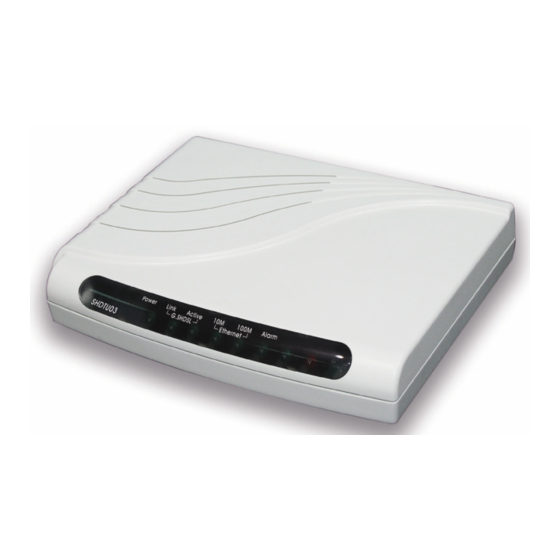
Chapter 1. Introduction 1.4 Front Panel The front panel displays LED status Front Panel of SHDTU03/ET10R Front Panel of SHDTU03/ET10RS LED status of 4-port router LEDs Active Description Power Power adaptor is connected to the router Link SHDSL line connection is established G.SHDSL Active Transmit or received data over SHDSL link... -
Page 15: Rear Panel
Chapter 1. Introduction The rear panel of SHDSL router is where all of the connections are made. Rear Panel of SHDTU03/ET10R router with or without firewall Rear Panel of SHDTU03/ET10RS router with or without firewall CAUTION: To reduce the risk of fire, use only No. 26 AWG or larger telecommunication line cord. - Page 16 Chapter 1. Introduction The reset button can be used in one of two ways. 1. When you want to change the SHDTU03's configuration but you forgot the user name or password, press the Reset Button for three or four seconds with a paper clip or sharp pencil. Pressing the Reset Button in this way will cause the SHDTU03 to load the factory default settings and lose all of your configuration.
-
Page 17: Chapter 2. Configuration
Chapter 2. Configuration This guide is designed to lead users through Web Configuration of SHDTU03/ET10R Router in the easiest and quickest way possible. Please follow the instructions carefully. Note: There are three methods to configure the router: serial console, Telnet and Web Browser. -
Page 18: Determine Connection Setting
Chapter 2. Configuration Step 4: Determine Connection Setting Users need to know the Internet Protocol supplied by your Service Provider and determine the mode of setting. Protocol Selection RFC1483 Bridged Ethernet over ATM RFC1577 Classic Internet Protocol over ATM RFC2364 Point-to-Point Protocol over ATM RFC2516 Point-to-Point Protocol over Ethernet... - Page 19 Chapter 2. Configuration IPoA PPPoA VPI: VPI: VCI: VCI: Encapsulation: Encapsulation: IP Address: User Name: Subnet Mask: Password: Gateway: DNS Server: DNS Server: Host Name: (if applicable) Host Name: (if applicable) IP Address: (if applicable) PPPoE VPI: VCI: Encapsulation: User Name: Password: DNS Server: Host Name:...
-
Page 20: Install The Shdsl Router
Chapter 2. Configuration Step 5: Install the SHDSL Router Caution: To avoid possible damage to this Router, do not turn on the router before Hardware Installation. Connect the power adapter to the port labeled DC-IN on the rear panel of the product. Connect the Ethernet cable. - Page 21 Chapter 2. Configuration...
-
Page 22: 2.2 Configuration Via Web Browser
Chapter 2. Configuration Server Storage Wireless Server Wireless Access Point Note Book Workstation Switching Mobile Device Laser Printer Power Adapter Wall Jack G.shdsl RJ-11 DB-9 Cable 4-port router with complex network topology 2.2 Configuration via Web Browser For Win85, 98 and Me, click the start button. Select setting and control panel. - Page 23 Chapter 2. Configuration In the Configuration window, select the TCP/IP protocol line that has been associated with your network card and then click the properties button. Choose the IP Address tab. Select Obtain an IP address automatically. Click the OK button.
- Page 24 Chapter 2. Configuration The window will ask you to restart the PC. Click the Yes button. When the PC has restarted, Open Internet Explorer or Netscape Browser to connect to the Router. Type http://192.168.0.1 The default IP address and sub net- mask of the Router is 192.168.0.1 and 255.255.255.0.
-
Page 25: Chapter 3. Set Up
Chapter 3. Set-Up 3.1 Basic (Quick Setup) The Basic Setup contains Bridge and Route operation modes. Follow this example to set Bridge mode Click Basic for basic installation. Bridge Mode Bridge IP: 192.168.0.1 IP: 192.168.0.254 Netmask: 255.255.255.0 Gateway: 192.168.0.254 DSLAM IP: 192.168.0.2 VPI:0, VCI:32 Netmask: 255.255.255.0... -
Page 26: Routing Mode
Chapter 3. Set-Up The screen will prompt with the new configuration parameters. Check the parameters and Click Restart The router will reboot with the new settings or Continue to configure other parameters. Routing Mode Routing mode contains settings for DHCP server, Point-to-Point Protocol over ATM and Ethernet, IP over ATM and Ethernet over ATM. -
Page 27: Dhcp Server
Chapter 3. Set-Up DHCP Server Dynamic Host Configuration Protocol (DHCP) is a TCP/IP Suite protocol that allows network administrators to manage and automate centrally the assignment of Internet Protocol (IP) addresses in an organization's network. Using the Internet Protocol, each machine that wishes to connect to the Internet needs a unique IP address. -
Page 28: Pppoe Or Pppoa
Chapter 3. Set-Up PPPoE or PPPoA PPPoA (point-to-point protocol over ATM) and PPPoE (point-to-point protocol over Ethernet) are authentication and connection protocols used by many service providers for broadband Internet access. These are specifications for connecting multiple computer users on an Ethernet local area network to a remote site through common customer premises equipment, which is the telephone company's term for a customer's modem or similar devices. - Page 29 Chapter 3. Set-Up Type the ISP1 parameters. ?Username and password are provided by your ISP. Username: test Password: test Password Confirm: test Idle Time: 10 Click Next. ?For security, the password will be displayed with star symbols. The screen will prompt with the parameters to be written in Flash. Check the parameters before writing to Flash.
- Page 30 Chapter 3. Set-Up IPoA or EoA IP: 10.1.2.1 Router Netmask: 255.255.255.0 Gateway: 10.1.2.2 IP: 192.168.0.1 DNS: 168.95.1.1 Netmask: 255.255.255.0 IP: 10.1.2.2 Netmask: 255.255.255.0 DSLAM IP: 192.168.0.2~51 VPI:0, VCI:33 Netmask: 255.255.255.0 Encapsulation: LLC Gateway: 192.168.0.1 Type the Wan Parameters; VPI: 0 VCI: 33 AAL5 Encap: LLC Protocol: IPoA , EoA , IPoA + NAT or...
-
Page 31: 3.2 Advanced Set-Up
Chapter 3. Set-Up 3.2 Advanced Set-Up Advanced setup contains the configuration steps for SHDSL, WAN, Bridge, Route, NAT/DMZ, Virtual server and firewall parameters. SHDSL You can setup the Annex type, data rate and SNR margin for SHDSL parameters in SHDSL. Click SHDSL Annex Type: There are two Annex types supported, Annex A and Annex B, in... -
Page 32: Wan
Chapter 3. Set-Up The SHDSL router supports up to 8 PVCs. The parameters are setup under WAN. The WAN Number 1 will be the parameters setup in Basic Setup. If you want to setup another PVC, you may configure them in WAN 2 to WAN 8. -
Page 33: Bridge
Chapter 3. Set-Up Bridge The bridge mode can be setup with static bridge parameters. Click Bridge to setup. Press Add to add the static bridge information. The screen will prompt with the parameters that will be written to Flash. Check the parameters before writing to Flash. -
Page 34: Vlan
Chapter 3. Set-Up VLAN Virtual LAN (VLAN) is defined as a group of devices on one or more LANs that are configured so that they can communicate as if they were attached to the same wire, when in fact they are located on a number of different LAN segments. - Page 35 Chapter 3. Set-Up Click VLAN to configure VLAN. The SHDTU03 supports two types of VLAN, 802.1Q and Port-Based. The user can configure either one of them in the router. For setting 802.1Q VLAN click the 802.1Q Tag-Based VLAN. The screem will prompt as follows.
- Page 36 Chapter 3. Set-Up If the SHDTU03 works in bridge mode, the Link type of WAN will be Trunk, tagged port, and you can assign any PVID to WAN except 0 and leaving blank. When the SHDTU03 works under routing mode, the Link Type of WAN will be Access mode, un-tagged port.
-
Page 37: Route
Chapter 3. Set-Up LAN1 LAN2 LAN3 LAN4 Group 1 Group 2 Group 3 No LAN1 LAN2 LAN3 LAN4 Route If the Router is connected to more than one network, it may be necessary to set up a static route between them. A static route is a pre- determined pathway that network information must travel to reach a specific host or network. - Page 38 Chapter 3. Set-Up Click Route to modify the routing information. To modify the RIP (Routing information protocol) Parameters: RIP Mode: Enable Auto RIP Summary: Enable Press Modify RIP Mode: this parameter determines how the product handles RIP (Routing information protocol). RIP allows it to exchange routing information with other routers.
- Page 39 Chapter 3. Set-Up RIP Version: This determines the format and broadcasting method of any RIP transmissions by the gateway. RIP v1: it only sends RIP v1 messages only. RIP v2: it send RIP v2 messages in multicast and broadcast format. Authentication required.
-
Page 40: Nat/Dmz
Chapter 3. Set-Up NAT/DMZ NAT (Network Address Translation) is the translation of an Internet Protocol address (IP address) used within one network to a different IP address known within another network. One network is designated as the inside network (private) and the other as the outside network (public). - Page 41 Chapter 3. Set-Up If you want to enable the NAT/DMZ functions, click Enable. Enable the DMZ host Function will use the IP address assigned to the WAN for enabling DMZ function for the virtual IP address. Multi-DMZ: Some users who have two or more global IP addresses assigned by ISP can use the multi DMZ function.
-
Page 42: Virtual Server
Chapter 3. Set-Up Virtual Server For example: Specific ports on the WAN interface are re-mapped to services inside the LAN. As an example, only 69.210.1.8 (e.g., assigned to WAN from ISP) is visible to the Internet, but does not actually have any services (other than NAT of course) running on gateway. -
Page 43: Chapter 4. Administration
Chapter 4. Administration This session introduces security, simple network management protocol (SNMP) and time synchronization. Security For system security, it is suggested to change the default user name and password after the first setup, otherwise unauthorized persons may gain access to the router and change the parameters. There are three ways to configure the router, Web browser, Telnet and serial console. -
Page 44: Snmp
Chapter 4. Administration SNMP Simple Network Management Protocol (SNMP) is the protocol not only governing network management, but also for the monitoring of network devices and their functions. The router can generate SNMP traps to indicate alarm conditions, and it relies on SNMP community strings to implement SNMP security. - Page 45 Chapter 4. Administration SNMP status: Enable Access Right: Deny for deny all access Access Right: Read for access read only Access Right: Write for access read and write. Community: it serves as password for access right. After configuring the community pool, press OK.
-
Page 46: Time Sync
Chapter 4. Administration Time Sync Time synchronization is an essential element for any business that relies on an IT system. The reason for this is that these systems all have clocks that are the source of time for files or operations they handle. Without time synchronization, time on these systems varies with each other or with the correct time and this can cause, firewall packet filtering schedule processes to fail, security to be compromised, or system log exposures with wrong... -
Page 47: Chapter 5. Utility
Chapter 5. Utility This section describes the utility to display the system information, load the factory default configuration, upgrade the firmware and restart the gateway. System Info Click System Info to review the system information. The browser will prompt for the system information. Config Tool This configuration tool has three functions: load Factory Default, Restore Configuration and Backup Configuration. -
Page 48: Upgrade
Chapter 5. Utility Upgrade You can upgrade the gateway using the upgrade function. Press Upgrade. Browse to the file and press the OK button to upgrade. The system will reboot automatically after finishing. Do not allow any power disruption during the upgrade process. -
Page 49: Restart
Chapter 5. Utility Restart For restarting the router, click the Restart item under UTILITY. Press Restart to reboot the router. - Page 50 Chapter 5. Utility This page was left blank intentionally.
-
Page 51: Chapter 6. Status
Chapter 6. Status You can monitor the SHDSL status including mode, Tx power and Bitrate and Performance information including SNR margin, attenuation and CRC error count. LAN status will display the MAC address, IP address, Subnet mask and DHCP client table. WAN status will display the WAN interface information. - Page 52 Chapter 6. Status CO side Click Bridge and CO Side to setup Bridging mode of the Router and then click Next. LAN Parameters Enter IP: 192.168.0.1 Enter Subnet Mask: 255.255.255.0 Enter Gateway: 192.168.0.1 Enter Host Name: SOHO WAN1 Parameters Enter VPI: 0 Enter VCI: 32 Click LLC Click Next...
- Page 53 Chapter 6. Status CPE Side Click Bridge and CPE Side to setup Bridging mode of the Router and then click Next. LAN Parameters Enter IP: 192.168.0.2 Enter Subnet Mask: 255.255.255.0 Enter Gateway: 192.168.0.2 Enter Host Name: SOHO WAN1 Parameters Enter VPI: 0 Enter VCI: 32 Click LLC Click Next...
- Page 54 Chapter 6. Status LAN-to-LAN connection in routing mode STU-C (CO) STU-R (CPE) Router Router IP: 192.168.20.1 IP: 192.168.10.1 IPoA or EoA Netmask: 255.255.255.0 Netmask: 255.255.255.0 VPI:0, VCI:32 Encapsulation: LLC IP: 192.168.30.1 IP: 192.168.30.2 Netmask: 255.255.255.0 Netmask: 255.255.255.0 Gateway: 192.168.30.2 Gateway: 192.168.30.1 IP: 192.168.20.100 IP: 192.168.10.200 Netmask: 255.255.255.0...
- Page 55 Chapter 6. Status Type the Wan Parameters; VPI: 0 VCI: 32 AAL5 Encap: LLC Protocol: IPoA , EoA , IPoA + NAT or EoA + NAT Note: The Protocol used in CO and CPE have to be the same. Click Next to setup the IP parameters.
- Page 56 Chapter 6. Status CPE side Click ROUTE and CPE Side then press Next. Type LAN parameters: IP Address: 192.168.10.1 Subnet Mask: 255.255.255.0 Host Name: SOHO DHCP Service: For more DHCP service, review DHCP Service. Type the Wan Parameters; VPI: 0 VCI: 32 AAL5 Encap: LLC Protocol: IPoA , EoA , IPoA + NAT or...
-
Page 57: Serial
Chapter 7. Serial Console or Telnet Mode Serial Console Check the connectivity of the RS-232 cable from your computer to the serial port of the ROUTER. Start your terminal access program with VT100 terminal emulation. Configure the serial link with baudrate of 9600, 8 data bits, no parity check, 1 stop bit, and no flow-control, and press the SPACE key until the login screen appears. -
Page 58: Window Structure
Chapter 7. Serial Console or Telnet Mode Window structure From top to bottom, the window will be divided into four parts: Product name Menu field: Menu selection items are prompted on this field. The “ >>” symbol indicates the cursor position. Configuration field: You will configure the parameters in this field. -
Page 59: Menu Driven Interface Commands
Chapter 7. Serial Console or Telnet Mode Menu Driven Interface Commands Before changing the configuration, familiarize yourself with the navigation keys listed in the following table. The operation list will be shown on the window. Keystroke Description [UP] or I Move to field above in the same level menu. -
Page 60: Menu Tree
Chapter 7. Serial Console or Telnet Mode Menu Tree All of the configuration commands that are placed in the subdirectories of Enable are protected by supervisor password. User Name Enable Enable & Password Setup Mode <more...> SHDSL <more...> <more...> Bridge <more...>... - Page 61 Chapter 7. Serial Console or Telnet Mode Setup Mode SHDSL Mode n*64 Type Clear Margin Protocol Address VPI_VCI Encap Class List Bridge Gateway Static LAN_Port Delete WAN1_Port Modify List WAN8_Port Route Static Delete List Generic Attrib Version Authetication Attrib Version Address Authetication Attrib...
- Page 62 Chapter 7. Serial Console or Telnet Mode Setup Mode <more...> SHDSL <more...> <more...> Bridge <more...> Route <more...> Range IP-share Virtual Delete List Global Range Interface Delete List Fixed Modify Interface Delete List Clear Modify Interface Port List Server Protocol Name Begin Active Address...
- Page 63 Chapter 7. Serial Console or Telnet Mode Admin User Clear Modify Attrib Profile List Security Port IP_pool Modify Clear List Attrib Edit SNMP List Profile Edit List Passwd SNTP Method Service Time_server1 Time_server2 Time_server3 Update_rate Time_zone List...
- Page 64 Chapter 7. Serial Console or Telnet Mode This page was left blank intentionally.
-
Page 65: Chapter 8. Configuration Commands
Chapter 8. Configuration Commands To setup the router, move the cursor “ >>” to enable and press the enter key. When the screen appears, type the supervisor password. The default supervisor password is root. The password will be written on screen as “ * “ symbol for system security. ---------------------------------------------------------------------- Command: enable <CR>... -
Page 66: Status
Chapter 8. Configuration Commands Status You can view the running system status of SHDSL, WAN, route and interface via the status command. Move cursor “ >> “ to status and press enter. >> shdsl Show SHDSL status Show WAN interface status route Show routing table interface... -
Page 67: Reboot
Chapter 8. Configuration Commands Reboot To reboot the router, use the reboot command. Move the cursor to “ >> “ to reboot and press enter. ----------------------------------------- ----------------------------- Command: reboot <CR> Message: Please input the following information. Do you want to reboot? (y/n): y ---------------------------------------------------------------------- Ping Ping command will be used to test the connection of the router. -
Page 68: User Profile
Chapter 8. Configuration Commands User Profile You can use the user command to clear, modify and list all the user profiles. You can setup up to five users to access the router via console port or Telnet in the user profile table. However users who have the supervisor password can change the configuration of the router. - Page 69 Chapter 8. Configuration Commands Security Security command can be used to configure ten legal IP address for Telnet access and port number. Move the cursor “ >> “ to security and press enter. The default legal address is 0.0.0.0. which means that there is no restriction of IP to access the router via Telnet.
-
Page 70: Supervisor Password And Id
Chapter 8. Configuration Commands 5 SNMP trap entry can be configured in this system. Move the cursor to trap and press enter. ---------------------------------------------------------------------- Command: admin snmp trap <1~5> <more...> Message: Please input the following information. Trap host entry number <1~5> : 2 -------------------------------- -------------------------------------- The screen will prompt as follows: >>... - Page 71 Chapter 8. Configuration Commands To configure SNTP v4 time synchronization, follow the procedures below. move the cursor to method and press enter. ---------------------------------------------------------------------- Command: admin sntp method <SNTPv4|SyncWithPC> Message: Please input the following information. SYNC method (Enter for default) <SyncWithPC> : SNTPv4 ---------------------------------------------------------------------- Move the cursor to service and press enter.
-
Page 72: Utility
Chapter 8. Configuration Commands Move the cursor to time_zone and configure where your router is placed. The easiest way to know the time zone offset hour is from your PC clock. Double click the clock at the right corner of monitor and check the time zone. -
Page 73: Setup
Chapter 8. Configuration Commands Setup All of the setup parameters are located in the subdirectories of setup. Move the cursor “ >> “ to setup and press enter. >> mode Switch system operation mode shdsl Configure SHDSL parameters Configure WAN interface profile bridge Configure transparent bridging vlan... - Page 74 Chapter 8. Configuration Commands SHDSL You can setup the SHDSL parameters by using the command shdsl. Move the cursor “ >> “ to shdsl and press enter. >> mode Configure SHDSL mode n*64 Configure SHDSL data rate type Configure SHDSL annex type clear Clear current CRC error count margin...
- Page 75 Chapter 8. Configuration Commands The router supports 8 PVC, private virtual circuit, and so you can setup eight WANs; WAN1 to WAN8. Move the cursor “ >> “ to wan and press enter. To setup WAN1, type 1. ---------------------------------------------------------------------- Command: setup wan <1~8> Message: Please input the following information.
- Page 76 Chapter 8. Configuration Commands Bridge You can setup the bridge parameters using the bridge command. If the product is configured as a router, you do not need to setup the bridge parameters. Move the cursor “ >> “ to bridge and press enter.
- Page 77 Chapter 8. Configuration Commands VLAN Virtual LAN (VLAN) is defined as a group of devices on one or more LANs that are configured so that they can communicate as if they were attached to the same wire, when in fact they are located on a number of different LAN segments.
- Page 78 Chapter 8. Configuration Commands To activate the VLAN function, move the cursor “ >> “ to mode and press enter. The products support two types of VLAN, 802.11Q and Port-Based. The IEEE 802.1Q defines the operation of VLAN bridges that permit the definition, operation, and administration of VLAN topologies within a bridged LAN infrastructure.
- Page 79 Chapter 8. Configuration Commands To assign PVID (Port VID), move the cursor “ >> ” to PVID and press enter. The port index 1 to 4 represents LAN1 to LAN4 respectively and port index 5 represents WAN. VID value is the group at which you want to assign the PVID of the port.
- Page 80 Chapter 8. Configuration Commands If the Router is connected to more than one network, it may be necessary to set up a static routes between them. A static route is a pre-determined pathway that network information must travel to reach a specific host or network. With Dynamic Routing, you can enable the Router to automatically adjust to physical changes in the network’...
- Page 81 Chapter 8. Configuration Commands The SHDTU03 supports 8 PVCs and you can configure the RIP parameters of each WAN via the wan command. Move the cursor “ >> ” to wan and press enter. ---------------------------------------------------------------------- Command: setup route rip wan <1 ~8> <more...> Message: Please input the following information.
- Page 82 Chapter 8. Configuration Commands NAT (Network Address Translation) is the translation of an Internet Protocol address (IP address) used within one network to a different IP address known within another network. One network is designated the inside (private) network and the other is the outside (public) network. Typically, a company maps its local inside network addresses to one or more global outside IP addresses and reverse the global IP addresses of incoming packets back into local IP addresses.
- Page 83 Chapter 8. Configuration Commands You can delete virtual IP address range- from 1 to 5- by using the delete command. You can view the virtual IP address range via the list command. To setup global IP address pool, move the cursor “>>” to global command and press enter. >>...
- Page 84 Chapter 8. Configuration Commands To modify the fixed IP address mapping, move the cursor “>>” to the fixed command and press enter. >> modify Modify fixed NAT mapping interface Bind address pair to specific interface delete Delete fixed NAT mapping list Show fixed IP address mapping You can create up to 10 fixed NAT mapping entries via the range command.
- Page 85 Chapter 8. Configuration Commands To configure Port Address Translation, move the cursor “>>” to the pat command and press enter. >> clear Clear virtual server mapping modify Modify virtual server mapping list Show virtual server mapping pool You can delete virtual server mapping entries- from 1 to 10- by using the clear command. You can create up to 10 virtual server mapping entries via the modify command.
- Page 86 Chapter 8. Configuration Commands To setup demilitarized zone, move the cursor “>>” to dmz and press enter. >> active Tigger DMZ host function address Configure virtual IP address and interface You can enable the demilitarized zone via the active command. After enabling the DMZ, shift the cursor to address and press enter.
- Page 87 Chapter 8. Configuration Commands To configure the DHCP server, move the cursor to dhcp and press enter. >> generic Configure generic DHCP parameter s fixed Configure fixed host IP address list list Show DHCP configuration The generic DHCP parameters can be configured via the generic command. >>...
-
Page 88: Dns Proxy
Chapter 8. Configuration Commands DNS proxy You can setup three DNS servers in the product. The number 2 and 3 DNS servers are optional. Move the cursor “ >> “ to dns_proxy and press enter. ------------------------------------------ ---------------------------- Command: setup dns_proxy <IP> [IP] [IP] Message: Please input the following information. - Page 90 Transmission Units CTC Union Technologies Co., Ltd. Far Eastern Vienna Building (Neihu Technology Park) 8F, No. 60, ZhouZi St., Nei-Hu, Taipei, Taiwan Phone:(886) 2.2659.1021 Fax:(886) 2.2799.1355 E-mail: info@ctcu.com http://www.ctcu.com...
Need help?
Do you have a question about the SHDTU03-ET10R and is the answer not in the manual?
Questions and answers