Table of Contents
Advertisement
Quick Links
Advertisement
Table of Contents

Related Manuals for CTC Union MSW-4424C Series


Summary of Contents for CTC Union MSW-4424C Series
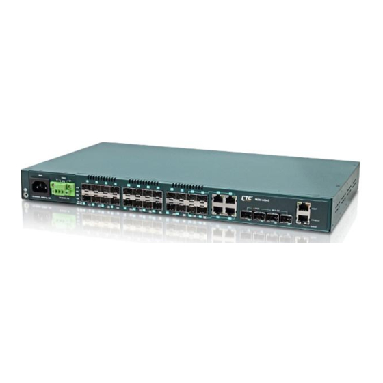
- Page 1 MSW-4424C Series L2+ Gigabit Carrier Ethernet Switch...
- Page 2 CTC Union Technologies makes no warranty, representation, or guarantee regarding the suitability of its products for any particular purpose, nor does CTC Union assume any liability arising out of the application or use of any product and specifically disclaims any and all liability, including without limitation any consequential or incidental damages.
- Page 3 This manual supports the following models: MSW-4424C This document is the current official release manual. Please check CTC Union's website for any updated manual or contact us by E-mail at sales@ctcu.com. Please address any comments for improving this manual or to point out omissions or errors to marketing@ctcu.com.
-
Page 4: Table Of Contents
TABLE OF CONTENTS CHAPTER 1. INTRODUCTION ....................... 9 1.1 P ........................9 RODUCT ESCRIPTION 1.2 P ............................9 ANELS CHAPTER 2. INSTALLATION ....................... 10 2.1 F ........................10 IBER ONNECTIONS 2.2 MGMT P ....................... 10 ONNECTION 2.3 C ......................10 ONSOLE ONNECTION 2.3.1 RJ-45 Pin Assignment ............................ - Page 5 TABLE OF CONTENTS 4.3.4.1.5 HTTPS ..................................36 4.3.4.1.6 Access Management Configuration ........................36 4.3.4.1.7 SNMP ..................................37 4.3.4.1.7.1 SNMP System Configuration ..........................37 4.3.4.1.7.2 SNMP Trap Configuration ..........................38 4.3.4.1.7.3 SNMPv3 Community Configuration ......................41 4.3.4.1.7.4 SNMPv3 User Configuration ..........................41 4.3.4.1.7.5 SNMPv3 Group Configuration ........................42 4.3.4.1.7.6 SNMPv3 View Configuration ..........................43 4.3.4.1.7.7 SNMPv3 Access Configuration ........................43 4.3.4.1.8 RMON ..................................44 4.3.4.1.8.1 RMON Statistics Configuration ........................44...
- Page 6 TABLE OF CONTENTS 4.3.11.2.3 Port Filtering Profile ............................84 4.3.12 LLDP ................................84 4.3.12.1 LLDP Configuration ..............................85 4.3.12.2 LLDP-MED ...................................86 4.3.13 EPS ................................. 88 4.3.14 MEP ................................90 4.3.15 ERPS ................................100 4.3.16 MAC Table ..............................101 4.3.17 VLAN Translation ............................102 4.3.17.1 Port to Group Mapping ............................103 4.3.17.2 VID Translation Mapping ............................103 4.3.18 VLANs ................................
- Page 7 TABLE OF CONTENTS 4.4.2.2 SFP ....................................141 4.4.2.3 Traffic Overview .................................142 4.4.2.4 QoS Statistics ................................143 4.4.2.5 QCL Status ..................................143 4.4.2.6 Ports Detailed Statistics ..............................144 4.4.3 Link OAM ............................... 146 4.4.3.1 Statistics ..................................146 4.4.3.2 Port Status ..................................147 4.4.3.3 Event Status ................................148 4.4.4 DHCP ................................150 4.4.4.1 Server ..................................150 4.4.4.1.1 Statistics ................................150 4.4.4.1.2 Binding ................................151...
- Page 8 TABLE OF CONTENTS 4.4.10.2.2 Groups Information ............................176 4.4.10.2.3 IPv6 SFM Information............................176 4.4.11 LLDP ................................177 4.4.11.1 Neighbors .................................177 4.4.11.2 LLDP-MED Neighbors ..............................177 4.4.11.3 Port Statistics ................................178 4.4.12 Ethernet Services ............................179 4.4.12.1 EVC Statistics ................................179 4.4.12.2 ECE Statistics................................179 4.4.13 MAC Table ..............................180 4.4.14 VLANs ................................
-
Page 9: Chapter 1. Introduction
CHAPTER 1. INTRODUCTION Thank you for purchasing this product from CTC Union. We hope this product is everything you wanted and more. Our Product Managers and R&D team have placed a "quality first" motto in our development of this series of Ethernet switches with the desire of providing a highly stable and reliable product that will give years of trouble-free operation. -
Page 10: Chapter 2. Installation
2.1 Fiber Connections The MSW-4424C Series utilizes SFP modules for fiber transmissions. Each of the fiber ports has an associated status LED to indicate the presence or absence of fiber link and will also flash when there is Ethernet activity on the port. -
Page 11: Pin Assignment
CHAPTER 2 INSTALLATION Figure 5. Console Port Connection 2.3.1 RJ-45 Pin Assignment This RJ-45 connector provides an RS-232 DCE (data communication equipment) asynchronous serial connection for local management. Ref. Definition Direction Receive Data Out towards DTE Transmit Data In from DTE Signal Ground CONSOLE 2.3.2 Accessory Cable... -
Page 12: Rack Mounting
CHAPTER 2 INSTALLATION 2.5 Rack Mounting When installing the rack mount brackets, be sure to correctly align the orientation pin. Use the screws provided in the rack-mounting kit to securely fasten the brackets. Figure 8. Attaching Rack-Mounting Brackets Figure 9. The Switch with Rack-Mounting Brackets Figure 10. -
Page 13: Led Indicators & Reset To Default Button
CHAPTER 2 INSTALLATION 2.6 LED Indicators & Reset to Default Button Color Status Meaning Green The switch is active. Alert The switch does not receive power. Power 1 module is working. PWR 1 Green Power 1 module is off. Power 2 module is working. PWR 2 Green Power 2 module is off. -
Page 14: Chapter 3. Introduction To Cli
The first and very basic is serial console access. This method is also called out-of-band management and is only available when a terminal or administrator PC can be physically connected to the local MSW-4424C Series switch at the CONSOLE port using RJ45 to RS-232 console cable. Accessing the switch via CONSOLE port allows the user to use CLI (Command Line Interface) to manage and configure the device. -
Page 15: Cli Online Help
CHAPTER 3 INTRODUCTION TO CLI 3.2.1 CLI Online Help While using the CLI, online help is always available by using 'help' command or typing '?' (question mark). Commands can be recalled by using the 'up/down arrow keys'. clear Reset functions configure Enter configuration mode copy... -
Page 16: Default Gateway
CHAPTER 3 INTRODUCTION TO CLI 3.2.2.2 Default Gateway Syntax: ip route <v_ipv4_addr> <v_ipv4_netmask> <v_ipv4_gw> # config t (config)# ip route 10.1.2.0 255.255.255.0 10.1.1.254 (Config)# Note: The <v_ip_netmask> parameter must include the subnet mask class. A default gateway would use '0'. In this example the <v_ip_gw>... -
Page 17: Reboot Device
CHAPTER 3 INTRODUCTION TO CLI 3.2.4 Reboot Device Syntax: # reload cold 3.2.5 Admin Password Syntax: username <username> privilege <priv> password unencrypted <password> # config t (config)# username admin privilege 15 password unencrypted secret (config)# Note: To set the password "secret" for the admin user. (Admin user has highest privilege level of 15.) Syntax: username <username>... -
Page 18: Chapter 4. Web Operation & Configuration
CHAPTER 4. WEB OPERATION & CONFIGURATION MSW-4424C series provides a wide range of basic and advanced management functions that can help network engineers to design and implement their own network. The user can manage MSW-4424C via the console port or using Web interface. -
Page 19: Icons & Buttons
CHAPTER 4 Chapter 4. Web Configuration & Operation WEB OPERATION & CONFIGURATION 4.2 Icons & Buttons This switch provides some basic and frequently-used functions as icons on the top of Web management page. You can use these icons for a quick help or logout. 4.2.1 Port Status The initial page, when logged in, displays a graphical overview of the port status for all optical ports. -
Page 20: Configuration
CHAPTER 4 Chapter 4. Web Configuration & Operation WEB OPERATION & CONFIGURATION For the remainder of this section, each menu item will be explained one by one, in order as they descend down the menu screen, starting with the "System" menu. 4.3 Configuration This section offers explanations for both basic and advanced management functions available in MSW-4424C. -
Page 21: System Ip
CHAPTER 4 Chapter 4. Web Configuration & Operation WEB OPERATION & CONFIGURATION 4.3.1.2 System IP Setup the IP configuration, interface and routes. IP Configuration Mode: The "Mode" pull-down configures whether the IP stack should act as a Host or a Router. In Host mode, IP traffic between interfaces will not be routed. -
Page 22: System Ntp
CHAPTER 4 Chapter 4. Web Configuration & Operation WEB OPERATION & CONFIGURATION IPv4 Mask: The IPv4 network mask is entered by a number of bits (prefix length). Valid values are between 0 and 30 bits for a IPv4 address. If DHCP is enabled, this field is not used. The field may also be left blank if IPv4 operation on the interface is not desired. -
Page 23: System Time
CHAPTER 4 Chapter 4. Web Configuration & Operation WEB OPERATION & CONFIGURATION symbol '::' is a special syntax that can be used as a shorthand way of representing multiple 16-bit groups of contiguous zeros; but it can appear only once. NTP servers can also be represented by a legally valid IPv4 address. For example, '::192.1.2.34'. -
Page 24: System Log Configuration
CHAPTER 4 Chapter 4. Web Configuration & Operation WEB OPERATION & CONFIGURATION End time settings: Select he ending week, day, month, year, hours, and minutes. Offset settings: Enter the number of minutes to add during Daylight Saving Time. The allowed range is 1 to 1440. 4.3.1.5 System Log Configuration Configure System Log on this page. - Page 25 CHAPTER 4 Chapter 4. Web Configuration & Operation WEB OPERATION & CONFIGURATION Port: This device is a L2 carrier Ethernet access switch with 20 SFP ports (numbered 1 to 20), 4 combo ports (numbered 21~24) and 4 SFP-based uplink ports (numbered 25~28). Each logical port number is displayed in a row. The select all "*"...
-
Page 26: Dhcp
CHAPTER 4 Chapter 4. Web Configuration & Operation WEB OPERATION & CONFIGURATION 100Mbps FDX: Forces the port to 100Mbps full duplex mode. 1Gbps FDX: Forces the port to 1Gbps full duplex mode. 10Gbps FDX: Forces the fiber port to 10Gbps full duplex mode. Auto Media Select (AMS) is used for dual media ports (ports supporting both copper and fiber SFP cables). -
Page 27: Server
CHAPTER 4 Chapter 4. Web Configuration & Operation WEB OPERATION & CONFIGURATION 4.3.3.1 Server 4.3.3.1.1 Mode Global Mode Mode: Enable or disable DHCP server mode. When enabled, this device can act as a DHCP server and provide IP address to clients that request for one. VLAN Mode Click “Add VLAN Range”... -
Page 28: Pool
CHAPTER 4 Chapter 4. Web Configuration & Operation WEB OPERATION & CONFIGURATION IP Range: Enter the starting and ending IP address that are not allocated to DHCP clients. The starting IP address must be smaller or equal to the ending IP address. If there is only one excluded IP address, it can be entered either in starting or ending IP address field. - Page 29 CHAPTER 4 Chapter 4. Web Configuration & Operation WEB OPERATION & CONFIGURATION Pool Name: Select the pool name that you want to configure from the pull-down menu. Setting Pool Name: Display the pool name for this configured entry. Type: Select the pool type. Network: The pool defines a pool of IP addresses to service more than one DHCP client.
-
Page 30: Dhcp Snooping
CHAPTER 4 Chapter 4. Web Configuration & Operation WEB OPERATION & CONFIGURATION 4.3.3.2 DHCP Snooping DHCP Snooping allows the switch to protect a network from being attacked by other devices or rogue DHCP servers. When DHCP Snooping is enabled on the switch, it can filter IP traffic on insecure (untrusted) ports that the source addresses cannot be identified by DHCP Snooping. -
Page 31: Relay Configuration
CHAPTER 4 Chapter 4. Web Configuration & Operation WEB OPERATION & CONFIGURATION Untrusted: Host ports (connecting to customer devices) are treated as Untrusted sources. DHCP Snooping filters out invalid DHCP messages from Untrusted sources. 4.3.3.3 Relay Configuration Relay Mode: Enable or disable the DHCP relay function. Relay Server: Enter DHCP server IP address that is used by the switch’s DHCP relay agent. -
Page 32: Security
CHAPTER 4 Chapter 4. Web Configuration & Operation WEB OPERATION & CONFIGURATION 4.3.4 Security Under the security heading are three major icons, switch, network and AAA. 4.3.4.1 Switch 4.3.4.1.1 Users This page provides an overview of the current users. Currently the only way to login as another user on the web server is to close and reopen the browser. -
Page 33: Privilege Levels
CHAPTER 4 Chapter 4. Web Configuration & Operation WEB OPERATION & CONFIGURATION Add User User Name: Enter the new user name. Password: Enter the password for this user account. Password (again): Retype the password for this user account. Privilege Level: Select the appropriate privilege level for this user account. The allowed range is 1 to 15. If the privilege level value is 15, it can access all groups, i.e. -
Page 34: Auth Method
CHAPTER 4 Chapter 4. Web Configuration & Operation WEB OPERATION & CONFIGURATION Group Name: This name identifies the privilege group. In most cases, a privilege level group consists of a single module (e.g. LACP, RSTP or QoS), but a few of them contains more than one. The following description defines these privilege level groups in details: System: Contact, Name, Location, Timezone, Daylight Saving Time, Log. -
Page 35: Ssh
CHAPTER 4 Chapter 4. Web Configuration & Operation WEB OPERATION & CONFIGURATION Client: The management client for which the configuration below applies. Methods: Method can be set to one of the following values: no: Authentication is disabled and login is not possible. local: Use the local user database on the switch for authentication. -
Page 36: Https
CHAPTER 4 Chapter 4. Web Configuration & Operation WEB OPERATION & CONFIGURATION 4.3.4.1.5 HTTPS Configure HTTPS on this page. Mode: Indicates the HTTPS operation mode. When the current connection is HTTPS and HTTPS mode operation is disabled, web browser will automatically redirect to an HTTP connection. Possible modes are: Enabled: Enable HTTPS mode operation. -
Page 37: Snmp
CHAPTER 4 Chapter 4. Web Configuration & Operation WEB OPERATION & CONFIGURATION HTTP/HTTPS: Checked indicates that the matched host can access the switch from HTTP/HTTPS interface. SNMP: Checked indicates that the matched host can access the switch from SNMP. TELNET/SSH: Indicates that the matched host can access the switch from TELNET/SSH interface. Click the “Delete”... -
Page 38: Snmp Trap Configuration
CHAPTER 4 Chapter 4. Web Configuration & Operation WEB OPERATION & CONFIGURATION Engine ID: Indicates the SNMPv3 engine ID. The string must contain an even number (in hexadecimal format) with number of digits between 10 and 64, but all-zeros and all-'F's are not allowed. Changes to the Engine ID will clear all original local users. - Page 39 CHAPTER 4 Chapter 4. Web Configuration & Operation WEB OPERATION & CONFIGURATION Disabled: Disable SNMP trap mode operation. Trap Version: Indicates the SNMP trap supported version. Possible versions are: SNMP v1: Set SNMP trap supported version 1. SNMP v2c: Set SNMP trap supported version 2c. SNMP v3: Set SNMP trap supported version 3.
- Page 40 CHAPTER 4 Chapter 4. Web Configuration & Operation WEB OPERATION & CONFIGURATION System: The system trap events include the following. Warm Start: The switch has been rebooted from an already powered on state. Cold Start: The switch has booted from a powered off or due to power cycling (power failure). AAA: Authentication, Authorization and Accounting;...
-
Page 41: Snmpv3 Community Configuration
CHAPTER 4 Chapter 4. Web Configuration & Operation WEB OPERATION & CONFIGURATION After completing all the trap settings, click the "Save" button. 4.3.4.1.7.3 SNMPv3 Community Configuration Configure SNMPv3 community table on this page. The entry index key is Community. Delete: Check to delete the entry. It will be deleted during the next save. Community: Indicates the community access string to permit access to SNMPv3 agent. -
Page 42: Snmpv3 Group Configuration
CHAPTER 4 Chapter 4. Web Configuration & Operation WEB OPERATION & CONFIGURATION The value of security level cannot be modified if entry already exists. That means it must first be ensured that the value is set correctly. Authentication Protocol: Indicates the authentication protocol that this entry should belong to. Possible authentication protocols are: None: No authentication protocol. -
Page 43: Snmpv3 View Configuration
CHAPTER 4 Chapter 4. Web Configuration & Operation WEB OPERATION & CONFIGURATION v1: Reserved for SNMPv1. v2c: Reserved for SNMPv2c. usm: User-based Security Model (USM) for SNMPv3. Security Name: A string identifying the security name that this entry should belong to. The allowed string length is 1 to 32, and the allowed content is ASCII characters from 0x21 to 0x7E. -
Page 44: Rmon
CHAPTER 4 Chapter 4. Web Configuration & Operation WEB OPERATION & CONFIGURATION any: Any security model accepted(v1|v2c|usm). v1: Reserved for SNMPv1. v2c: Reserved for SNMPv2c. usm: User-based Security Model (USM) for SNMPv3. Security Level: Indicates the security level that this entry should belong to. Possible security models are: NoAuth, NoPriv: No authentication and no privacy. -
Page 45: Rmon Alarm Configuration
CHAPTER 4 Chapter 4. Web Configuration & Operation WEB OPERATION & CONFIGURATION Data Source: Indicates the port ID which wants to be monitored. Interval: Indicates the polling interval. By default, 1800 seconds is specified. The allowed range is 1 - 3600 seconds. Buckets: The number of buckets requested for this entry. -
Page 46: Rmon Event Configuration
CHAPTER 4 Chapter 4. Web Configuration & Operation WEB OPERATION & CONFIGURATION Falling: Trigger alarm when the first value is less than the falling threshold. Rising Threshold: If the current value is greater than the rising threshold and the last sample value is less than this threshold, then an alarm will be triggered. -
Page 47: Network
CHAPTER 4 Chapter 4. Web Configuration & Operation WEB OPERATION & CONFIGURATION Event Last Time: The value of sysUpTime when an event was last generated for this entry. 4.3.4.2 Network Port Security Limit Control can restrict the number of users that can access the switch based on users’ MAC address and VLAN ID on a per port basis. -
Page 48: Nas
CHAPTER 4 Chapter 4. Web Configuration & Operation WEB OPERATION & CONFIGURATION None: Do not allow more than the specified limit of MAC addresses to access on a port. No action is further taken. Trap: If Limit + 1 MAC addresses are seen on the port, send an SNMP trap. If Aging is disabled, only one SNMP trap will be sent, but with Aging enabled, new SNMP traps will be sent every time the limit is exceeded. - Page 49 CHAPTER 4 Chapter 4. Web Configuration & Operation WEB OPERATION & CONFIGURATION System Configuration Mode: Enable 802.1X and MAC-based authentication globally on the switch. If globally disabled, all ports are allowed to forward frames. Reauthentication Enabled: Select the checkbox to set clients to be re-authenticated after an interval set in "Reauthentication Period"...
- Page 50 CHAPTER 4 Chapter 4. Web Configuration & Operation WEB OPERATION & CONFIGURATION Guest VLAN ID: This VLAN ID is functional only when Guest VLAN is enabled. This is the value that a port’s Port VLAN ID is set to if a port is moved into the Guest VLAN. The range is 1–4095. Max.
-
Page 51: Acl
CHAPTER 4 Chapter 4. Web Configuration & Operation WEB OPERATION & CONFIGURATION Globally Disabled: 802.1X and MAC-based authentication are globally disabled. Link Down: 802.1X and MAC-based authentication are enabled but there is no link on a port. Authorized: The port is forced in authorized mode and the supplicant is successfully authorized. Unauthorized: The port is forced in unauthorized mode and the supplicant is not successfully authorized by the RADIUS server. -
Page 52: Rate Limiters
CHAPTER 4 Chapter 4. Web Configuration & Operation WEB OPERATION & CONFIGURATION Action: Permit or deny a frame based on whether it matches a rule defined in the assigned policy. Rate Limiter ID: Select a rate limiter ID to apply to a port. Rate Limiter rule can be set up in “Rate Limiters” configuration page. -
Page 53: Access Control List
CHAPTER 4 Chapter 4. Web Configuration & Operation WEB OPERATION & CONFIGURATION 4.3.4.2.3.3 Access Control List Access Control List is to establish filtering rules for an ACL policy, for a particular port or for all ports. Rules applied to a port take effect immediately. - Page 54 CHAPTER 4 Chapter 4. Web Configuration & Operation WEB OPERATION & CONFIGURATION Action: Select the action type, either to permit or deny. Rate Limiter: Enable or disable the rate limiter when matched frames are found. Logging: Enable or disable logging when a frame is matched. Shutdown: Enable or disable shutdown a port when a frame is matched.
- Page 55 CHAPTER 4 Chapter 4. Web Configuration & Operation WEB OPERATION & CONFIGURATION ARP Parameter Select “ARP” frame type, then Ethernet Type parameters appear. ARP/RARP: Specify the type of ARP packet. Any: No ARP/RARP opcode flag is specified ARP: The frame must have ARP/RARP opcode set to ARP, RARP: The frame must have ARP/RARP opcode set to RARP Other: The frame has unknown ARP/RARP opcode flag Request/Reply: Specify whether the packet is an ARP request, reply, or either type.
- Page 56 CHAPTER 4 Chapter 4. Web Configuration & Operation WEB OPERATION & CONFIGURATION field is equal to IPv4 (0x4). Select “Any” to indicate a match and not a match. IP: Select “0” to indicate that Protocol Address Space field in ARP/RARP frame is not equal to IP (0x800). Select “1” to indicate that Protocol Address Space is equal to IP (0x800).
-
Page 57: Ip Source Guard
CHAPTER 4 Chapter 4. Web Configuration & Operation WEB OPERATION & CONFIGURATION IPv6 Parameters Next Header Filter: Select next header filter option. Available options include ICMP, UDP, TCP, Other. SIP Filter: Select a source IP filter. “Any” denotes that any SIP filter is allowed. Select “Specific” to enter self-define SIP filter. -
Page 58: Static Table
CHAPTER 4 Chapter 4. Web Configuration & Operation WEB OPERATION & CONFIGURATION Mode: Enable or disable IP source guard on a port. Please note that to make IP source guard work, both global mode and port mode must be enabled. Max Dynamic Clients: Select the maximum number of dynamic clients that can be learned on a port. -
Page 59: Arp Inspection
CHAPTER 4 Chapter 4. Web Configuration & Operation WEB OPERATION & CONFIGURATION 4.3.4.2.5 ARP inspection 4.3.4.2.5.1 Port Configuration ARP Inspection Configuration Mode: Enable or disable ARP inspection function globally. Port Mode Configuration Port: The port number. “Port *” rules apply to all ports. Mode: Enable or disable ARP Inspection on a port. -
Page 60: Vlan Configuration
CHAPTER 4 Chapter 4. Web Configuration & Operation WEB OPERATION & CONFIGURATION 4.3.4.2.5.2 VLAN Configuration VLAN ID: Specify ARP Inspection is enabled on which VLANs. First, you have to enable the port setting on Port mode configuration web page. Only when both Global Mode and Port Mode on a given port are enabled, ARP Inspection is enabled on this given port. -
Page 61: Dynamic Table Configuration
CHAPTER 4 Chapter 4. Web Configuration & Operation WEB OPERATION & CONFIGURATION Click the “Save” button to save newly-configured settings or changes. Click the “Reset” button to restore settings to default settings or previously configured settings. 4.3.4.2.5.4 Dynamic Table Configuration Port: The port number of this entry. -
Page 62: Tacacs
CHAPTER 4 Chapter 4. Web Configuration & Operation WEB OPERATION & CONFIGURATION Deadtime: Deadtime is the period during which the switch will not send new requests to a server that has failed to respond to a previous request. This will stop the switch from continually trying to contact a server that it has already determined as dead. -
Page 63: Aggregation
CHAPTER 4 Chapter 4. Web Configuration & Operation WEB OPERATION & CONFIGURATION Global Configuration Timeout: The time the switch waits for a reply from a TACACS+ server before it retransmits the request. Deadtime: Deadtime is the period during which the switch will not send new requests to a server that has failed to respond to a previous request. -
Page 64: Static
CHAPTER 4 Chapter 4. Web Configuration & Operation WEB OPERATION & CONFIGURATION 4.3.5.1 Static Aggregation Mode Configuration Source MAC Address: All traffic from the same Source MAC address is output on the same link in a trunk. Destination MAC Address: All traffic with the same Destination MAC address is output on the same link in a trunk. IP Address: All traffic with the same source and destination IP address is output on the same link in a trunk. -
Page 65: Lacp
CHAPTER 4 Chapter 4. Web Configuration & Operation WEB OPERATION & CONFIGURATION 4.3.5.2 LACP The Switch supports dynamic Link Aggregation Control Protocol (LACP) which is specified in IEEE 802.3ad. Static trunks have to be manually configured at both ends of the link. In other words, LACP configured ports can automatically negotiate a trunked link with LACP configured ports on another devices. -
Page 66: Link Oam
CHAPTER 4 Chapter 4. Web Configuration & Operation WEB OPERATION & CONFIGURATION 4.3.6 Link OAM The Ethernet Operation, Administration, and Maintenance (OAM; IEEE 802.3ah) protocol for monitoring, and troubleshooting Metro Ethernet networks and Ethernet WANs relies on an optional sub-layer in the data link layer of the Normal link operation. -
Page 67: Event Settings
CHAPTER 4 Chapter 4. Web Configuration & Operation WEB OPERATION & CONFIGURATION Loopback Support: Select the checkbox to enable loopback support on a port. Link OAM remote loopback support can be used for fault localization and link performance testing. Enabling the loopback support will allow the DTE to execute the remote loopback command that helps in the fault detection. -
Page 68: Loop Protection
CHAPTER 4 Chapter 4. Web Configuration & Operation WEB OPERATION & CONFIGURATION Error Threshold: Specify the error threshold value for the window period for the appropriate Link event so as to notify the peer of this error. 4.3.7 Loop Protection Loops sometimes occur in a network due to improper connecting, hardware problem or faulty protocol settings. -
Page 69: Spanning Tree
CHAPTER 4 Chapter 4. Web Configuration & Operation WEB OPERATION & CONFIGURATION Shutdown Port: A loop-detected port is shutdown for a period of time configured in “Shutdown Time”. Shutdown Port and Log: A loop-detected port is shutdown for a period of time configured in “Shutdown Time” and the event is logged. -
Page 70: Bridge Settings
CHAPTER 4 Chapter 4. Web Configuration & Operation WEB OPERATION & CONFIGURATION 4.3.8.1 Bridge Settings Basic Settings Protocol Version: Select the appropriate spanning tree protocol. Protocol versions provided include “STP”, “RSTP”, and “MSTP”. Bridge Priority: Each switch has a relative priority and cost that is used to decide what the shortest path is to forward a packet. -
Page 71: Msti Mapping
CHAPTER 4 Chapter 4. Web Configuration & Operation WEB OPERATION & CONFIGURATION BPDU Guard is therefore used to prevent the device from suffering malicious attacks. With this function enabled, when edge ports receive configuration BPDUs, STP disables those affected edge ports. After a period of recovery time, those disabled ports are re-activated. -
Page 72: Msti Priorities
CHAPTER 4 Chapter 4. Web Configuration & Operation WEB OPERATION & CONFIGURATION 4.3.8.3 MSTI Priorities MSTI: Display MSTI instance number. “MSTI *” priority rule applies to all ports. Priority: Select an appropriate priority for each MSTI instance. Bridge priority is used in selecting the root device, root port, and designated port. -
Page 73: Msti Ports
CHAPTER 4 Chapter 4. Web Configuration & Operation WEB OPERATION & CONFIGURATION Priority: Select port priority. Admin Edge: If an interface is attached to end nodes, you can set it to “Edge”. Auto Edge: Select the checkbox to enable this feature. When enabled, a port is automatically determined to be at the edge of the network when it receives no BPDUs. -
Page 74: Ipmc Profile
CHAPTER 4 Chapter 4. Web Configuration & Operation WEB OPERATION & CONFIGURATION Port: The port number. Path Cost: Path cost is used to determine the best path between devices. If “Auto” mode is selected, the system automatically detects the speed and duplex mode to decide the path cost. Select “Specific”, if you want to use user- defined value. - Page 75 CHAPTER 4 Chapter 4. Web Configuration & Operation WEB OPERATION & CONFIGURATION IPMC Profile Table Setting Profile Name: Enter a name for this profile. Profile Description: Enter a brief description for this profile. Click the "Add New IPMC Profile" to insert a new entry to the table. Select the "Delete"...
-
Page 76: Address Entry
CHAPTER 4 Chapter 4. Web Configuration & Operation WEB OPERATION & CONFIGURATION 4.3.9.2 Address Entry Entry Name: Enter a name which is used for indexing the address entry table. Start Address: Enter the starting IPv4 or IPv6 multicast address used in this address range. End Address: Enter the ending IPv4 or IPv6 multicast address used in this address range. - Page 77 CHAPTER 4 Chapter 4. Web Configuration & Operation WEB OPERATION & CONFIGURATION MVR Configurations MVR Mode: Enable or disable MVR feature globally on this device. Any multicast data from source ports will be sent to associated receiver ports registered in the table. By default, MVR feature is turned off. VLAN Interface Setting MVR ID: Specify multicast VLAN ID.
-
Page 78: Ipmc
CHAPTER 4 Chapter 4. Web Configuration & Operation WEB OPERATION & CONFIGURATION Interface Channel Profile: Select an IPMC profile from the drop-down menu. Click the button to view a summary about the selected IPMC profile settings. Port Role: Click the Port Role symbol to change the role status. Inactive (I): By default, all ports are set to inactive. -
Page 79: Basic Configuration
CHAPTER 4 Chapter 4. Web Configuration & Operation WEB OPERATION & CONFIGURATION of multicast traffic reduces the packet processing at the switch (at the cost of needing additional memory to handle the multicast tables) and also decreases the workload at the end hosts since their network cards (or operating system) will not receive and filter all the multicast traffic generated in the network. -
Page 80: Vlan Configuration
CHAPTER 4 Chapter 4. Web Configuration & Operation WEB OPERATION & CONFIGURATION querier, you can manually designate a port which is connected to a known IGMP querier (i.e., a multicast router/switch). This interface will then join all the current multicast groups supported by the attached router/switch to ensure that multicast traffic is passed to all appropriate interfaces within the switch. -
Page 81: Port Filtering Profile
CHAPTER 4 Chapter 4. Web Configuration & Operation WEB OPERATION & CONFIGURATION QRI: The Query Response Interval is the maximum amount of time that the IGMP router waits to receive a response to a General Query message. The QRI applies when the switch is acting as the querier and is used to inform other devices of the maximum time this system waits for a response to general queries. -
Page 82: Basic Configuration
CHAPTER 4 Chapter 4. Web Configuration & Operation WEB OPERATION & CONFIGURATION 4.3.11.2.1 Basic Configuration Global Configuration Snooping Enabled: Select the checkbox to globally enable MLD Snooping feature. When enabled, this device will monitor network traffic and determine which hosts would like to receive multicast traffic. The switch can passively monitor or snoop on MLD Listener Query and Report packets transferred between IP multicast routers and IP multicast service subscribers to identify the multicast group members. -
Page 83: Vlan Configuration
CHAPTER 4 Chapter 4. Web Configuration & Operation WEB OPERATION & CONFIGURATION to ensure that multicast traffic is passed to all appropriate interfaces within the switch. Fast Leave: Enable fast leave function if the checkbox is ticked. When a leave packet is received, the switch immediately removes it from a multicast service without sending a MLD group-specific (GS) query to that interface. -
Page 84: Port Filtering Profile
CHAPTER 4 Chapter 4. Web Configuration & Operation WEB OPERATION & CONFIGURATION URI: The Unsolicited Report Interval is the amount of time that the upstream interface should transmit unsolicited IGMP reports when report suppression/proxy reporting is enabled. By default, URI is set to 1 second. The allowed range for URI is 0 -31744 seconds. -
Page 85: Lldp Configuration
CHAPTER 4 Chapter 4. Web Configuration & Operation WEB OPERATION & CONFIGURATION 4.3.12.1 LLDP Configuration LLDP Parameters Tx Interval: Specify the interval between LLDP frames are sent to its neighbors for updated discovery information. The valid values are 5 - 32768 seconds. The default is 30 seconds. Tx Hold: This setting defines how long LLDP frames are considered valid and is used to compute the TTL. -
Page 86: Lldp-Med
CHAPTER 4 Chapter 4. Web Configuration & Operation WEB OPERATION & CONFIGURATION capabilities, management address can be sent from this device. Uncheck the boxes if they are not appropriate to be known by other neighbour devices. 4.3.12.2 LLDP-MED LLDP for Media Endpoint Devices (LLDP-MED) is an extension to LLDP that operates between endpoint devices such as IP phones and network devices such as switches. - Page 87 CHAPTER 4 Chapter 4. Web Configuration & Operation WEB OPERATION & CONFIGURATION Altitude: Altitude SHOULD be normalized to within -32767 to 32767 with a maximum of 4 digits. It is possible to select between two altitude types (floors or meters). Meters: Representing meters of Altitude defined by the vertical datum specified.
-
Page 88: Eps
CHAPTER 4 Chapter 4. Web Configuration & Operation WEB OPERATION & CONFIGURATION Building: Building (structure). Example: Low Library. Apartment: Unit (Apartment, suite). Example: Apt 42. Floor: Example: 4. Room no.: Room number - Example: 450F. Place type: Example: Office. Postal community name: Example: Leonia. P.O. - Page 89 CHAPTER 4 Chapter 4. Web Configuration & Operation WEB OPERATION & CONFIGURATION EPS ID: Specify EPS ID for this entry. Click the ID number to further configure detailed EPS settings. Domain: Select the flow domain. Currently, only “Port” option is available for use. Architecture: The EPS architecture.
-
Page 90: Mep
CHAPTER 4 Chapter 4. Web Configuration & Operation WEB OPERATION & CONFIGURATION Instance Configuration Protection Type: Select the protection type either unidirectional or bidirectional switching. APS: Select the checkbox to enable APS (Automatic Protection Switching) feature. Revertive: Select the checkbox to enable revertive mode. Leaving the checkbox unchecked will operate on non- revertive mode. - Page 91 CHAPTER 4 Chapter 4. Web Configuration & Operation WEB OPERATION & CONFIGURATION Port: This is a MEP in the Port Domain. 'Flow Instance' is a Port. (CURRENTLY, Port is available for use.) Evc: This is a MEP in the EVC Domain. 'Flow Instance' is a EVC. The EVC must be created. VLAN: This is a MEP in the VLAN Domain.
- Page 92 CHAPTER 4 Chapter 4. Web Configuration & Operation WEB OPERATION & CONFIGURATION Format: Two formats are available. ITU ICC: This is defined by ITU in Y.1731 ANNEX A. The maximum characters allowed for ICC format is 6. MEG id can allow 7 characters in maximum. IEEE String: This is defined by IEEE in 802.1ag.
- Page 93 CHAPTER 4 Chapter 4. Web Configuration & Operation WEB OPERATION & CONFIGURATION cPeriod: Fault Cause indicating that a CCM is received with a period different what is configured for this MEP - from this peer MEP. cPriority: Fault Cause indicating that a CCM is received with a priority different what is configured for this MEP - from this peer MEP.
- Page 94 CHAPTER 4 Chapter 4. Web Configuration & Operation WEB OPERATION & CONFIGURATION Loop Back Enable: Select the checkbox to enable Loop Back based on transmitting and receiving LBM/LBR PDU. Loop Back is automatically disabled when all “To Send” LBM PDU has been transmitted. Dei: The DEI to be inserted as PCP bits in TAG (if any).
- Page 95 CHAPTER 4 Chapter 4. Web Configuration & Operation WEB OPERATION & CONFIGURATION Out of Order: The number of LBR PDU received from this “Reply MAC” with incorrect “Transaction ID”. Link Trace Enable: Select the checkbox to enable Link Trace based on transmitting and receiving LTM/LTR PDU. Link Trace is automatically disabled when all 5 transactions are done with 5 sec.
- Page 96 CHAPTER 4 Chapter 4. Web Configuration & Operation WEB OPERATION & CONFIGURATION Pattern: The 'empty' TST PDU has the size of 12 bytes. In order to achieve the configured frame size a data TLV will be added with a pattern. All Zero: Pattern will be 00000000 All One: Pattern will be 11111111 10101010: Pattern will be 10101010...
- Page 97 CHAPTER 4 Chapter 4. Web Configuration & Operation WEB OPERATION & CONFIGURATION Enable: Enable or disable the insertion of AIS signal (AIS PDU transmission) in client layer flows. Frame Rate: Select the frame rate of AIS PDU. This is the inverse of transmission period as described in Y.1731. Protection: Select the checkbox to enable protection.
- Page 98 CHAPTER 4 Chapter 4. Web Configuration & Operation WEB OPERATION & CONFIGURATION Performance Monitoring Data Set Enable: When enabled, this MEP instance will contribute to the Performance Monitoring Data Set gathered by the Performance Monitoring session. Loss Measurement/Loss Measurement State Enable: Loss Measurement based on transmitting/receiving CCM or LMM/LMR PDU can be enabled/disabled - see 'Ended'.
- Page 99 CHAPTER 4 Chapter 4. Web Configuration & Operation WEB OPERATION & CONFIGURATION Peer MEP: This is only used if the 'Cast' is configured to Uni. The 1DM/DMR unicast MAC will be taken from the 'Unicast Peer MAC' configuration of this peer. Way: One-Way or Two-Way Delay Measurement implemented on 1DM or DMM/DMR, respectively.
-
Page 100: Erps
CHAPTER 4 Chapter 4. Web Configuration & Operation WEB OPERATION & CONFIGURATION Delay Min.: The minimum delay - since last 'clear'. The unit is microsecond. Delay Max.: The maximum delay - since last 'clear'. The unit is microsecond. Average Variation last N: The average delay variation of the last n packets - since last 'clear'. The unit is microsecond. Average Variation Min.: The minimum delay variation - since last 'clear'. -
Page 101: Mac Table
CHAPTER 4 Chapter 4. Web Configuration & Operation WEB OPERATION & CONFIGURATION Port 1 SF MEP: This is also known as West Signal Fail APS MEP. When interconnected with the other sub-ring, “0” is used in this field to indicate that no west SF MEP is associated with this instance. Assign the West Signal Fail reporting MEP in this field. -
Page 102: Vlan Translation
CHAPTER 4 Chapter 4. Web Configuration & Operation WEB OPERATION & CONFIGURATION MAC Learning Table: Three options are available on each port. Auto: On a given port, learning is automatically done once unknown SMAC is received. Disable: Disable MAC learning function. Secure: Only static MAC entries listed in “Static MAC Table Configuration”... -
Page 103: Port To Group Mapping
CHAPTER 4 Chapter 4. Web Configuration & Operation WEB OPERATION & CONFIGURATION 4.3.17 1 Port to Group Mapping Group ID: The total VLAN Translation group can be used is 11 which is automatically created in Group Mapping Table when entering “Port to Group Mapping” page. A port can be mapped to any of the groups. Multiple ports can be mapped to a single group with the same Group ID. -
Page 104: Vlans
CHAPTER 4 Chapter 4. Web Configuration & Operation WEB OPERATION & CONFIGURATION 4.3.18 VLANs IEEE 802.1Q VLAN (Virtual Local Area Network) is a popular and cost-effectively way to segment your networking deployment by logically grouping devices with similar attributes irrespective of their physical connections. VLANs also segment the network into different broadcast domains so that packets are forwarded to ports within the VLAN that they belong. - Page 105 CHAPTER 4 Chapter 4. Web Configuration & Operation WEB OPERATION & CONFIGURATION Port: List the number of each port. “Port *” settings apply to all ports. Mode: The port mode (default is Access) determines the fundamental behavior of the port in question. A port can be in one of three modes as described below.
-
Page 106: Gvrp
CHAPTER 4 Chapter 4. Web Configuration & Operation WEB OPERATION & CONFIGURATION When an untagged frame is received on a port, a tag (PVID) is attached and then forwarded. When a tagged frame is received on a port, The TPID of frame transmitted by S- If a tagged frame with TPID=0x88A8, it is port will be set to 0x88A8 forwarded. -
Page 107: Global Config
CHAPTER 4 Chapter 4. Web Configuration & Operation WEB OPERATION & CONFIGURATION 4.3.19.1 Global Config Enable GVRP: Select the checkbox to globally enable GVRP function. Join-time: Specify the amount of time in units of centi-seconds that PDUs are transmitted. The default value is 20 centi-seconds. -
Page 108: Port Config
CHAPTER 4 Chapter 4. Web Configuration & Operation WEB OPERATION & CONFIGURATION 4.3.19.2 Port Config Port: The port number. Mode: Enable GVRP on a per port basis. 4.3.20 Private VLANs The “Private VLANs” menu contains the following sub menus. Select the appropriate one to configure its detailed settings. -
Page 109: Port Isolation
CHAPTER 4 Chapter 4. Web Configuration & Operation WEB OPERATION & CONFIGURATION This page is used to configure private VLANs. New Private VLANs can be added here and existing VLANs can be modified. Private VLANs are based on the source port mask and there are no connections to VLANs which means that VLAN IDs and Private VLAN IDs can be identical. -
Page 110: Protocol-Based Vlan
CHAPTER 4 Chapter 4. Web Configuration & Operation WEB OPERATION & CONFIGURATION MAC Address: Indicate the source MAC address. Please note that the source MAC address can only map to one VLAN VLAN ID: Map this MAC address to the associated VLAN ID. Port Members: Ports that belong to this VLAN. -
Page 111: Group To Vlan
CHAPTER 4 Chapter 4. Web Configuration & Operation WEB OPERATION & CONFIGURATION Frame Type: There are three frame types available for selection; these are “Ethernet”, “SNAP”, and “LLC”. The value field will change accordingly. Value: This field specifically indicates the protocol type. This value field varies depending on the frame type you selected. -
Page 112: Ip Subnet-Based Vlan
CHAPTER 4 Chapter 4. Web Configuration & Operation WEB OPERATION & CONFIGURATION 4.3.21.3 IP Subnet-based VLAN IP Subnet-based VLAN configuration is to map untagged ingress frames to a specific VLAN if the source address is found in the IP subnet-to-VLAN mapping table. When IP subnet-based VLAN classification is enabled, the source address of untagged ingress frames are checked against the IP subnet-to-VLAN mapping table. -
Page 113: Configuration
CHAPTER 4 Chapter 4. Web Configuration & Operation WEB OPERATION & CONFIGURATION 4.3.22.1 Configuration Voice VLAN Configuration Mode: Enable or disable Voice VLAN function on this switch. VLAN ID: Assign a VLAN ID to this Voice VLAN. Only one Voice VLAN is supported on the switch. By default, VLAN 1000 is set. -
Page 114: Oui
CHAPTER 4 Chapter 4. Web Configuration & Operation WEB OPERATION & CONFIGURATION Security: Enable or disable security filtering feature on a per port basis. When enabled, any non-VoIP packets received on a port with Voice VLAN ID will be discarded. VoIP traffic is identified by source MAC addresses configured in the telephony OUI list or through LLDP which is used to discover VoIP devices attached to the switch. -
Page 115: Ethernet Services
CHAPTER 4 Chapter 4. Web Configuration & Operation WEB OPERATION & CONFIGURATION 4.3.23 Ethernet Services 4.3.23.1 Ports Port: The port number. Port * rule applies to all ports. DEI Mode: The DEI mode for an NNI port determines whether frames transmitted on the port will have the DEI field in the outer tag marked based on the color of the frame. -
Page 116: Bandwidth Profiles
CHAPTER 4 Chapter 4. Web Configuration & Operation WEB OPERATION & CONFIGURATION 4.3.23.2 Bandwidth Profiles Start Policer ID: The start Policer ID for displaying the table entries. The allowed range is from 1 through 2048. Number of Entries per page: The number of entries per page. The allowed range is from 1through 999. Policer ID: The Policer ID is used to identify one of the 2048 policers. -
Page 117: Evcs
CHAPTER 4 Chapter 4. Web Configuration & Operation WEB OPERATION & CONFIGURATION EIR: The Excess Information Rate (EIR) for MEF type bandwidth profile. The allowed range is from 0 through 10000000 kilobit per second. EBS: The Excess Burst Size (EBS) for MEF type bandwidth profile. The allowed range is from 0 through 100000 bytes. 4.3.23.3 EVCs Click on the plus sign to add a new entry and configure its detailed settings. -
Page 118: Eces
CHAPTER 4 Chapter 4. Web Configuration & Operation WEB OPERATION & CONFIGURATION None: None bandwidth profile for the EVC. 4.3.23.4 ECEs Click on the plus sign to add a new entry and configure its detailed settings. NNI Ports: Select the network interface for ECE. Ingress Matching Tag Type: The tag type for matching the ECE. - Page 119 CHAPTER 4 Chapter 4. Web Configuration & Operation WEB OPERATION & CONFIGURATION Specific: If you want to filter a specific VLAN ID value with this ECE, choose this value. A field for entering a specific value appears. Range: If you want to filter a specific VLAN ID range filter with this ECE, choose this value. A field for entering a range appears.
- Page 120 CHAPTER 4 Chapter 4. Web Configuration & Operation WEB OPERATION & CONFIGURATION Range: The ECE will match PCP values in the selected range 0-1, 2-3, 4-5, 6-7, 0-3 or 4-7. Specific: The ECE will match a specific PCP in the range 0 through 7. Inner Tag DEI: The inner DEI value for matching the ECE.
- Page 121 CHAPTER 4 Chapter 4. Web Configuration & Operation WEB OPERATION & CONFIGURATION Specific: If you want to filter a specific policer ID value with this ECE, choose this value. A field for entering a specific value appears. Discard: All received frames are discarded for the ECE. None: All received frames are forwarded for the ECE.
-
Page 122: Qos
CHAPTER 4 Chapter 4. Web Configuration & Operation WEB OPERATION & CONFIGURATION Mapped: The inner tag PCP Mode is based on mapped (QOS, DP). PCP: The inner tag PCP value for the ECE. The allowed range is from 0 through 7. DEI: The inner tag DEI value for the ECE. -
Page 123: Port Classification
CHAPTER 4 Chapter 4. Web Configuration & Operation WEB OPERATION & CONFIGURATION 4.3.24.1 Port Classification Port: List of the number of each port. “Port *” rules will apply to all ports. CoS: Indicate the Class of Service level. A CoS class of 0 has the lowest priority. By Default, 0 is used. DPL: Select the default Drop Precedence Level. -
Page 124: Port Policing
CHAPTER 4 Chapter 4. Web Configuration & Operation WEB OPERATION & CONFIGURATION 4.3.24.2 Port Policing This page allows users to set each port’s allowed bandwidth. Port: The port number. “Port *” settings apply to all ports. Enabled: Select the checkbox to enable port policing function on a port. Rate: Indicate the rate for the policer. - Page 125 CHAPTER 4 Chapter 4. Web Configuration & Operation WEB OPERATION & CONFIGURATION Port: The port number. “Port *” settings apply to all ports. Queue 0~7 Enable: Select the appropriate checkboxes to enable queue policing function on switch ports. When enabled, the following image will appear: Rate: Indicate the rate for the ingress queue policer.
-
Page 126: Port Scheduler
CHAPTER 4 Chapter 4. Web Configuration & Operation WEB OPERATION & CONFIGURATION 4.3.24.4 Port Scheduler Port: Click the port to set up detailed settings for port scheduler. Mode: Display scheduler mode selected. Weight: Display the weight in percentage assigned to Q0 – Q5. - Page 127 CHAPTER 4 Chapter 4. Web Configuration & Operation WEB OPERATION & CONFIGURATION This page allows you to set up the Schedulers and Shapers for a specific port. Scheduler Mode: The device offers two modes to handle queues. Strict mode: This gives egress queues with higher priority to be transmitted first before lower priority queues are serviced.
-
Page 128: Port Shaping
CHAPTER 4 Chapter 4. Web Configuration & Operation WEB OPERATION & CONFIGURATION Weight: Assign a weight to each queue. This weight sets the frequency at which each queue is polled for service and subsequently affects the response time software applications assigned a specific priority value. Percent: The weight as a percentage for this queue. - Page 129 CHAPTER 4 Chapter 4. Web Configuration & Operation WEB OPERATION & CONFIGURATION Tag Remarking Mode: Select the appropriate remarking mode used by this port. Classified: Use classified PCP/DEI values. Default: Use default PCP/DEI values (Default PCP:0; Default DEI:0). Mapped: Use the mapping of the classified QoS class values and DP levels to PCP/DEI values. QoS class/DP level: Show the mapping options for QoS class values and DP levels (drop precedence).
-
Page 130: Port Dscp
CHAPTER 4 Chapter 4. Web Configuration & Operation WEB OPERATION & CONFIGURATION 4.3.24.7 Port DSCP Port: The port number. “Port *” settings apply to all ports. Ingress Translate: Select the checkbox to enable ingress translation of DSCP values based on the selected classification method. -
Page 131: Dscp-Based Qos Ingress Classification
CHAPTER 4 Chapter 4. Web Configuration & Operation WEB OPERATION & CONFIGURATION 4.3.24.8 DSCP-Based QoS Ingress Classification DSCP: DSCP value in ingress packet. DSCP range is from 0 to 63. Trust: Select the checkbox to indicate that DSCP value is trusted. Only trusted DSCP values are mapped to a specific QoS class and drop precedence level (DPL). -
Page 132: Dscp Translation
CHAPTER 4 Chapter 4. Web Configuration & Operation WEB OPERATION & CONFIGURATION 4.3.24.9 DSCP Translation DSCP: DSCP value in ingress packet. DSCP range is from 0 to 63. Ingress Translate: Enable Ingress Translation of DSCP values based on the specified classification method. Ingress Classify: Enable classification at ingress side as defined in the QoS port DSCP Configuration Table. -
Page 133: Qos Control List
CHAPTER 4 Chapter 4. Web Configuration & Operation WEB OPERATION & CONFIGURATION 4.3.24.11 QoS Control List Quality of Service control list is used to establish policies for handling ingress packets based on frame type, MAC address, VID, PCP, DEI values. Once a QCE is mapped to a port, traffic matching the first entry in the QoS Control List is assigned to the QoS class, drop precedence level, and DSCP value defined by that entry. - Page 134 CHAPTER 4 Chapter 4. Web Configuration & Operation WEB OPERATION & CONFIGURATION QCE Configuration Port Members: Select ports that use this rule. Key Parameters SMAC: Select source MAC address type. By default, any is used. Select “Specific” to specify a source MAC (first three bytes of the MAC address or OUI).
- Page 135 CHAPTER 4 Chapter 4. Web Configuration & Operation WEB OPERATION & CONFIGURATION Control: Control field may contain command, response, or sequence information depending on whether the LLC frame type is Unnumbered, Supervisory, or Information. By default, any is used. Select specific to indicate a value (0x00 to 0xFF).
-
Page 136: Storm Control
CHAPTER 4 Chapter 4. Web Configuration & Operation WEB OPERATION & CONFIGURATION 4.3.24.12 Storm Control Storm Control is used to keep a network from downgraded performance or a complete halt by setting up a threshold for traffic like broadcast, unicast and multicast. When a device on the network is malfunctioning or application programs are not well designed or properly configured, storms may occur and will degrade network performance or even cause a complete halt. -
Page 137: Mirroring
CHAPTER 4 Chapter 4. Web Configuration & Operation WEB OPERATION & CONFIGURATION Max. DP 1: Controls the drop probability for the frames marked in drop precedence level 1 when the average queue filling level is 100%. The valid value is 0~100. Max. -
Page 138: Monitor
CHAPTER 4 Chapter 4. Web Configuration & Operation WEB OPERATION & CONFIGURATION TTL: TTL (Time to live) is used to configure how many steps an UPnP advertisement can travel before it disappears. Advertising Duration: This defines how often an UPnP advertisement is sent. The duration is carried in Simple Service Discover Protocol (SSDP) packets which informs a control point how often it should receive a SSDP advertisement message from the switch. -
Page 139: System Cpu Load
CHAPTER 4 Chapter 4. Web Configuration & Operation WEB OPERATION & CONFIGURATION 4.4.1.3 System CPU Load This page displays the CPU load, using an SVG graph. The load is measured as averaged over the last 100ms, 1sec and 10 seconds intervals. The last 120 samples are graphed, and the last numbers are displayed as text as well. -
Page 140: System Log Information
CHAPTER 4 Chapter 4. Web Configuration & Operation WEB OPERATION & CONFIGURATION Please refer to “System IP” for the configuration of the interfaces and routes. This page is informational only. 4.4.1.5 System Log Information Displays the collected log information. Level: Use this pull down to display all messages or messages of type info, warning or error. Clear Level: Use this pull down to clear selected message types from the log. -
Page 141: Ports
CHAPTER 4 Chapter 4. Web Configuration & Operation WEB OPERATION & CONFIGURATION View each log, by ID number. 4.4.2 Ports 4.4.2.1 State Display an overview graphic of the switch. This is the same graphic overview shown when first logging into the switch for management. For Port 1~24, "Green" colored ports indicate a 100M linked state, while "Yellow"... -
Page 142: Traffic Overview
CHAPTER 4 Chapter 4. Web Configuration & Operation WEB OPERATION & CONFIGURATION 4.4.2.3 Traffic Overview Packets Received & Transmitted: The number of received and transmitted packets per port. Bytes Received & Transmitted: The number of received and transmitted bytes per port. Errors Received &... -
Page 143: Qos Statistics
CHAPTER 4 Chapter 4. Web Configuration & Operation WEB OPERATION & CONFIGURATION 4.4.2.4 QoS Statistics The displayed counters are: Port: The logical port for the settings contained in the same row. Qn: There are 8 QoS queues per port. Q0 is the lowest priority queue. Rx/Tx: The number of received and transmitted packets per queue. -
Page 144: Ports Detailed Statistics
CHAPTER 4 Chapter 4. Web Configuration & Operation WEB OPERATION & CONFIGURATION Ethernet: Only Ethernet frames (with Ether Type 0x600-0xFFFF) are allowed. LLC: Only (LLC) frames are allowed. SNAP: Only (SNAP) frames are allowed. IPv4: The QCE will match only IPV4 frames. IPv6: The QCE will match only IPV6 frames. - Page 145 CHAPTER 4 Chapter 4. Web Configuration & Operation WEB OPERATION & CONFIGURATION Receive Total and Transmit Total Rx and Tx Packets: The number of received and transmitted (good and bad) packets. Rx and Tx Octets: The number of received and transmitted (good and bad) bytes. Includes FCS, but excludes framing bits.
-
Page 146: Link Oam
CHAPTER 4 Chapter 4. Web Configuration & Operation WEB OPERATION & CONFIGURATION 4.4.3 Link OAM 4.4.3.1 Statistics This page provides Link OAM statistics for the selected port. Use the pull-down menu to select the port that you want to view detailed statistics. Rx &... -
Page 147: Port Status
CHAPTER 4 Chapter 4. Web Configuration & Operation WEB OPERATION & CONFIGURATION 4.4.3.2 Port Status Detailed Link OAM Status PDU Permission: Displays the current permission rules set for the local DTE. Possible values are “Link fault”, “Receive only”, “Information exchange only”, “ANY”. Discovery State: Displays the current state of the discovery process. -
Page 148: Event Status
CHAPTER 4 Chapter 4. Web Configuration & Operation WEB OPERATION & CONFIGURATION an OAM client may use this field to decide if it needs to be processed (an Information TLV that is identical to the previous Information TLV doesn't need to be parsed as nothing in it has changed). 4.4.3.3 Event Status Local &... - Page 149 CHAPTER 4 Chapter 4. Web Configuration & Operation WEB OPERATION & CONFIGURATION Frame Period Errors: This four-octet field indicates the number of frame errors in the period. Total frame period errors: This eight-octet field indicates the sum of frame errors that have been detected since the OAM sub-layer was reset.
-
Page 150: Dhcp
CHAPTER 4 Chapter 4. Web Configuration & Operation WEB OPERATION & CONFIGURATION 4.4.4 DHCP 4.4.4.1 Server 4.4.4.1.1 Statistics Database Counters Pool: The number of pool that has been configured. Excluded IP Address: The number of excluded IP address. Declined IP Address: The number of declined IP address. Binding Counters Automatic Binding: The number of bindings with network-type pools. -
Page 151: Binding
CHAPTER 4 Chapter 4. Web Configuration & Operation WEB OPERATION & CONFIGURATION Release: The number of DHCP RELEASE messages received. Inform: The number of DHCP INFORM messages received. DHCP Message Sent Counters OFFER: The number of DHCP OFFER messages sent. ACK: The number of DHCP ACK messages sent. -
Page 152: Relay Statistics
CHAPTER 4 Chapter 4. Web Configuration & Operation WEB OPERATION & CONFIGURATION 4.4.4.2.1 Relay Statistics DHCP Relay Statistics Transmit to Server: The number of packets that are relayed from client to server. Transmit Error: The number of packets that resulted in errors while being sent to clients. Receive from Client: The number of packets received from server. -
Page 153: Detailed Statistics
CHAPTER 4 Chapter 4. Web Configuration & Operation WEB OPERATION & CONFIGURATION 4.4.4.2.2 Detailed Statistics Rx and Tx Discover: The number of discover (option 53 with value 1) packets received and transmitted. Rx and Tx Offer: The number of offer (option 53 with value 2) packets received and transmitted. Rx and Tx Request: The number of request (option 53 with value 3) packets received and transmitted. -
Page 154: Security
CHAPTER 4 Chapter 4. Web Configuration & Operation WEB OPERATION & CONFIGURATION 4.4.5 Security 4.4.5.1 Access Management Statistics This page provides statistics for access management. Interface: The interface type through which any remote host can access the switch. Received Packets: The number of received packets from the interface when access management mode is enabled. Allowed Packets: The number of allowed packets from the interface when access management mode is enabled. -
Page 155: Network
CHAPTER 4 Chapter 4. Web Configuration & Operation WEB OPERATION & CONFIGURATION 4.4.5.2 Network 4.4.5.2.1 Port Security 4.4.5.2.1.1 Switch User Module Legend User Module Name: The full name of a module that may request Port Security services. Abbr: This column is the abbreviation for the user module used in the “Users” column in the “Port Status”. Port Status Port: Port number. -
Page 156: Port Statistics
CHAPTER 4 Chapter 4. Web Configuration & Operation WEB OPERATION & CONFIGURATION indicated that the limit is exceeded. No MAC addresses can be learned on the port until it is administratively re- opened on the Limit Control configuration page. MAC Count (Current/Limit): The two columns indicate the number of currently learned MAC addresses (forwarding as well as blocked) and the maximum number of MAC addresses that can be learned on the port, respectively. -
Page 157: Nas
CHAPTER 4 Chapter 4. Web Configuration & Operation WEB OPERATION & CONFIGURATION 4.4.5.2.2 NAS 4.4.5.2.2.1 Switch Port: The port number. Click a port to view the detailed NAS statistics. Admin State: Display the port’s current administrative state. Port Status: Display the port state. Last Source: The source MAC address carried in the most recently received EAPOL frame for EAPOL-based authentication. -
Page 158: Acl Status
CHAPTER 4 Chapter 4. Web Configuration & Operation WEB OPERATION & CONFIGURATION 4.4.5.2.3 ACL Status This page shows the ACL status by different ACL users. Each row describes the ACE that is defined. It is a conflict if a specific ACE is not applied to the hardware due to hardware limitations. The maximum number of ACEs is 256 on each switch. -
Page 159: Dynamic Arp Inspection Table
CHAPTER 4 Chapter 4. Web Configuration & Operation WEB OPERATION & CONFIGURATION Disabled: Frames received on the port are not mirrored. The default value is "Disabled". CPU: Forward packet that matched the specific ACE to CPU. CPU Once: Forward first packet that matched the specific ACE to CPU. Counter: The counter indicates the number of times the ACE was hit by a frame. -
Page 160: Aaa
CHAPTER 4 Chapter 4. Web Configuration & Operation WEB OPERATION & CONFIGURATION 4.4.5.3 AAA 4.4.5.3.1 RADIUS Overview IP Address: The configured IP address and UPD port number. Status: The current state of RADIUS authentication & Accounting server. Displayed states include the following: Disabled: This server is disabled. - Page 161 CHAPTER 4 Chapter 4. Web Configuration & Operation WEB OPERATION & CONFIGURATION Access Rejects: The number of RADIUS Access-Reject packets (valid or invalid) received from the server. Access Challenges: The number of RADIUS Access-Challenge packets (valid or invalid) received from the server. Malformed Access Responses: The number of malformed RADIUS Access-Response packets received from the server.
- Page 162 CHAPTER 4 Chapter 4. Web Configuration & Operation WEB OPERATION & CONFIGURATION Malformed Responses: The number of malformed RADIUS packets received from the server. Malformed packets include packets with an invalid length. Bad authenticators or unknown types are not included as malformed access responses.
-
Page 163: Switch
CHAPTER 4 Chapter 4. Web Configuration & Operation WEB OPERATION & CONFIGURATION 4.4.5.4 Switch 4.4.5.4.1 RMON 4.4.5.4.1.1 RMON Statistics Overview This RMON statistics overview page shows interface statistics. All values displayed have been accumulated since the last system reboot and are shown as counts per second. The system will automatically refresh every 60 seconds by default. -
Page 164: Rmon History Overview
CHAPTER 4 Chapter 4. Web Configuration & Operation WEB OPERATION & CONFIGURATION 4.4.5.4.1.2 RMON History Overview History Index: Display Index of History control entry. Sample Index: Display Index of the data entry associated with the control entry. Sample Start: The time at which this sample started, expressed in seconds since the switch booted up. Drop: The total number of dropped packets due to lack of resources. -
Page 165: Rmon Event Overview
CHAPTER 4 Chapter 4. Web Configuration & Operation WEB OPERATION & CONFIGURATION Variable: MIB object that is used to be sampled. Sample Type: The method of sampling the selected variable and calculating the value to be compared against the thresholds. Value: The value of the statistic during the last sampling period. -
Page 166: Port Status
CHAPTER 4 Chapter 4. Web Configuration & Operation WEB OPERATION & CONFIGURATION Aggr ID: Display the aggregation ID associated with the Link Aggregation Group (LAG). Partner System ID: LAG’s partner system ID (MAC address). Partner Key: The partner key assigned to this LAG. Partner Prio: The priority value of the partner. -
Page 167: Port Statistics
CHAPTER 4 Chapter 4. Web Configuration & Operation WEB OPERATION & CONFIGURATION Partner Port: The partner port connected to this local port. Partner Prio: The priority value of the partner. 4.4.6.3 Port Statistics Port: The port number. LACP Received: The number of LACP packets received on a port. LACP Transmitted: The number of LACP packets transmitted by a port Discarded: The number of unknown and illegal packets that have been discarded on a port. -
Page 168: Loop Protection
CHAPTER 4 Chapter 4. Web Configuration & Operation WEB OPERATION & CONFIGURATION 4.4.7 Loop Protection Port: The port number. Action: Display the configured action that the switch will react when loops occur. Transmit: Display the configured transmit (Tx) mode. Loops: The number of loops detected on a port. Status: The current loop status detected on a port. - Page 169 CHAPTER 4 Chapter 4. Web Configuration & Operation WEB OPERATION & CONFIGURATION Root ID: Display the root device’s priority value and MAC address. Root Port: The number of the port on this switch that is closest to the root. This switch communicates with the root device through this port.
-
Page 170: Port Status
CHAPTER 4 Chapter 4. Web Configuration & Operation WEB OPERATION & CONFIGURATION Topology Change Last: The time since this spanning tree was last configured. CIST Ports & Aggregations State Port: Display the port number. Port ID: The port identifier used by the RSTP protocol. This port ID contains the priority and the port number. Role: The role assigned by Spanning Tree Algorithm. -
Page 171: Port Statistics
CHAPTER 4 Chapter 4. Web Configuration & Operation WEB OPERATION & CONFIGURATION CIST State: Display the current state of a port. The CIST state must be one of the following: Blocking: Ports only receive BPDU messages but do not forward them. Learning: Port has transmitted configuration messages for an interval set by the Forward Delay parameter without receiving contradictory information. -
Page 172: Mvr Channel Groups
CHAPTER 4 Chapter 4. Web Configuration & Operation WEB OPERATION & CONFIGURATION IGMPv1 Joins Received: The number of IGMPv1 received joins IGMPv2/MLDv1 Reports Received: The number of IGMPv2 and MLDv1 received reports. IGMPv3/MLDv2 Reports Received: The number of IGMPv3 and MLDv2 received reports. IGMPv2/MLDv1 Leaves Received: The number of IGMPv2 and MLDv1 received leaves. -
Page 173: Ipmc
CHAPTER 4 Chapter 4. Web Configuration & Operation WEB OPERATION & CONFIGURATION 4.4.10 IPMC 4.4.10.1 IGMP Snooping 4.4.10.1.1 Status Statistics VLAN ID: The VLAN ID of this entry. Querier Version: The current working Querier version. Host Version: The current host version. Querier Status: Show the Querier status that is either "ACTIVE"... -
Page 174: Groups Information
CHAPTER 4 Chapter 4. Web Configuration & Operation WEB OPERATION & CONFIGURATION V2 Reports Received: The number of Received V2 Reports. V3 Reports Received: The number of Received V3 Reports. V2 Leaves Received: The number of Received V2 Leaves. Router Port Port: The port number. -
Page 175: Mld Snooping
CHAPTER 4 Chapter 4. Web Configuration & Operation WEB OPERATION & CONFIGURATION 4.4.10.2 MLD Snooping 4.4.10.2.1 Status Statistics VLAN ID: The VLAN ID of this entry. Querier Version: The current working Querier version. Host Version: The current host version. Querier Status: Show the Querier status that is either "ACTIVE" or "IDLE". "DISABLE" denotes the specific interface is administratively disabled. -
Page 176: Groups Information
CHAPTER 4 Chapter 4. Web Configuration & Operation WEB OPERATION & CONFIGURATION 4.4.10.2.2 Groups Information VLAN ID: Display the VLAN ID of the group. Groups: Display the group address. Port Members: Ports that belong to this group. 4.4.10.2.3 IPv6 SFM Information VLAN ID: Display the VLAN ID of the group. -
Page 177: Lldp
CHAPTER 4 Chapter 4. Web Configuration & Operation WEB OPERATION & CONFIGURATION 4.4.11 LLDP 4.4.11.1 Neighbors Local Port: The local port that a remote LLDP-capable device is attached. Chassis ID: An ID indicating the particular chassis in this system. Port ID: A remote port ID that LDPDUs were transmitted. Port Description: A remote port's description. -
Page 178: Port Statistics
CHAPTER 4 Chapter 4. Web Configuration & Operation WEB OPERATION & CONFIGURATION 4.4.11.3 Port Statistics LLDP Global Counters Total Neighbours Entries Added: Shows the number of new entries added since the switch was rebooted, and for which the remote TTL has not yet expired. Total Neighbors Entries Deleted: The number of LLDP neighbors which have been removed from the LLDP remote systems MIB for any reason. -
Page 179: Ethernet Services
CHAPTER 4 Chapter 4. Web Configuration & Operation WEB OPERATION & CONFIGURATION Age-Outs: Each LLDP frame contains information about how long the LLDP information is valid (age-out time). If no new LLDP frame is received within the age-out time, the LLDP information is removed, and the Age-Out counter is incremented. -
Page 180: Mac Table
CHAPTER 4 Chapter 4. Web Configuration & Operation WEB OPERATION & CONFIGURATION 4.4.13 MAC Table The MAC Address Table shows both static and dynamic MAC addresses learned from CPU or switch ports. You can enter the starting VLAN ID and MAC addresses to view the desired entries. Type: This field displays whether the learned MAC address is static or dynamic. -
Page 181: Ports
CHAPTER 4 Chapter 4. Web Configuration & Operation WEB OPERATION & CONFIGURATION 4.4.14.2 Ports Port: The port number. Port Type: Displays the selected port type of each port. Ingress Filtering: Displays whether Ingress Filtering function of each port is enabled or not. When the checkbox is selected, it indicates that Ingress Filtering is enabled. -
Page 182: Diagnostics
CHAPTER 4 Chapter 4. Web Configuration & Operation WEB OPERATION & CONFIGURATION 4.5 Diagnostics The “Diagnostics” menu provides ping function to test the connectivity of a certain IP. 4.5.1 Ping This Ping function is for ICMPv4 packets. IP Address: Enter the IP address that you wish to ping. Ping Length: The size or length of echo packets. - Page 183 CHAPTER 4 Chapter 4. Web Configuration & Operation WEB OPERATION & CONFIGURATION IP Address: Enter the IP address that you wish to ping. Ping Length: The size or length of echo packets. Ping Count: The number of echo packets will be sent. Ping Interval: The time interval between each ping request.
-
Page 184: Maintenance
CHAPTER 4 Chapter 4. Web Configuration & Operation WEB OPERATION & CONFIGURATION 4.6 Maintenance The “Maintenance” menu contains several sub menus. Select the appropriate sub menu to restart the device, set the device to the factory default or upgrade firmware image. 4.6.1 Restart Device Click “Yes”... -
Page 185: Image Select
CHAPTER 4 Chapter 4. Web Configuration & Operation WEB OPERATION & CONFIGURATION 4.6.3.2 Image Select Select the image file to be used in this device. 4.6.4 Configuration 4.6.4.1 Save Click on the “Save Configuration” button to save current running configurations to startup configurations. 4.6.4.2 Download running-config: Download a copy of the current running configurations to your local device. -
Page 186: Upload
CHAPTER 4 Chapter 4. Web Configuration & Operation WEB OPERATION & CONFIGURATION 4.6.4.3 Upload Select a file and then click “Upload Configuration” to start uploading the file. 4.6.4.4 Activate Select the file that you would like to use. Click on the “Activate Configuration” to replace configurations to the selected one.
Need help?
Do you have a question about the MSW-4424C Series and is the answer not in the manual?
Questions and answers