Table of Contents
Advertisement
Quick Links
Download this manual
See also:
User Manual
Advertisement
Table of Contents

Subscribe to Our Youtube Channel
Related Manuals for CTC Union ICR-4103


Summary of Contents for CTC Union ICR-4103
- Page 1 ICR-4103 4G LTE Cellular Router...
- Page 2 CTC Union Technologies makes no warranty, representation, or guarantee regarding the suitability of its products for any particular purpose, nor does CTC Union assume any liability arising out of the application or use of any product and specifically disclaims any and all liability, including without limitation any consequential or incidental damages.
- Page 3 This document is the current official release manual. Contents are subject to change without prior notice. Please check CTC Union's website for any updated manual or contact us by E-mail at sales@ctcu.com. Please address any comments for improving this manual or to point out omissions or errors to marketing@ctcu.com.
-
Page 4: Table Of Contents
Table of Contents Introduction........................ 7 1.1 Features ........................7 1.2 Specifications ......................8 1.3 Mechanical Dimensions ................... 8 1.4 Hardware Panel Layout .................... 9 Hardware Installation....................10 2.1 LED Indicators......................10 2.2 Ethernet Port ......................10 2.3 Serial Port COM1 (Console) ..................11 2.4 Install the SIM Card .................... - Page 5 3.5.1.1 LTE Configuration ............................37 3.5.1.2 LTE Ping Health ............................38 3.5.2 LTE > Dual SIM ....................39 3.5.3 LTE > Usage Display ..................43 3.5.4 LTE > SMS ....................... 47 3.6 Configuration > LAN ....................48 3.6.1 LAN > IPv4 ....................... 49 3.6.2 LAN >...
- Page 6 3.9.4 Configuration ....................92 3.9.5 Load Factory ..................... 92 3.9.6 Restart ......................92...
-
Page 7: Introduction
SIM that support failover and roaming over to ensure uninterrupted connectivity for mission-critical cellular communications. With flexible LAN / WAN Ethernet options, ICR-4103 series allow you to customize your professional applications in diverse environments. Integrated with WAN, LAN, built-in DI/DO... -
Page 8: Specifications
CHAPTER 1. INTRODUCTION 1.2 Specifications LTE Interface Software Network Protocols: FDD LTE: B1/B3/B5/B7/B8/B20 IPv4, IPv6, IPv4/IPv6 dual stack, DHCP server and TDD LTE: B38/B40/B41 client, WCDMA: B1/B5/B8 PPPoE, Static IP, SNTP, DNS Proxy, Modbus, VRRP, GSM: 900/1800 MHz OSPF, Message Queue Telemetry, Transport (MQTT ... -
Page 9: Hardware Panel Layout
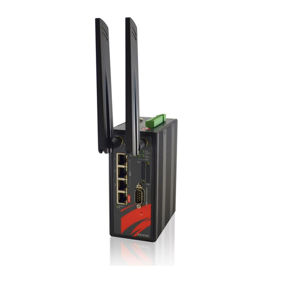
CHAPTER 1. INTRODUCTION 1.4 Hardware Panel Layout This chapter describes the panel and interface layout of hardware. [Front Panel View] [Top Panel View] Index No. Description Fast Ethernet port 1~3 WAN port SIM card slot SMA antenna connectors LED indicators (SYS, Call Signal, VPN, SIM1, SIM2) RS-232 Console/COM1 Reset push-button... -
Page 10: Hardware Installation
CHAPTER 2. HARDWARE INSTALLATION 2 Hardware Installation This chapter introduces how to install and connect the hardware. 2.1 LED Indicators Call Signal Call Signal SIM1 SIM2 Normal System UP Low Signal Connected Connected Signal Connected Slow Booting Connecting Connecting Blinking Connected Fast Error... -
Page 11: Serial Port Com1 (Console)
CHAPTER 2. HARDWARE INSTALLATION LAN RX- 10/100 Mbps LAN, RX- Pin Each Ethernet port has two LED indicators. The Green LED indicates Link/ACT, and the Yellow LED indicates Speed. Status Description Connection is down Green (Link/ACT) Blink Data is being transmitted Connection is up 10 Mbps Mode Yellow (Speed) -
Page 12: Install The Sim Card
CHAPTER 2. HARDWARE INSTALLATION 2.4 Install the SIM Card 1. SIM1/SIM2 Card Drawers and Eject Buttons 2. Insert and Remove SIM1/SIM2 Card (1) Before inserting or removing the SIM card, ensure that the power has been turned off and the power connector has been removed from mobile router. (2) Press the button with a paper clip or suitable tool to eject the SIM card from the drawer. -
Page 13: Reset Button
CHAPTER 2. HARDWARE INSTALLATION 2.5 Reset Button Reset button allows you to reboot the unit or restore to factory default setting. Function Operation Reboot Press the button for 1 second Restore to factory default setting Press the button for 5 seconds Note: Press the Reset button and count the time around 5 seconds. -
Page 14: Grounding The Router
CHAPTER 2. HARDWARE INSTALLATION 2.8 Grounding the Router To prevent the noise and surge effect, please connect the router to the site ground wire by the ground screw before turning on the router. Ring-type Fork-type terminal terminal 2.9 Pin Assignments... -
Page 15: Connecting I/O Ports
CHAPTER 2. HARDWARE INSTALLATION 2.10 Connecting I/O Ports (1) Digital Input DI1 & DI2 The unit has four terminals on the terminal block for the Digital inputs. Description DI1_I1 Digital INPUT 1 DI1_COM Digital INPUT 1 DI2_I2 Digital INPUT 2 DI2_COM Digital INPUT 2 Note:... -
Page 16: Serial Port Com2 (Rs-232)
CHAPTER 2. HARDWARE INSTALLATION 2.11 Serial Port COM2 (RS-232) The serial port COM2 is a RS-232 interface. Description COM2 Serial Port, RXD Signal (INPUT) COM2 Serial Port, TXD Signal (OUTPUT) COM2 Serial Port, Signal Ground 2.12 Serial Port COM3 (RS-485) The serial port COM3 is a RS-485 interface. -
Page 17: Dip Switch
CHAPTER 2. HARDWARE INSTALLATION 2.13 DIP Switch A built-in 120 ohm terminal resistor can be activated by DIP switch. Pull high or Pull low resistor adjustments are also available. It improves the communication on RS-485 networks for specific application. Switch 1 and 2 set the pull high/low resistor Switch 3 enables or disables the termination resistor Pull High (510 ohm) / SW 1 (Pull Low) -
Page 18: Configuration Via Web Browser
CHAPTER 3. WEB CONFIGURATIONS 3 Configuration via Web Browser 3.1 Access the Web Interface The web configuration is an HTML-based management interface for quick and easy set up of the Mobile Router. Monitoring of the status, configuration and administration of the router can be done via the Web interface. -
Page 19: Status
CHAPTER 3. WEB CONFIGURATIONS Status > WAN Ethernet Item Description Attribute IPv4 Address Ethernet WAN obtain IPv4 Address. IPv4 Mask Ethernet WAN obtain IPv4 Mask. 3.2 Status When you enter the web browser in the beginning, the interface displays the status of router to inform you of Cellular Attribute, Dual SIM information, the current connectivity of WAN Ethernet and LAN Ethernet. -
Page 20: Configuration > System
CHAPTER 3. WEB CONFIGURATIONS Status > LAN Ethernet Item Description Attribute IPv4 Address Ethernet LAN is assigned IPv4 Address. IPv4 Mask Ethernet LAN is assigned IPv4 Mask. IPv6 Address Ethernet LAN is assigned IPv6 Address. 3.3 Configuration > System This system section provides you to configure the following items, including Time and Date, COM Ports, Logging, Alarm, Ethernet Ports, Modbus Static Route, and RIP. - Page 21 CHAPTER 3. WEB CONFIGURATIONS II. Manual Set up the information of time and date, including year, month, date, and hour, minute, and second. Set up your local time zone. Click Apply to submit your configuration changes. III. Time Zone Setup ...
- Page 22 CHAPTER 3. WEB CONFIGURATIONS Set up Ahead of standard time. Set up the information of Start Date/Time, including Month, Week, Day, Hour and Minute. Set up the information of End Date/Time, including Month, Week, Day, Hour and Minute.
-
Page 23: System > Com Ports
CHAPTER 3. WEB CONFIGURATIONS 3.3.2 System > COM Ports This section provides you to configure the COM port settings and remotely manage the device through the virtual COM setting. For the remote management, the managed device should be connected to the mobile router by serial interface either RS232 or RS485. Note: The COM 1 and COM 2 are RS232 interface, and the COM 3 is RS485 interface. -
Page 24: System > Logging
CHAPTER 3. WEB CONFIGURATIONS System > COM Ports Item Description Edit Configuration Baud Rate Select from the current Baud Rate. Data Select from 7 bit or 8 bit. Parity Select from the information of Parity. Stop Select from 1 bit or 2 bit. Flow Control Select from none, Xon/Xoff or hardware. -
Page 25: Logging > Logging
CHAPTER 3. WEB CONFIGURATIONS > > (1) Logging section provides you to control all logging records. (2) Users need to select Apply to confirm your settings. System > Logging > Logging Item Description Turn on/off the logging configuration. Select from Disable or Mode Enable. -
Page 26: System > Alarm
CHAPTER 3. WEB CONFIGURATIONS System > Logging > Log Item Description Filter Filter the required data quickly. Date Show the date of log for each logging data. Group Show the group of software functions. Module Show the module of group of software functions. Message Show the messages for each logging data. - Page 27 CHAPTER 3. WEB CONFIGURATIONS System > Alarm Item Description Turn on/off the Alarm configuration. Select from Disable or Mode Enable. The default is Enable. Select from SMS, DI 1, DI 2, VPN disconnect and WAN disconnect as input to trigger alarm. SMS: It means team members on selected week day can ...
-
Page 28: Alarm > Name Group
CHAPTER 3. WEB CONFIGURATIONS > > (1) How to create your group Name a group: Click Group for naming and the interface will show the group’s name in the Group setting as below. > > (2) How to edit each user’s information in every group Select your naming group and click Add button to edit your user’s ... - Page 29 CHAPTER 3. WEB CONFIGURATIONS After submitting your setting, the interface returns to Group window setting. Please click your naming group to show the user’s information that you have edited. button to add the new user’s information. You can click ...
-
Page 30: System > Ethernet Ports
CHAPTER 3. WEB CONFIGURATIONS 3.3.5 System > Ethernet Ports This section allows you to configure the Ethernet Ports. System > Ethernet Ports Item Description Status Show the connectivity status of LAN and WAN. Select from Auto, 100M Full, 100M Half, 10M Full, 10M Half Configurations and Disable. -
Page 31: System > Client List
CHAPTER 3. WEB CONFIGURATIONS 3.3.7 System > Client List This section allows you to understand how many devices have been connected and their status from the router. There are two types, one is DHCP Client and the other is Online. The default is both types to show all status when the router is on DHCP Client and Online. -
Page 32: Wan > Priority
CHAPTER 3. WEB CONFIGURATIONS 3.4.1 WAN > Priority You can set up the priority of WAN. WAN > Priority Item Description Auto: WAN Ethernet is first priority and second priority is LTE. The default is Auto. Priority LTE Only: The priority is only LTE. ... - Page 33 CHAPTER 3. WEB CONFIGURATIONS When selecting “DHCP Client”, you can set up DNS Server Configuration. For IPv4 DNS Server, it provides three options to set up and each option has provided with “From ISP”, “User Defined” and “None” to configure. WAN >...
- Page 34 CHAPTER 3. WEB CONFIGURATIONS WAN > Ethernet Item Description Static IPv4 Configuration IP Address Fill in the IP Address. IP Mask Fill in the IP Mask. Gateway Address Fill in Gateway Address. DNS Server Configuration IPv4 DNS Server #1 The IPv4 DNS server IP is input by user. IPv4 DNS Server #2 IPv4 DNS Server #3...
-
Page 35: Ethernet Ping Health
CHAPTER 3. WEB CONFIGURATIONS If you configure “WAN Priority” to “Auto” mode, the system would choose the cost effective connection first such as Ethernet. However in case the Ethernet connection exist but it is unable to access internet; you can enable “Ethernet Ping Health” and the system would switch to LTE connection and switch back whenever Ethernet is able to access internet again. -
Page 36: Wan > Ipv6 Dns
CHAPTER 3. WEB CONFIGURATIONS 3.4.3 WAN > IPv6 DNS This section allows you to set up IPv6 DNS Server Configuration. For IPv6 DNS Server, it provides three options to set up and each option has provided with “From ISP”, “User Defined” and “None” to configure. -
Page 37: Configuration > Lte
CHAPTER 3. WEB CONFIGURATIONS WAN > IPv6 DNS Item Description DNS Server Configuration Each setting DNS Server has three options, including From ISP, User Defined and None. IPv6 DNS Server #1 When you select From ISP, the IPv6 DNS server IP is ... -
Page 38: Lte Ping Health
CHAPTER 3. WEB CONFIGURATIONS LTE > LTE Config Item Description Auto Automatically connect the possible band. 4G Only Connect to 4G network only. 3G Only Connect to 3G network only. 2G Only Connect to 2G network only. For LTE connection, you can enable “LTE Ping Health” to keep alive to avoid base station kicking out the device in idle time. -
Page 39: Lte > Dual Sim
CHAPTER 3. WEB CONFIGURATIONS 3.5.2 LTE > Dual SIM This section allows you to understand the status of connectivity for Dual SIM, SIM1 and SIM2. The Used SIM item has three options and the default is on Dual SIM when first connection. The Connect Retry Number field can set up the re-connecting time if one of the SIM cards on Dual SIM mode can’t connect successfully. - Page 40 CHAPTER 3. WEB CONFIGURATIONS Change SIM PIN:If you want to change SIM PIN code, you can click Change button and type old SIM PIN code and new SIM PIN code. Please aware not to exceed the retry number (PIN remaining number and PUN remaining number).
- Page 41 CHAPTER 3. WEB CONFIGURATIONS Note: The interface will be shown the tick symbol at the same time when each SIM Card has been connected.
- Page 42 CHAPTER 3. WEB CONFIGURATIONS LTE > Dual SIM Item Description Connect Policy Current SIM Card Display which SIM slot is using. Connect: After manually disconnect, user can only click Connect button to get connection or reboot the device to make it automatically connect.
-
Page 43: Lte > Usage Display
CHAPTER 3. WEB CONFIGURATIONS 3.5.3 LTE > Usage Display This section shows the status of current SIM card, operator, IMSI and the charts for Real Time, Hourly, Daily, Weekly, and Monthly. (1) Real-Time Usage: Real-Time Usage Rate: It displays real-time Download/Upload/Total MB per seconds for current using SIM card and the view window size is 60 seconds. - Page 44 CHAPTER 3. WEB CONFIGURATIONS (2) Hourly Usage: It displays Download/Upload/Total MB per hour in one day for current using SIM card and the view window size is 24 hours.
- Page 45 CHAPTER 3. WEB CONFIGURATIONS (3) Daily Usage: It displays Download/Upload/Total MB per day in one month for current using SIM card and the view window size is 31 days.
- Page 46 CHAPTER 3. WEB CONFIGURATIONS (4) Weekly Usage: It displays Download/Upload/Total MB per day in one week for current using SIM card and the view window size is 7 days.
-
Page 47: Lte > Sms
CHAPTER 3. WEB CONFIGURATIONS (5) Monthly Usage: It displays Download/Upload/Total MB per month in one year for current using SIM card and the view window size is 12 months. 3.5.4 LTE > SMS This section provides two settings, one is SMS Action and the other is View SMS. (1) When enabling SMS Action, it allows you by sending key words SMS to trigger device setting/action/query status. -
Page 48: Configuration > Lan
CHAPTER 3. WEB CONFIGURATIONS (2) For View SMS, this section allows you to review the information of SMS that you have received, including the state, phone and date and time. You can click view button to review all messages. 3.6 Configuration > LAN This section allows you to configure LAN IPv4, LAN IPv6, VLAN and Subnet. -
Page 49: Lan > Ipv4
CHAPTER 3. WEB CONFIGURATIONS 3.6.1 LAN > IPv4 Set up your IP Address and IP Mask. Also, fill in the information of DHCP Server Configuration. LAN > IPv4 Item Description IP Address:10.1.1.1 IP Mask:255.255.255.0 LAN IPv4 Both of them are default, you can change them according to your local IP Address and IP Mask. - Page 50 CHAPTER 3. WEB CONFIGURATIONS LAN > IPv6 Item Description This section provides two types, including Delegate Prefix from WAN and Static. LAN IPv6 Static Address: You need to input the static address when you select the static type. Delegate Prefix Select this option to automatically obtain an IPv6 network prefix from the ...
-
Page 51: Lan > Vlan
CHAPTER 3. WEB CONFIGURATIONS 3.6.3 LAN > VLAN This section allows you to set up VLAN that provides a network segmentation system to distinguish the LAN clients and separate them into different LAN subnet for enhancing security and controlling traffic. For 3-port LANs, the VLAN Mode allows you to select Off, Tag Base (802.1p) or Port Base. - Page 52 CHAPTER 3. WEB CONFIGURATIONS LAN > VLAN (3-port LANs) > Tag Base Item Description Mode The VLAN mode is Off or Tag Base (802.1p VLAN). Enable The assigned row of settings are enabled. Subnet Sets the IP address, IP mask and DHCP server. The VLAN ID range is from 1 to 4094.
-
Page 53: Lan > Subnet
CHAPTER 3. WEB CONFIGURATIONS LAN > VLAN (3-port LANs) > Port Base Item Description Mode The VLAN mode is Off, Tag Base (802.1p VLAN) or Port Base. Enable The assigned row of setting are enabled. The port is shown to assign the port to a VLAN which the device is Port connected from LAN 1, LAN2, LAN3 and Router. -
Page 54: Ip Routing
CHAPTER 3. WEB CONFIGURATIONS 3.7 IP Routing This section allows you to configure the Static Route and RIP. 3.7.1 IP Routing > Static Route This section allows you to configure the Static Route. A static route is a pre-determined path that network information must follow to reach a specific host or network. - Page 55 CHAPTER 3. WEB CONFIGURATIONS (2) Input the IP address of destination/gateway from IPv4 and IPv6 at the same time. The interface is shown in Apply fail to notice. You should select either IPv4 or IPv6 as the address of destination/gateway. The status tab shows the information from the settings of static route.
-
Page 56: Ip Routing > Rip
CHAPTER 3. WEB CONFIGURATIONS 3.7.2 IP Routing > RIP This section allows you to configure RIP and select the mode from Disable or Enable. The default is Disable. Note: RIP (Routing Information Protocol, RFC 2453) is an Interior Gateway Protocol (IGP) and is commonly used in internal networks. -
Page 57: Ip Routing > Ospf
CHAPTER 3. WEB CONFIGURATIONS System > RIP > Interfaces Item Description Interfaces Select from Off or On to use or not to use the RIP function in the Mode interface. Interface Select from eth1(WAN Ethernet) or LAN. Select from none or md5 to approve authentication. Note: Authentication Please offer Key and Key ID when you select md5 to use... - Page 58 CHAPTER 3. WEB CONFIGURATIONS IP Routing > OSPF > General Item Description General Off:OSPF function is off. Mode On:OSPF function is on. Off:Not redistribute local routes from the device's own routing table. Redistribute local routes On: Redistribute local routes from the device's own routing table.
- Page 59 CHAPTER 3. WEB CONFIGURATIONS IP Routing > OSPF > Interfaces Item Description Interfaces Select from Off or On to use or not to use the OSPF function in Mode the interface. Interface Select from eth1(WAN Ethernet) or LAN. Select from none or md5 to approve authentication. Note: Authentication Please offer Key and Key ID when you select md5 to use...
- Page 60 CHAPTER 3. WEB CONFIGURATIONS (3) Networks Configuration There are 2 parts for OSPF Networks configuration. OSPF Networks Summary You can edit and delete the existed OSPF networks. OSPF Networks Add/Edit This sub configuration is used to configure all the networks, the maximum is 2. IP Routing >...
-
Page 61: Ip Routing > Bgp
CHAPTER 3. WEB CONFIGURATIONS 3.7.4 IP Routing > BGP This section allows you to set up BGP with three sub configurations, including General, Neighbors and Networks configuration. (1) General Configuration IP Routing > BGP > General Item Description General Off:BGP function is off. Mode ... - Page 62 CHAPTER 3. WEB CONFIGURATIONS (2) Neighbor Configuration The neighbors sub configuration is used to configure all the BGP routers to peer with and the maximum neighbors is 16. IP Routing > BGP > Neighbor Item Description Neighbor Mode Select from Off or On to enable the neighbor setting IP Address Set IP address of the peer router AS Number...
- Page 63 CHAPTER 3. WEB CONFIGURATIONS IP Routing > BGP > Networks Item Description Networks Mode Select from Off or On to enable the network Prefix Set Prefix of the network Prefix Length Set Length of the prefix...
-
Page 64: Configuration > Service
CHAPTER 3. WEB CONFIGURATIONS 3.8 Configuration > Service This section allows you to configure OpenVPN, IPSec, Port Forwarding, Dynamic DNS, DMZ, SNMP, IP Filter, MAC Filter, URL Filter, VRRP, MQTT, UPnP, SMTP, NAT, IP Alias and GRE. 3.8.1 Service > Configuration OpenVPN (1) This section allows you to configure the OpenVPN parameters. - Page 65 CHAPTER 3. WEB CONFIGURATIONS (2) From Setting tab, you can set up the connection of OpenVPN. From Log tab, the interface will be shown the status of connection to make you follow the suitation whenever is successful or fail connection.
-
Page 66: Set Up Openvpn Client
CHAPTER 3. WEB CONFIGURATIONS Service > OpenVPN Item Description Mode Turn on/off OpenVPN to select Disable or Enable. Server: Tick to enable OpenVPN server tunnel. Client: Tick to enable OpenVPN client tunnel. The default is Client. VPN Mode Custom: This option allows user to use the .ovpn ... - Page 67 CHAPTER 3. WEB CONFIGURATIONS Service > OpenVPN > Client VPN Mode Item Description Client Client Mode Only support the Roadwarrior mode. Server Address Fill in WAN IP of OpenVPN server. Select from Off or On. This setting needs to match the server Route Client Networks side.
-
Page 68: Set Up Openvpn Server
CHAPTER 3. WEB CONFIGURATIONS This section allows you to configure the server status of VPN Mode. Note: When selecting the On option of Route Client Networks, the OpenVPN server will route the client traffic or not. You should fill in the client IP and netmask when this option is enabled. -
Page 69: Set Up Openvpn Custom
CHAPTER 3. WEB CONFIGURATIONS Service > OpenVPN > Server VPN Mode Item Description Server Client Mode Only support the Roadwarrior mode. VPN Network The network ID for OpenVPN virtual network. VPN Netmask The netmask for OpenVPN virtual network. Select from Off or On. The OpenVPN server will route the client Roadwarrior: traffic or not. -
Page 70: Service > Configuration Ipsec
CHAPTER 3. WEB CONFIGURATIONS Service > OpenVPN > Custom VPN Mode Item Description Mode Select from Disable or Enable. The default is Disable. Select from custom mode. VPN Mode Custom Config Import OpenVPN configuration. Fill in the username if the imported file has already set up the Username username. - Page 71 CHAPTER 3. WEB CONFIGURATIONS...
-
Page 72: Ipsec > Connections
CHAPTER 3. WEB CONFIGURATIONS Service > IPSec > General setting Item Description Mode Select from Disable or Enable. The default is Disable. Protocol Select from IKEv1 or IKEv2. Aggressive mode Select from Enable or Disable (default). (Note: The Aggressive mode is for IKEv2.) Encryption Select from AES128 (default), AES192, AES256 or 3DES. - Page 73 CHAPTER 3. WEB CONFIGURATIONS...
-
Page 74: Ipsec > The Setting Of X.509 Certificates
CHAPTER 3. WEB CONFIGURATIONS Service > IPSec > Connections Item Description Mode Select from Disable or Enable. The default is Disable. Name Fill in the name of IPSec Tunnel. Status Display the connection status of IPSec. Local Host Fill in the WAN IP of mobile router. Subnet Fill in the subnet for the LAN of mobile router. -
Page 75: Service > Configuration Port Forwarding
CHAPTER 3. WEB CONFIGURATIONS 3.8.3 Service > Configuration Port Forwarding This section allows you to set up Port Forwarding and click edit button to configure. -
Page 76: Service > Dynamic Dns
CHAPTER 3. WEB CONFIGURATIONS Service > Port Forwarding Item Description Turn on/off Port Forwarding to select Disable or Enable. The Mode default is Disable. Description Descript the name of Port Forwarding. Protocol Select from UDP or TCP Client which depends on the application. Source Port Begin Fill in the beginning of source port. - Page 77 CHAPTER 3. WEB CONFIGURATIONS Service > Dynamic DNS Item Description Mode Turn on/off this function to select Disable or Enable. The default is Disable. Select the Service Provider of Dynamic DNS. Service Provider Host Name Fill in your registered Host Name from Service Provider. Fill in your Token ID from Service Provider.
-
Page 78: Service > Dmz
CHAPTER 3. WEB CONFIGURATIONS 3.8.5 Service > DMZ This section allows you to set the DMZ configuration. Service > DMZ Item Description Select from Disable or Enable. The default is Disable. Mode Fill in your Host IP Address. Host IP Address 3.8.6 Service >... -
Page 79: Snmp V3 User Configuration
CHAPTER 3. WEB CONFIGURATIONS Service > SNMP > Community Item Description Mode Select from Disable or Enable to configure SNMP. Configure community setting with three options, including # 1, # 2 Community and #3. Mode Select from Disable or Enable. Name Name each community. -
Page 80: Snmp Trap Configuration
CHAPTER 3. WEB CONFIGURATIONS This section allows you to set up the SNMP trap configuration when you select the SNMP trap function from Alarm output of system for your router. With SNMP trap setting, you can know the status of remote device. Service >... -
Page 81: Service > Tr069
CHAPTER 3. WEB CONFIGURATIONS 3.8.7 Service > TR069 This section allows you to set up TR069 client configuration. You can get information how to install TR069 Server (GenieACS Installation) from the application configuration chapter. Service > TR069 Item Description Mode Select from Disable or Enable. -
Page 82: Service > Ip Filter
CHAPTER 3. WEB CONFIGURATIONS 3.8.8 Service > IP Filter This section allows you to configure IP Filter. After clicking button, you can edit your IP protocol, source/port and destination/port. (1) The default is Disable Mode as the following interface. Service > IP Filter Item Description Mode... -
Page 83: Service > Mac Filter
CHAPTER 3. WEB CONFIGURATIONS (2) When selecting Enable Mode, the protocol is TCP. The source IP has IPv4 and IPv6 setting formats. (3) For Source IP, there are three types to input your source IP that depends on your requirement, including single IP, IP with Mask or giving a range of IP. The following table provides some examples. -
Page 84: Service > Url Filter
CHAPTER 3. WEB CONFIGURATIONS Service > MAC Filter Item Description Mode Select from Disable or Enable. The default is Disable. MAC Address Fill in your MAC address. Setting up MAC address, please use : colon symbol (e.g. xx : xx : xx: xx) or – hyphen Note: symbol to mark (e.g. -
Page 85: Service > Vrrp
CHAPTER 3. WEB CONFIGURATIONS Please not include “https://” for the URL address in the Full Filter. Note: Service > URL Filter Item Description Mode Select from Disable or Enable. The default is Disable. Filter Select from Key or Full. The default is Key. Key/Full Fill in your Key/Full information. -
Page 86: Service > Mqtt
CHAPTER 3. WEB CONFIGURATIONS 3.8.12 Service > MQTT This section makes you configure MQTT which allows the MQTT client to send the message within specific topic or channel. By default, the router does not allow anonymous to read/write the MQTT topic or channel. Thus, you need to create the account with username and password for MQTT client in the web UI. -
Page 87: Service > Upnp
CHAPTER 3. WEB CONFIGURATIONS 3.8.13 Service > UPnP This section allows you to set up UPnP confirguration to select the mode from Disable or Enable. The default UPnP is enabled for the Mobile Router. Note: UPnP™ (Universal Plug and Play) is a set of protocols that allows a PC to automatically discover other UPnP devices (anything from an Internet gateway device to a light switch), retrieve an XML description of the device and its services, control the device, and subscribe to real-time event notification. -
Page 88: Service > Smtp
CHAPTER 3. WEB CONFIGURATIONS 3.8.14 Service > SMTP This section provides you to send your email for the server. For instance, the email will be sent to notify when the Alarm has a nofitication by the server. Service > SMTP Item Description Mode... -
Page 89: Service > Ip Alias
CHAPTER 3. WEB CONFIGURATIONS 3.8.16 Service > IP Alias This section allows you to set IP Alias configuration. IP Alias is associating more than one IP address to a network interface. With IP Alias, one node on a network can have multiple connections to a network, each serving a different purpose. IP Alias can be used to provide multiple network addresses on a single physical interface. -
Page 90: Management
CHAPTER 3. WEB CONFIGURATIONS by the tunnel source and tunnel destination addresses at each endpoint. The GRE Mode is on. Service > IP Alias Item Description Mode Select from Off or On to enable GRE. Local Address Set local address of the GRE tunnel. Remote Address Set remote address of the GRE tunnel. -
Page 91: Identification
CHAPTER 3. WEB CONFIGURATIONS 3.9.1 Identification This section allows you to confirm the profile of router, current software, firmware version and system uptime. Management > Identification Item Description Host Name Show the host name of mobile router. MAC Address Show the MAC address. Software Version Show the current software version. -
Page 92: Firmware
CHAPTER 3. WEB CONFIGURATIONS 3.9.3 Firmware This section provides you to upgrade the firmware of router. (1) Click Select the firmware to upgrade button to choose your current firmware version in your (2) Select Upgrade button to update. (3) After upgrading successfully, the router will reboot automatically. 3.9.4 Configuration This section supports you to export or import the configuration file. - Page 93 page is intentionally left blank. Revision History Version Date Change Note 6/28/2017 Initial Release Revise the product name, introduction and features. Add MTBFs and remove Telnet from remote management for the specifications. Update the front panel pictures of products. ...
Need help?
Do you have a question about the ICR-4103 and is the answer not in the manual?
Questions and answers