Table of Contents
Advertisement
Quick Links
Advertisement
Table of Contents

Related Manuals for CTC Union ICR-4103 Series


Summary of Contents for CTC Union ICR-4103 Series
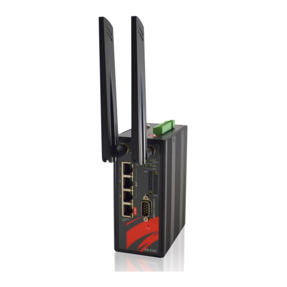
- Page 1 ICR-4103 4G LTE Cellular Router...
- Page 2 CTC Union Technologies makes no warranty, representation, or guarantee regarding the suitability of its products for any particular purpose, nor does CTC Union assume any liability arising out of the application or use of any product and specifically disclaims any and all liability, including without limitation any consequential or incidental damages.
- Page 3 This document is the current official release manual. Contents are subject to change without prior notice. Please check CTC Union's website for any updated manual or contact us by E-mail at sales@ctcu.com. Please address any comments for improving this manual or to point out omissions or errors to marketing@ctcu.com.
-
Page 4: Table Of Contents
TABLE OF CONTENTS Table of Contents Introduction ........................7 1.1 Features .......................... 7 1.2 Specifications ........................8 1.3 Mechanical Dimensions ....................8 1.4 Hardware Panel Layout ....................9 Hardware Installation ...................... 10 2.1 LED Indicators ....................... 10 2.2 Ethernet Port ......................... 10 2.3 Serial Port COM1 (Console) .................. - Page 5 TABLE OF CONTENTS 3.6.1 LTE Config ....................... 40 3.6.1.1 LTE Configuration ..............................40 3.6.1.2 LTE Ping Health ..............................41 3.6.2 Dual SIM ........................42 3.6.3 Usage Display ......................46 3.6.4 SMS ......................... 52 3.6.4.1 Configuration ..............................52 3.6.4.2 Activate DO Control via SMS ..........................53 3.6.5 Service Cell ......................
- Page 6 TABLE OF CONTENTS 3.10.1.1 SNMP configuration ............................127 3.10.1.2 SNMP v3 User configuration ..........................127 3.10.1.3 SNMP trap configuration ..........................128 3.10.2 TR069 ........................129 3.10.3 Dynamic DNS ...................... 131 3.10.4 VRRP ........................132 3.10.5 MQTT ........................133 3.10.6 UPnP ........................135 3.10.7 SMTP ........................
-
Page 7: Introduction
SIM that support failover and roaming over to ensure uninterrupted connectivity for mission-critical cellular communications. With flexible LAN / WAN Ethernet options, ICR-4103 series allow you to customize your professional applications in diverse environments. Integrated with WAN, LAN, built-in DI/DO... -
Page 8: Specifications
CHAPTER 1. INTRODUCTION 1.2 Specifications LTE Interface Software Network Protocols: FDD LTE: B1/B3/B5/B7/B8/B20 IPv4, IPv6, IPv4/IPv6 dual stack, DHCP server and TDD LTE: B38/B40/B41 client, WCDMA: B1/B5/B8 PPPoE, Static IP, SNTP, DNS Proxy, Modbus, VRRP, GSM: 900/1800 MHz OSPF, Message Queue Telemetry, Transport (MQTT ... -
Page 9: Hardware Panel Layout
CHAPTER 1. INTRODUCTION 1.4 Hardware Panel Layout This chapter describes the panel and interface layout of hardware. [Front Panel View] [Top Panel View] Index No. Description Fast Ethernet port 1~3 WAN port SIM card slot SMA antenna connectors LED indicators (SYS, Call Signal, VPN, SIM1, SIM2) RS-232 Console/COM1 Reset push-button... -
Page 10: Hardware Installation
CHAPTER 2. HARDWARE INSTALLATION 2 Hardware Installation This chapter introduces how to install and connect the hardware. 2.1 LED Indicators Call Signal Call Signal SIM1 SIM2 Normal System UP Low Signal Connected Connected Signal Connected Slow Booting Connecting Connecting Blinking Connected Fast Error... - Page 11 CHAPTER 2. HARDWARE INSTALLATION Description Function LAN TX+ 10/100 Mbps LAN, TX+ Pin LAN TX- 10/100 Mbps LAN, TX- Pin LAN RX+ 10/100 Mbps LAN, RX+ Pin LAN RX- 10/100 Mbps LAN, RX- Pin Each Ethernet port has two LED indicators. The Green LED indicates Link/ACT, and the Yellow LED indicates Speed.
-
Page 12: Serial Port Com1 (Console)
CHAPTER 2. HARDWARE INSTALLATION 2.3 Serial Port COM1 (Console) The serial port COM1 is a standard Sub-D connector. Description Direction Ground... -
Page 13: Install The Sim Card
CHAPTER 2. HARDWARE INSTALLATION 2.4 Install the SIM Card 1. SIM1/SIM2 Card Drawers and Eject Buttons 2. Insert and Remove SIM1/SIM2 Card (1) Before inserting or removing the SIM card, ensure that the power has been turned off and the power connector has been removed from mobile router. (2) Press the button with a paper clip or suitable tool to eject the SIM card from the drawer. -
Page 14: Reset Button
CHAPTER 2. HARDWARE INSTALLATION 2.5 Reset Button Reset button allows you to reboot the unit or restore to factory default setting. Function Operation Reboot Press the button for 1 second Restore to factory default setting Press the button for 5 seconds Note: Press the Reset button and count the time around 5 seconds. -
Page 15: Grounding The Router
CHAPTER 2. HARDWARE INSTALLATION 2.8 Grounding the Router To prevent the noise and surge effect, please connect the router to the site ground wire by the ground screw before turning on the router. Ring-type Fork-type terminal terminal 2.9 Pin Assignments... -
Page 16: Connecting I/O Ports
CHAPTER 2. HARDWARE INSTALLATION 2.10 Connecting I/O Ports (1) Digital Input DI1 & DI2 The unit has four terminals on the terminal block for the Digital inputs. Description DI1_I1 Digital INPUT 1 DI1_COM Digital INPUT 1 DI2_I2 Digital INPUT 2 DI2_COM Digital INPUT 2 Note:... -
Page 17: Serial Port Com2 (Rs-232)
CHAPTER 2. HARDWARE INSTALLATION 2.11 Serial Port COM2 (RS-232) The serial port COM2 is a RS-232 interface. Description COM2 Serial Port, RXD Signal (INPUT) COM2 Serial Port, TXD Signal (OUTPUT) COM2 Serial Port, Signal Ground... -
Page 18: Serial Port Com3 (Rs-485)
CHAPTER 2. HARDWARE INSTALLATION 2.12 Serial Port COM3 (RS-485) The serial port COM3 is a RS-485 interface. Description COM3 Serial Port, Data- (B) wire COM3 Serial Port, Data+ (A) wire 2.13 DIP Switch A built-in 120 ohm terminal resistor can be activated by DIP switch. Pull high or Pull low resistor adjustments are also available. -
Page 19: Configuration Via Web Browser
CHAPTER 3. WEB CONFIGURATIONS 3 Configuration via Web Browser 3.1 Access the Web Interface The web configuration is an HTML-based management interface for quick and easy set up of the Mobile Router. Monitoring of the status, configuration and administration of the router can be done via the Web interface. - Page 20 CHAPTER 3. WEB CONFIGURATIONS Enter the new Super User password and retype the password to confirm. Then, click Apply button. The system needs a reboot to take new password into effect. Note: After changing the User Name and Password, we strongly recommend that you save them because another time when you login, new User Name and Password have to be used so as to successfully login to the system.
-
Page 21: Navigate The Web Configurator
CHAPTER 3. WEB CONFIGURATIONS 3.2 Navigate the Web Configurator The main screen is divided into three parts as below. A -Title Bar, B-Navigation Panel and C -Main Window. A : Title Bar The title bar provides some useful instructions that appear the situation of router. Title Bar Item Description... -
Page 22: Status
CHAPTER 3. WEB CONFIGURATIONS 3.3 Status When you enter the web browser and have not logged in, the first item of main menu shows your status that you are a guest. This status only can view status page without any permission to log in. - Page 23 CHAPTER 3. WEB CONFIGURATIONS Status > WAN LTE Item Description Attribute Show the SIM card which the router work with currently: Current SIM SIM Card or Backup SIM. Modem Status Show the status of modem. Operator Display the name of operator. Modem Access Show the router to access protocol type.
-
Page 24: System
CHAPTER 3. WEB CONFIGURATIONS 3.4 System This system section provides you to configure the following items, including Time and Date, COM Ports, Logging, Alarm, Ethernet, Modbus, and Client List. 3.4.1 Time and Date This section allows you to set up the time and date of router and NTP server. There are two modes at Time and Date Setup, including Get from Time Server and Manual. - Page 25 CHAPTER 3. WEB CONFIGURATIONS II. Manual Set up the information of time and date, including year, month, date, and hour, minute, and second. Set up your local time zone. Click Apply to submit your configuration changes.
- Page 26 CHAPTER 3. WEB CONFIGURATIONS III. Time Zone Setup Set up Daylight Savings as On. Set up Ahead of standard time. Set up the information of Start Date/Time, including Month, Week, Day, Hour and Minute. Set up the information of End Date/Time, including Month, Week, Day, Hour and Minute.
-
Page 27: Com Ports
CHAPTER 3. WEB CONFIGURATIONS 3.4.2 COM Ports This section provides you to configure the COM port settings and remotely manage the device through the virtual COM setting. For the remote management, the managed device should be connected to the mobile router by serial interface either RS232 or RS485. Note: The COM 1 and COM 2 are RS232 interface, and the COM 3 is RS485 interface. -
Page 28: Logging
CHAPTER 3. WEB CONFIGURATIONS System > COM Ports Item Description Edit Configuration Baud Rate Select from the current Baud Rate. Data Select from 7 bit or 8 bit. Parity Select from the information of Parity. Stop Select from 1 bit or 2 bit. Flow Control Select from none, Xon/Xoff or hardware. -
Page 29: Logging
CHAPTER 3. WEB CONFIGURATIONS 3.4.3.1 Logging (1) Logging section provides you to control all logging records. (2) Users need to select Apply to confirm your settings. System > Logging > Logging Item Description Turn on/off the logging configuration. Select from Disable or Mode Enable. -
Page 30: Alarm
CHAPTER 3. WEB CONFIGURATIONS System > Logging > Log Item Description Filter Filter the required data quickly. Date Show the date of log for each logging data. Group Show the group of software functions. Module Show the module of group of software functions. Message Show the messages for each logging data. - Page 31 CHAPTER 3. WEB CONFIGURATIONS System > Alarm Item Description Turn on/off the Alarm configuration. Select from Disable or Mode Enable. The default is Enable. Select from SMS, DI 1, DI 2, VPN disconnect and WAN disconnect as input to trigger alarm. SMS: It means team members on selected week day can ...
-
Page 32: Ethernet Ports
CHAPTER 3. WEB CONFIGURATIONS 3.4.5 Ethernet Ports This section allows you to configure the Ethernet Ports. System > Ethernet Ports Item Description Status Show the connectivity status of LAN and WAN. Select from Auto, 100M Full, 100M Half, 10M Full, 10M Half Configurations and Disable. -
Page 33: Modbus
CHAPTER 3. WEB CONFIGURATIONS 3.4.6 Modbus This section allows you to configure the Modbus. Note: This configuration is for Modbus TCP and the function is only for COM 3 (RS485). System > Modbus Item Description Mode Select from Disable or Enable. Port The listening port of Modbus TCP. -
Page 34: Wan
CHAPTER 3. WEB CONFIGURATIONS 3.5 WAN This section allows you to configure WAN, including Priority, LTE Config, Dual SIM, Ethernet and DNS. 3.5.1 Priority You can set up the priority of WAN. WAN > Priority Item Description ETH First: WAN Ethernet is first priority and the second priority ... -
Page 35: Ethernet
CHAPTER 3. WEB CONFIGURATIONS 3.5.2 Ethernet 3.5.2.1 WAN Ethernet Configuration This section provides three options, including DHCP Client, PPPoE Client and Static IPv4. The default is DHCP Client. WAN > Ethernet Item Description There are three options to obtain the IP of WAN Ethernet. DHCP Client: DHCP server-assigned IP address, netmask, ... - Page 36 CHAPTER 3. WEB CONFIGURATIONS WAN > Ethernet Item Description Each setting DNS Server has three options, including From ISP, User Defined and None. IPv4 DNS Server #1 When you select From ISP, the IPv4 DNS server IP is IPv4 DNS Server #2 obtained from ISP.
-
Page 37: Ethernet Ping Health
CHAPTER 3. WEB CONFIGURATIONS WAN > Ethernet Item Description Static IPv4 Configuration IP Address Fill in the IP Address. IP Mask Fill in the IP Mask. Gateway Address Fill in Gateway Address. DNS Server Configuration IPv4 DNS Server #1 IPv4 DNS Server #2 The IPv4 DNS server IP is input by user. - Page 38 CHAPTER 3. WEB CONFIGURATIONS WAN > Ethernet > Ethernet Ping Health Item Description Ethernet Ping Health Select from Disable or Enable. The default is Enable. Interval The interval is from 1 to 60 seconds. IPv4 Host 1 Input the address of IPv4 Host 1. IPv4 Host 2 Input the address of IPv4 Host 2.
-
Page 39: Ipv6 Dns
CHAPTER 3. WEB CONFIGURATIONS 3.5.3 IPv6 DNS This section allows you to set up IPv6 DNS Server Configuration. For IPv6 DNS Server, it provides three options to set up and each option has provided with “From ISP”, “User Defined” and “None” to configure. WAN >... -
Page 40: Lte
CHAPTER 3. WEB CONFIGURATIONS 3.6 LTE This section allows you to configure LTE Config, Dual SIM, Usage Display and SMS. 3.6.1 LTE Config 3.6.1.1 LTE Configuration You can set up the LTE Configuration and LTE Ping Health. For LTE Configuration, you can select from Auto, 4G Only, 3G Only or 2G Only. -
Page 41: Lte Ping Health
CHAPTER 3. WEB CONFIGURATIONS LTE > LTE Config Item Description Auto: Automatically connect the possible band. 4G Only: Connect to 4G network only. LTE Config 3G Only: Connect to 3G network only. 2G Only: Connect to 2G network only. ... -
Page 42: Dual Sim
CHAPTER 3. WEB CONFIGURATIONS 3.6.2 Dual SIM This section allows you to understand the status of connectivity for Dual SIM, SIM1 and SIM2. The Used SIM item has three options and the default is on Dual SIM when first connection. The Connect Retry Number field can set up the re-connecting time if one of the SIM cards on Dual SIM mode can’t connect successfully. - Page 43 CHAPTER 3. WEB CONFIGURATIONS Change SIM PIN:If you want to change SIM PIN code, you can click Change button and type old SIM PIN code and new SIM PIN code. Please aware not to exceed the retry number (PIN remaining number and PUN remaining number).
- Page 44 CHAPTER 3. WEB CONFIGURATIONS Note: The interface will be shown the tick symbol at the same time when each SIM Card has been connected.
- Page 45 CHAPTER 3. WEB CONFIGURATIONS LTE > Dual SIM Item Description Connect Policy Current SIM Card Display which SIM slot is using. Connect: After manually disconnect, user can only click Connect button to get connection or reboot the device to make it automatically connect.
-
Page 46: Usage Display
CHAPTER 3. WEB CONFIGURATIONS Data Limitation Mode Turn on/off the Data Limitation to disable or enable. Already Used Data (MB) Display current used throughput since last reset. Max Data Limitation (MB) Configure max throughput. Monthly Reset Set up the reset time during the month. Now Time Show the current time of system. - Page 47 CHAPTER 3. WEB CONFIGURATIONS (1) Real-Time Usage: Real-Time Usage Rate: It displays real-time Download/Upload/Total MB per seconds for current using SIM card and the view window size is 60 seconds. Real-Time Usage: It displays accumulated real-time Download/Upload/Total MB per seconds for current using SIM card and the view window size is 60 seconds.
- Page 48 CHAPTER 3. WEB CONFIGURATIONS (2) Hourly Usage: It displays Download/Upload/Total MB per hour in one day for current using SIM card and the view window size is 24 hours.
- Page 49 CHAPTER 3. WEB CONFIGURATIONS (3) Daily Usage: It displays Download/Upload/Total MB per day in one month for current using SIM card and the view window size is 31 days.
- Page 50 CHAPTER 3. WEB CONFIGURATIONS (4) Weekly Usage: It displays Download/Upload/Total MB per day in one week for current using SIM card and the view window size is 7 days.
- Page 51 CHAPTER 3. WEB CONFIGURATIONS (5) Monthly Usage: It displays Download/Upload/Total MB per month in one year for current using SIM card and the view window size is 12 months.
-
Page 52: Sms
CHAPTER 3. WEB CONFIGURATIONS 3.6.4 SMS 3.6.4.1 Configuration This section provides two settings, one is SMS Action and the other is View SMS. (1) When enabling SMS Action, it allows you by sending key words SMS to trigger device setting/action/query status. (2) For View SMS, this section allows you to review the information of SMS that you have... -
Page 53: Activate Do Control Via Sms
CHAPTER 3. WEB CONFIGURATIONS received, including the state, phone and date and time. You can click view button to review all messages. 3.6.4.2 Activate DO Control via SMS This section displays how to activate DO control via SMS function. Apart from setting up configurations in SMS page, you also need to set up a list of users (contacts) that would like to send SMS . - Page 54 CHAPTER 3. WEB CONFIGURATIONS Fill in this user's personal information. (2) Create a group for this user. Go to Management > Contacts / On Duty > Duty Schedule and click "Add Group" button to add a new group entry. Tick the checkbox if necessary.
- Page 55 CHAPTER 3. WEB CONFIGURATIONS (3) Enable SMS Action and modify the string on LTE > SMS > SMS Action page...
- Page 56 CHAPTER 3. WEB CONFIGURATIONS (4) Send a message to the device which contains the string that you entered.
-
Page 57: Service Cell
CHAPTER 3. WEB CONFIGURATIONS 3.6.5 Service Cell This section displays two types of Engineer Information, one is Serving Cell, and the other is Lock PCI. Serving Cell displays all parameters, and Lock PCI is to lock physical cell ID. RSRP, RSRQ, and SINR are for LTE connection. -
Page 58: Lock Bands
CHAPTER 3. WEB CONFIGURATIONS LTE > Engineer Item Description Refresh Display all Neighbor Cell Frequency and PCI Lock Perform lock on specific Frequency/PCI Unlock Unlock from the previous lock 3.6.7 Lock Bands This section allows you to select LTE bands that you would like to be locked. LTE >... -
Page 59: Dns
CHAPTER 3. WEB CONFIGURATIONS 3.6.8 DNS This section allows you to setup LTE specific DNS setting. WAN > Ethernet > DHCP Client Item Description Each setting DNS Server has three options, including From ISP, User Defined and None. IPv4 DNS Server #1 When you select From ISP, the IPv4 DNS server IP is ... -
Page 60: Lan
CHAPTER 3. WEB CONFIGURATIONS 3.7 LAN This section allows you to configure LAN IPv4, LAN IPv6, VLAN and Subnet. 3.7.1 IPv4 Set up your IP Address and IP Mask. Also, fill in the information of DHCP Server Configuration. LAN > IPv4 Item Description IP Address:10.1.1.1... -
Page 61: Vlan
CHAPTER 3. WEB CONFIGURATIONS LAN > IPv6 Item Description This section provides two types, including Delegate Prefix from WAN and Static. LAN IPv6 Static Address: You need to input the static address when you select the static type. Delegate Prefix Select this option to automatically obtain an IPv6 network prefix from the ... - Page 62 CHAPTER 3. WEB CONFIGURATIONS Furthermore, the Subnet provides DHCP Server function to allow the third party for the same VLAN to get IP address and IP mask. Therefore, you do not need to configure manually. (Note: The subnet information will show the Subnet window from the LAN catalogue.) There are three ports for Tag Base Mode, including LAN1, LAN2 and LAN3.
-
Page 63: Subnet
CHAPTER 3. WEB CONFIGURATIONS When VLAN Mode is set to Port Base, the VLAN setting window will appear as shown below. For each row, the settings can be enabled or disabled by checkbox and assign the port to communicate each other. There are three ports for Port Base Mode, including LAN1, LAN2 and LAN3. -
Page 64: Ip Routing
CHAPTER 3. WEB CONFIGURATIONS 3.8 IP Routing This section allows you to configure the Static Route and RIP. 3.8.1 IP Static Route This section allows you to configure the Static Route. A static route is a pre-determined path that network information must follow to reach a specific host or network. - Page 65 CHAPTER 3. WEB CONFIGURATIONS System > Static Route Item Description Mode The setting is for full network. Select from Off or On. Settings Mode The setting is for the specific network. Select from Off or On. Name Set up each name for your running host or network. Destination Fill in the destination of a specific subnet or IP from network.
-
Page 66: Ip Rip
CHAPTER 3. WEB CONFIGURATIONS System > Static Route Item Description Mode The setting is open for full network. Select from Off or On. Status Destination Show the status of destination from the setting section. Gateway Show the status of gateway from the setting section. Interface Show the status of interface from the setting section. - Page 67 CHAPTER 3. WEB CONFIGURATIONS System > RIP > Interfaces Item Description Interfaces Select from Off or On to use or not to use the RIP function in the Mode interface. Interface Select from eth1(WAN Ethernet) or LAN. Select from none or md5 to approve authentication. Note: Authentication Please offer Key and Key ID when you select md5 to use...
-
Page 68: Ospf
CHAPTER 3. WEB CONFIGURATIONS 3.8.3 OSPF This section allows you to set up OSPF with three sub configurations, including General, Interfaces and Networks configuration. (1) General Configuration You can have these settings for General configuration. Mode Redistribute local routes ... - Page 69 CHAPTER 3. WEB CONFIGURATIONS IP Routing > OSPF > General Item Description General Off:OSPF function is off. Mode On:OSPF function is on. Off:Not redistribute local routes from the device's own routing table. Redistribute local routes On: Redistribute local routes from the device's own routing table.
- Page 70 CHAPTER 3. WEB CONFIGURATIONS IP Routing > OSPF > Interfaces Item Description Interfaces Select from Off or On to use or not to use the OSPF function in Mode the interface. Interface Select from eth1 (WAN Ethernet), eth2 (WAN LTE) or LAN. Select from none or md5 to approve authentication.
- Page 71 CHAPTER 3. WEB CONFIGURATIONS (3) Networks Configuration There are 2 parts for OSPF Networks configuration. OSPF Networks Summary You can edit and delete the existed OSPF networks. OSPF Networks Add/Edit This sub configuration is used to configure all the networks, the maximum is 2. IP Routing >...
-
Page 72: Bgp
CHAPTER 3. WEB CONFIGURATIONS 3.8.4 BGP This section allows you to set up BGP with three sub configurations, including General, Neighbors and Networks configuration. (1) General Configuration IP Routing > BGP > General Item Description General Off:BGP function is off. Mode ... - Page 73 CHAPTER 3. WEB CONFIGURATIONS (2) Neighbor Configuration The neighbors sub configuration is used to configure all the BGP routers to peer with and the maximum number of neighbors is 16. IP Routing > BGP > Neighbor Item Description Neighbor Mode Select from Off or On to enable the neighbor setting IP Address Set IP address of the peer router...
- Page 74 CHAPTER 3. WEB CONFIGURATIONS IP Routing > BGP > Networks Item Description Networks Mode Select from Off or On to enable the network Prefix Set Prefix of the network Prefix Length Set Length of the prefix...
-
Page 75: Vpn
CHAPTER 3. WEB CONFIGURATIONS 3.9 VPN 3.9.1 OpenVPN 3.9.1.1 Edit OpenVPN Connection (1) This section allows you to configure the OpenVPN parameters. The default mode is Disable. Click button to edit OpenVPN Connection. (2) From Setting tab, you can set up the connection of OpenVPN. - Page 76 CHAPTER 3. WEB CONFIGURATIONS From Log tab, the interface will be shown the status of connection to make you follow the suitation whenever is successful or fail connection. VPN > OpenVPN Item Description Mode Turn on/off OpenVPN to select Disable or Enable. Server: Tick to enable OpenVPN server tunnel.
-
Page 77: Set Up Openvpn Client
CHAPTER 3. WEB CONFIGURATIONS 3.9.1.2 Set up OpenVPN Client This section allows you configure the OpenVPN client route and authentication files. The files could be imported by clicking Import button and the file should be downloaded from OpenVPN server. Service > OpenVPN > Client VPN Mode Item Description Client... -
Page 78: Set Up Openvpn Server
CHAPTER 3. WEB CONFIGURATIONS 3.9.1.3 Set up OpenVPN Server This section allows you to configure the server status of VPN Mode. Note: When selecting the On option of Route Client Networks, the OpenVPN server will route the client traffic or not. You should fill in the client IP and netmask when this option is enabled. -
Page 79: Set Up Openvpn Custom
CHAPTER 3. WEB CONFIGURATIONS Service > OpenVPN > Server VPN Mode Item Description Server Client Mode Only support the Roadwarrior mode. VPN Network The network ID for OpenVPN virtual network. VPN Netmask The netmask for OpenVPN virtual network. Select from Off or On. The OpenVPN server will route the client Roadwarrior: traffic or not. -
Page 80: Ipsec
CHAPTER 3. WEB CONFIGURATIONS VPN > OpenVPN > Custom VPN Mode Item Description Mode Select from Disable or Enable. The default is Disable. Select from custom mode. VPN Mode Custom Config Import OpenVPN configuration. Username Fill in the username if the imported file has already set up the username. -
Page 81: Connections
CHAPTER 3. WEB CONFIGURATIONS VPN > IPsec > General setting Item Description Mode Select from Disable or Enable. The default is Disable. Select from Policy-based or Route-based. The default is Policy-based. Policy-based: transmit traffic that meets the IPsec phase 2 Type local/remote subnet. - Page 82 CHAPTER 3. WEB CONFIGURATIONS (1) IPsec Phase 1 Setting VPN > IPsec > Phrase 1 setting Item Description Mode Select from Disable or Enable. The default is Disable. Name Short name or description. Protocol Select from IKEv1 or IKEv2. The default is IKEv1. Select from Disable or Enable.
- Page 83 CHAPTER 3. WEB CONFIGURATIONS (2) IPsec Phase 2 Setting VPN > IPsec > Phrase 1 setting Item Description Protocol Only support ESP. The encryption algorithm. Encryption Select from AES128 (default), AES192, AES256 or 3DES. The integrity algorithm. Hash Select from MD5, SHA1 (default) or SHA256. The Diffie Hellman Group.
-
Page 84: Authentication Ids
CHAPTER 3. WEB CONFIGURATIONS (3) IPsec Advance Setting VPN > IPsec > Connections Item Description The period time interval to detect dead peers. DPD interval The default is 30 seconds. The max number of retry of dead peer detection. DPD retry The default is 5 times. -
Page 85: Certificates
CHAPTER 3. WEB CONFIGURATIONS VPN > IPsec > Authentication IDs Item Description The identification for authentication. It only work on PSK type. Select from PSK or RSA. The default is PSK. Type PSK: Use the pre-shared key to authenticate the connection. ... -
Page 86: Ca Certificates
CHAPTER 3. WEB CONFIGURATIONS 3.9.2.4 CA Certificates This section provides the CA certificates setting which could check whether the X.509 certificate is valid or not. There is one self-signed CA (generated by the router), and it supports the user import the self-signed CAs to the router. - Page 87 CHAPTER 3. WEB CONFIGURATIONS Certificate Generation There are two kinds of certificate that could be generated by router, one is self-signed CA, the other one is X.509. To generate the self-signed CA certificate: 1. Navigate to CA Certificates tab. 2. Click the button to navigate the Certificate Setting page.
- Page 88 CHAPTER 3. WEB CONFIGURATIONS Certificate Importing Same as the Certificate Generation, the router supports the CA and X.509 certificate importing. To import the CA certificate: 1. Navigate to CA Certificates tab. 2. Click the + Add CA certificate button. 3. Select the CA certificate file from browser window. 4.
-
Page 89: Net-To-Net Configuration
CHAPTER 3. WEB CONFIGURATIONS 3.9.2.5 Net-to-Net Configuration In this case, the IPsec VPN tunnel uses the two LAN side subnet clouds and makes them communicate each other. There are two part settings for the Cellular router IPsec feature. Pre-shared Key authentication Configure Net-to-Net VPN Server 1. - Page 90 CHAPTER 3. WEB CONFIGURATIONS...
- Page 91 CHAPTER 3. WEB CONFIGURATIONS Configure Net-to-Net VPN Client 1. Change Mode from Disable to Enable. 2. Navigate to the Authentication IDs tab. 3. Add the authentication ID Keep ID as blank, Type as PSK and fill the password to Pre-shared Key field. 4.
- Page 92 CHAPTER 3. WEB CONFIGURATIONS...
- Page 93 CHAPTER 3. WEB CONFIGURATIONS IPsec Net-to-Net with Pre-shared Key result Server Client RSA authentication - Server Prepare the self-signed CA certificate 1. Navigate to the CA Certificates tab. 2. Edit the self-signed CA. (Skip it if the self-signed CA is generated.) (1) Fill the information of the self-signed CA (2) Country Name: CN (3) Orgnization Name: Company...
- Page 94 CHAPTER 3. WEB CONFIGURATIONS Prepare the X.509 certificates 1. Navigate to the X.509 Certificates tab. 2. Click the add button to add the X.509 certificate 3. Edit the newly X.509 certificate for the local router. (1) Fill the information of the X.509 certificate (2) Country Name: CN (3) Orgnization Name: Company (4) Common Name: local.IPsec...
- Page 95 CHAPTER 3. WEB CONFIGURATIONS...
- Page 96 CHAPTER 3. WEB CONFIGURATIONS Prepare the authentication IDs 1. Navigate to the Authentication IDs tab. 2. Add tow authentication IDs Keep first one's ID as blank, Type as RSA and select the C=CN, O=Company, CN=local.IPsec X.509 certificate. Keep second one's ID as blank, Type as RSA and select the C=CN, O=Company, CN=remote.IPsec X.509 certificate.
- Page 97 CHAPTER 3. WEB CONFIGURATIONS Setup the connection on VPN server 1. Change Mode from Disable to Enable. 2. Navigate to the Connections tab. 3. Add IPsec connection (1) Edit the phase 1 setting (2) Change Mode from Disable to Enable. (3) Change Auth Type from PSK to RSA.
- Page 98 CHAPTER 3. WEB CONFIGURATIONS RSA authentication – Client Prerequisite for VPN Client with RSA authentication 1. The self-signed CA certificate which generated by VPN server 2. The X.509 certificate and key for remote router which generated by VPN server These files could be downloaded from VPN server.
- Page 99 CHAPTER 3. WEB CONFIGURATIONS Import the CA certificate and the X.509 certificate Please refer the Certificate Importing section of user manual to import the required files. Setup the connection on VPN client 1. Change Mode from Disable to Enable. 2. Navigate to the Authentication IDs tab.
- Page 100 CHAPTER 3. WEB CONFIGURATIONS (1) Edit the phase 1 setting (2) Change Mode from Disable to Enable. (3) Change Auth Type from PSK to RSA. (4) Change the Local ID and select the remote.IPsec (RSA) authenticaion ID. (5) Fill the IP address of VPN server to Remote Host field. ...
- Page 101 CHAPTER 3. WEB CONFIGURATIONS...
- Page 102 CHAPTER 3. WEB CONFIGURATIONS IPsec Net-to-Net with RSA authentication result Server Client...
-
Page 103: Hub-Spoke Topology
CHAPTER 3. WEB CONFIGURATIONS 3.9.2.6 Hub-Spoke Topology This section explains how to set Hub-Spoke Topology and connect two (or more) gateways to a central one. This requires one connection between each spoke and the central hub (n - 1 connections for n gateways) For example, in the Hub-and-Spoke topology, we want to send the essential traffic through IPsec VPN tunnel. - Page 104 CHAPTER 3. WEB CONFIGURATIONS Hub configuration Hub IPsec configuration In this example, we have two spokes on the topology. Thus, the Hub needs to set two IPsec connections for each spoke. 1. Change Mode from Disable to Enable. 2. Change Type from Policy-based to Route-based. 3.
- Page 105 CHAPTER 3. WEB CONFIGURATIONS...
- Page 106 CHAPTER 3. WEB CONFIGURATIONS...
- Page 107 CHAPTER 3. WEB CONFIGURATIONS Hub Static Route configuration 1. Navigate to the IP Routing > Static Route page 2. Add the static route for IPsec Spoke 1 connection Mode: On Destination: 192.168.100.0/24 Interface: Select the IPsec interface by connection number ...
- Page 108 CHAPTER 3. WEB CONFIGURATIONS 5. Add one authentication ID (4) ID: spoke1 (5) Type: PSK (6) Pre-shared Key: testspoke1 6. Apply the changes 7. Navigate to the Connections tab. 8. Add IPsec connection (7) Edit the phase 1 setting (8) Change Mode from Disable to Enable. (9) Change the Local ID and select the spoke1 (PSK) authenticaion ID.
- Page 109 CHAPTER 3. WEB CONFIGURATIONS Spoke 1 Static Route configurtation 1. Navigate to the IP Routing > Static Route page 2. Add the static route for IPsec connection Mode: On Destination: 192.168.200.0/24 Interface: Select the IPsec interface by connection number ...
- Page 110 CHAPTER 3. WEB CONFIGURATIONS Spoke 2 configuration Spoke 2 IPsec configuration 1. Change Mode from Disable to Enable. 2. Change Type from Policy-based to Route-based. 3. Navigate to the Authentication IDs tab. 4. Add default pre-shared key ID: (The ID is blank.) ...
- Page 111 CHAPTER 3. WEB CONFIGURATIONS...
- Page 112 CHAPTER 3. WEB CONFIGURATIONS Spoke 2 Static Route configurtation 1. Naviagte to the IP Routing > Static Route page 2. Add the static route for IPsec connection Mode: On Destination: 192.168.100.0/24 Interface: Select the IPsec interface by connection number ...
-
Page 113: Gre
CHAPTER 3. WEB CONFIGURATIONS 3.9.3 GRE This section allows you to set GRE configuration. The default mode is off. Generic Routing Encapsulation (GRE) is one of the available tunneling mechanisms which uses IP as the transport protocol and can be used for carrying many different passenger protocols. The tunnels behave as virtual point-to-point links that have two endpoints identified by the tunnel source and tunnel destination addresses at each endpoint. -
Page 114: Pptp Server
CHAPTER 3. WEB CONFIGURATIONS 3.9.4 PPTP Server This section provides 2 sub configurations, including General Configuration and Clients Configuration. (1) General Configuration VPN > PPTP Server Item Description Mode Select from Off or On to enable PPTP Server. IP addresses to be used at the local end of the tunneled Server Address PPP links between the server and the client. -
Page 115: L2Tp
CHAPTER 3. WEB CONFIGURATIONS 3.9.5 L2TP This section allows you to set up L2TP and provides three modes for configuration, including Off, Server, and Client Mode. (1) Genernal Mode: The defualt mode is Off as shown in the following interface. (2) Server Mode: Choose the Server mode and the interface will be changed as below. - Page 116 CHAPTER 3. WEB CONFIGURATIONS VPN> L2TP > Server Mode Item Description Mode Select from Off or On to set the client setting. Auth The authentication method for L2TP connection. Available options: PAP, CHAP, MS-CHAP, MS-CHAPv2 Local IP The virtual IP for L2TP server. Remote begin IP The begin address of L2TP client's IP pool.
- Page 117 CHAPTER 3. WEB CONFIGURATIONS (3) Client Mode: Choose the Client mode and the interface will be changed as below. VPN> L2TP > Client Mode Item Description Mode Turn on/off this L2TP connection Server The L2TP server address or hostname. Auth The authentication method for L2TP connection.
- Page 118 CHAPTER 3. WEB CONFIGURATIONS Tip 1: There are two steps to manage the L2TP connection under client mode, First, Fill in the required parameters. Second, Click the Add button to create the L2TP connection. Tip 2: There are two steps to update the L2TP connection. First, Click the Edit button. Second, Update the parameters.
-
Page 119: Firewall
CHAPTER 3. WEB CONFIGURATIONS 3.9.6 Firewall This section allows you to configurate Port Forwarding, DMZ, IP Filter, MAC Filter, URL Filter, and NAT. -
Page 120: Port Forwarding
CHAPTER 3. WEB CONFIGURATIONS 3.9.6.1 Port Forwarding This section allows you to set up Port Forwarding and click edit button to configure. -
Page 121: Dmz
CHAPTER 3. WEB CONFIGURATIONS Service > Port Forwarding Item Description Turn on/off Port Forwarding to select Disable or Enable. The Mode default is Disable. Description Descript the name of Port Forwarding. Protocol Select from UDP or TCP Client which depends on the application. Source Port Begin Fill in the beginning of source port. -
Page 122: Ip Filter
CHAPTER 3. WEB CONFIGURATIONS 3.9.6.3 IP Filter This section allows you to configure IP Filter. After clicking button, you can edit your IP protocol, source/port and destination/port. (1) The default is Disable Mode as the following interface. - Page 123 CHAPTER 3. WEB CONFIGURATIONS Service > IP Filter Item Description Mode Select from Disable or Enable. The default is Disable. Select either Black or White list. Choosing Black list will block the List specific IP address/port listed in the rules. On the other hand, the White list will accept the specific IP address/port listed in the rules.
-
Page 124: Mac Filter
CHAPTER 3. WEB CONFIGURATIONS 3.9.6.4 MAC Filter This section allows you to set up MAC Filter. After clicking button, you can edit your MAC address. Service > MAC Filter Item Description Mode Select from Disable or Enable. The default is Disable. MAC Address Fill in your MAC address. -
Page 125: Url Filter
CHAPTER 3. WEB CONFIGURATIONS 3.9.6.5 URL Filter This section allows you to set up URL Filter. After clicking button, you can edit the type of filter and information. Please not include “https://” for the URL address in the Full Filter. Note: Service >... -
Page 126: Nat
CHAPTER 3. WEB CONFIGURATIONS 3.9.6.6 NAT This section allows you to set NAT configuration. When NAT is on, the router will replace the source private IP address by its Internet public address for outgoing packets, and replace the destination Internet public address by private IP address for incoming packets. -
Page 127: Service
CHAPTER 3. WEB CONFIGURATIONS Firewall > IPS Item Description Mode Turn on/off IPS function (default: Off) Checkbox Select from Enable or Disable (default). Total allow incoming connection number The default number is 10. Checkbox Select from Enable or Disable (default). Max incoming connection retry number The default number is 20. -
Page 128: Snmp Trap Configuration
CHAPTER 3. WEB CONFIGURATIONS For SNMP version 3, you need to register authentication and allow a receiver that confirm the packet was not modified in transit. There are three options to set up SNMP v3 configuration. Service > SNMP > SNMP v3 User configuration Item Description Select from Disable or Enable to configure SNMP. -
Page 129: Tr069
CHAPTER 3. WEB CONFIGURATIONS 3.10.2 TR069 This section allows you to set up TR069 client configuration. You can get information how to install TR069 Server (GenieACS Installation) from the application configuration chapter. - Page 130 CHAPTER 3. WEB CONFIGURATIONS Service > TR069 Item Description Mode Select from Disable or Enable. The default is Disable. ACS URL Fill in the URL address of ACS (Auto-Configuration Server). ACS Username Fill in the ACS username to authenticate the CPE (this router) when connecting to the ACS.
-
Page 131: Dynamic Dns
CHAPTER 3. WEB CONFIGURATIONS 3.10.3 Dynamic DNS This section allows you to set up Dynamic DNS. Service > Dynamic DNS Item Description Mode Turn on/off this function to select Disable or Enable. The default is Disable. Select the Service Provider of Dynamic DNS. Service Provider Host Name Fill in your registered Host Name from Service Provider. -
Page 132: Vrrp
CHAPTER 3. WEB CONFIGURATIONS Note: Several options of Service Provider are provided in drop-down menu and are explained below. Service Provider dynv6.com Host Name Register hostname, e.g. tester.dynv6.net Token ID The token ID, e.g. v_ABjMMQxeAnWv5UwtuVn1QBriynzq Service Provider www.nsupdate.info Host Name Register hostname, e.g. -
Page 133: Mqtt
CHAPTER 3. WEB CONFIGURATIONS Service > VRRP Item Description Mode Select from Disable or Enable. The default is Disable. Specify which VRRP group of this router belong to (1-255). The Group ID default is 1. Enter the priority value from 1 to 254. The larger value has higher Priority priority. - Page 134 CHAPTER 3. WEB CONFIGURATIONS Service > MQTT Item Description Mode Select from Disable or Enable. The default is Disable. Port Fill in the port number of MQTT application. Create the users and show all users’ names. Allow each user to Manage Users delete their name.
-
Page 135: Upnp
CHAPTER 3. WEB CONFIGURATIONS 3.10.6 UPnP This section allows you to set up UPnP confirguration to select the mode from Disable or Enable. The default UPnP is enabled for the Mobile Router. Note: UPnP™ (Universal Plug and Play) is a set of protocols that allows a PC to automatically discover other UPnP devices (anything from an Internet gateway device to a light switch), retrieve an XML description of the device and its services, control the device, and subscribe to real-time event notification. -
Page 136: Ip Alias
CHAPTER 3. WEB CONFIGURATIONS 3.10.8 IP Alias This section allows you to set IP Alias configuration. IP Alias is associating more than one IP address to a network interface. With IP Alias, one node on a network can have multiple connections to a network, each serving a different purpose. IP Alias can be used to provide multiple network addresses on a single physical interface. -
Page 137: Qos (Quality Of Service)
CHAPTER 3. WEB CONFIGURATIONS 3.10.9 QoS (Quality of Service) QoS (Quality of Service) refers to a network's ability to achieve maximum bandwidth and allow minimum bandwidth. It guarantees the minimum and limit the maximum bandwidth for certain class of traffic. The QoS configuration has three parts, including ISP bandwidth, QoS and Status. ... -
Page 138: Qos
CHAPTER 3. WEB CONFIGURATIONS 3.10.9.2 QoS You can select QoS tab and show a overall view for QoS configuration. At right side of window, there are three buttons. Edit botton allows you to edit QoS Entry and configure QoS settings. Up/Down arrow button allow you to adjust priority of the QoS entry. - Page 139 CHAPTER 3. WEB CONFIGURATIONS Classify traffic by following items: Service > QoS Item Description Mode Select from Disable or Enable QoS. Name The setting can be edited or deleted the existed entries. The interface of QoS entry is either WAN Ethernet or LTE and both Interface options.
- Page 140 CHAPTER 3. WEB CONFIGURATIONS Bandwidth divided for each IP Address: When this feature is selected, the bandwidth assigned by Min Rate/Max Rate will be divided by the number of IP addresses. The available IP type is Subnet and Range. User needs to calculate the Min Rate and Max Rate for those IP addresses.
-
Page 141: Status
CHAPTER 3. WEB CONFIGURATIONS 3.10.9.3 Status 1. Refresher Setting select the showed content of bandwidth usage by following items: Refresh rate: how long the browser will update the showed content once. Direct: show Upstream or Downstream. Show detail bandwidth for each IP address: show the group IP bandwidth usage. ... - Page 142 CHAPTER 3. WEB CONFIGURATIONS Step 3: Set QoS Entry #2 Step 3.1: Set Mode as "Enable" Step 3.2: Set Name as "Internet Browse DS". Step 3.3: Select Interface "LTE". Step 3.4: Select "Downstream". Step 3.5: Set Port Begin/End as "443/443". ...
- Page 143 CHAPTER 3. WEB CONFIGURATIONS Step 4: Apply Step 5: Check the internet access is ok through LTE. (Since we selected LTE interface.) Step 6: Start browse the internet from LAN PC. Step 7: Check Upstream Status. The traffic in entry “...
- Page 144 CHAPTER 3. WEB CONFIGURATIONS Step 8: Check Status Downstream. The traffic in entry “ Internet Browse DS ” is Downstream, WAN to LAN, and send response from public Web Server with source port number 443. The base of percentage is ISP Bandwidth > LTE > Downstream setting. It is 1000 kbps in our example.
-
Page 145: Bandwidth Divided For Each Ip Address
CHAPTER 3. WEB CONFIGURATIONS 3.10.9.5 Bandwidth divided for each IP address There are ten number of IP addresses. The most left different octet is “ 11 ” in 192.168.1.11 and “ 2 ” in 192.168.1.2, so number of IP addresses is calculated by 11 minus 2 and plus one for boundary. -
Page 146: Management
CHAPTER 3. WEB CONFIGURATIONS 3.11 Management This section provides you to manage the router, set up your administration and know about the status of current software and firmware. Also, you can back up and restore the configuration. 3.11.1 Identification This section allows you to confirm the profile of router, current software, firmware version and system uptime. -
Page 147: Administration
CHAPTER 3. WEB CONFIGURATIONS Management > Identification Item Description Model Name Show the model name of this device MAC Address Show the MAC address. LAN / WAN Ethernet Show the MAC address of the LAN / WAN interface MAC Address Bootloader Version Show the current bootloader version Software Version... -
Page 148: Contacts / On Duty
CHAPTER 3. WEB CONFIGURATIONS Configuration 3.11.3 Contacts / On Duty 3.11.3.1 Contacts... -
Page 149: Duty Schedule
CHAPTER 3. WEB CONFIGURATIONS Management > Contacts / On Duty Item Description Add User Click the "Add User" button to create a new user entry. Name Enter the user name. Phone Enter the new user's phone number. E-mail Enter the new user's email address. Select the group from the drop-down menu. -
Page 150: Ssh
CHAPTER 3. WEB CONFIGURATIONS 3.11.4 SSH Management > SSH Item Description Mode Enable or Disable SSH function. By default, it is enabled. Server Port By default, SSH function uses server port 22. Specify access control method. This could be "Allow All" or "Allow Access Control specified IPv4 or v6 address below". -
Page 151: Configuration
CHAPTER 3. WEB CONFIGURATIONS (3) After upgrading successfully, the router will reboot automatically. 3.11.7 Configuration This section supports you to export or import the configuration file. (1) Click Backup the running configurations button to export your current configurations. (2) Click Select the configuration file to restore button to import the configuration file. 3.11.8 Load Factory This section supports you to load the factory default configuration and restart the device immediately. -
Page 152: Schedule Reboot
CHAPTER 3. WEB CONFIGURATIONS 3.11.10 Schedule Reboot The setting allows you to schedule the reboot time regularly. Schedule Type – Interval Schedule Type - Per Day Schedule Type - Per Week Schedule Type - Per Month... -
Page 153: Diagnosis
CHAPTER 3. WEB CONFIGURATIONS 3.12 Diagnosis This section allows you to diagnose Ping and Traceroute for your Host (IP address or Domain Name). 3.12.1 Ping Please assign the Host you want to ping. The result of the ping is as below. 3.12.2 Traceroute Please assign the Host **you want to **traceroute. - Page 154 This page is intentionally left blank. 2019/3/19 V1.3 FW1.77 Add vlan translation, add LAN DHCP server mac address and IP address binding configuration, add DO pulse length config, Add White list, On-line help, DDNS IP address selection,...
Need help?
Do you have a question about the ICR-4103 Series and is the answer not in the manual?
Questions and answers