
Subscribe to Our Youtube Channel
Related Manuals for CTC Union GSW-3420FM


Summary of Contents for CTC Union GSW-3420FM
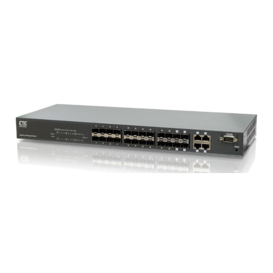
- Page 1 GSW-3420FM 20 X 100/1000Base-X SFP slots + 4 X GbE combo ports (10/100/1000Base-T or 1000Base-X) L2 managed Ethernet Switch...
- Page 2 Should the Buyer purchase or use a CTC Union product for any such unintended or unauthorized application, the Buyer shall indemnify and hold CTC Union...
- Page 3 About this manual … This manual is a general manual for different models of our Gigabit Management Fiber Optic Switch. They are similar in operation but have different hardware configurations. These models are 24 * SFP + 4 * TX(combo) ports model This model supports twenty-four SFP ports and four share TX ports.
-
Page 4: Table Of Contents
Contents 1. INTRODUCTION...................3 1.1 P ................3 ACKAGE ONTENTS 2. WHERE TO PLACE THE SWITCH............4 3. CONFIGURE NETWORK CONNECTION..........7 3.1 C ...........7 ONNECTING EVICES TO THE WITCH 3.2 C .......7 ONNECTING TO NOTHER THERNET WITCH 3.3 A ...................8 PPLICATION 4. ADDING MODULE..................9 4.1 A SFP M ................9... - Page 5 7.10 LLDP....................88 7.11 MAC T ..................91 ABLE 7.12 VLAN....................93 7.12.1 802.1Q VLAN..................93 7.12.2 Private VLANs.................96 7.12.4 Protocol-based VLAN..............98 7.12.5 IP Subnet-based VLAN..............100 7.12.6 Voice VLAN...................101 7.12.7 GVRP.....................103 7.13 Q S....................105 7.13.1 Port Ingress Classification............105 7.13.2 Port Ingress Policers..............107 7.13.3 Port and Queue Egress Shapers...........108 7.13.4 Port Egress Schedulers..............110 7.13.5 Port Egress Tag Remarking............112 7.13.6 Port DSCP Configuration.............114...
-
Page 6: Introduction
1. Introduction This Gigabit Management Fiber Optic Switch is a Layer 2 Management switch with lots of advanced network functions. Console is supported for command-line settings. Web, Telnet, and SNMP interfaces are for remote switch management through network. These functions can meet most of the management request for current network. -
Page 7: Where To Place The Switch
2. Where To Place the Switch This Switch can be placed on a flat surface (your desk, shelf or table). Place the Switch at a location with these connection considerations in mind: The switch configuration does not break the rules as specified in Section 3. ... - Page 8 [Attach Rack-Mount Brackets to the Switch] 1. Position a Rack-Mount Bracket on one side of the Switch. 2. Line up the screw holes on the bracket with the screw holes on the side of the switch. 3. Use a screwdriver to install the M3 flat head screws through the mounting bracket holes into the switch.
- Page 9 4. Repeat Step 1~3 to attach another bracket that is already attached to the switch on another side of the rack. << Safety Note for Installation >> 1. The switch shall be operated only in horizontal position. 2. If the switch works in locations, where IT power distribution system is used, double pole fusing is required in building installation.
-
Page 10: Configure Network Connection
3. Configure Network Connection 3.1 Connecting Devices to the Switch [ Connection Guidelines: ] For 10BaseT connection : Category 3 or 5 twisted-pair Ethernet cable For 100BaseTX connection : Category 5 twisted-pair Ethernet cable For 1000BaseTX connection: Category 5e or 6 twisted-pair Ethernet cable ... -
Page 11: Application
3.3 Application A switch can be used to overcome the hub-to-hub connectivity limitations as well as improve overall network performance. Switches make intelligent decisions about where to send network traffic based on the destination address of the packet. As a result, the switch can significantly reduce unnecessary traffic. The example below demonstrates the switch ability to segment the network. -
Page 12: Adding Module
4. Adding Module 4.1 Adding SFP Module This switch supports SFP (for 100/1000SX/LX/… modules) connectors for fiber optic connection. Because the SFP slots support hot-swap function, you can plug/unplug SFP transceiver to/from the SFP slot directly. The switch can auto-detect the fiber optic connection from SFP slot. S F P S l o t Follow the steps for module adding and removing. -
Page 13: Leds Conditions Definition
5. LEDs Conditions Definition The LEDs provide useful information about the switch and the status of all individual ports. [ For 24 GE Model ] STATUS CONDITION Power Switch is receiving power. Switch is power OFF. System Yellow System is running power on diagnostic. Green System is booting or running. -
Page 14: Management Connection
6. Management Connection 6.1 Console Interface and Command Line Brief 6.1.1 Console Interface Connection << Enter Console Interface >> Please follow the steps to complete the console hardware connection first. 1. Connect from console port of the switch to COM port of PC with the console cable. - Page 15 command under “(config)#”. Users with different previlege levels will have different access rights for functions of the switch. Please refer to Privilege Level Configuration of the switch. [ command line level ] After login the switch, a prompt “#” will be shown. Because this switch supports command-line for console interface, you can press “?”...
- Page 16 command can leave this mode. “interface” command has another sub-command “vlan”. IP address of the switch can be configured in this mode. ---------------------------------------------------------------- (config)# interface vlan 10 (config-if-vlan)# ---------------------------------------------------------------- << Function Keys >> Here is the function keys for console interface. [Tab] key: this key can help to get the full command keyword with just several beginning letters.
- Page 17 << Save Configuration >> Remember to do save after configuration is done with the following command. # copy running-config startup-config...
-
Page 18: Web, Telnet, And Snmp Interfaces
6.2 Web, Telnet, and SNMP Interfaces 6.2.1 Web Interface Connection Users can manage the switch with Http Web Browser connection. The default IP setting is 192.168.1.1 and NetMask 255.255.255.0. The default IP Gateway is 192.168.1.254. Before http connection, IP address configuration of the switch could be changed first. -
Page 19: Telnet And Snmp Interface Connection
Left part of the homepage is a function list. Users can select one of them for status monitoring or switch configuration. There are four operation groups in the function list. Configuration : this is for switch function configuration. Monitor : this is for switch function status and statistics monitor. Diagnostics : this is diagnostics functions for switch. - Page 20 interface is the same as console interface. << About SNMP Management Interface >> If you want to use NMS to management the switch from remote site, you have to set the IP/NetMask/Gateway address to the switch (Refer to Section 6.2.1.), and configure the SNMP setting of the switch first.
-
Page 21: Function Configuration
7. Function Configuration 7.1 Function Brief The switch supports lots of network management functions. Here are the brief of these functions. System Name, Contact, Location, Mac ID, Firmware version, Up time IP Configuration Time configuration Log configuration Port a. Speed, duplex, status, flow control, maximum packet size DHCP DHCP Snooping DHCP Relay... - Page 22 IP Multicast IP multicast profile IGMP snooping configuration MLD snooping configuration LLDP LLDP configuration 10. Mac Table Aging time, learning, secure settings. Static Mac ID assignment 11. VLAN 802.1Q VLAN configuration Private VLAN configuration Port isolation configuration Mac-based, Protocol-based, IP Subnet-based VLAN configuration Voice VLAN configuration GVRP configuration 12.
-
Page 23: System Configuration
7.2 System Configuration This function covers the following items for switch setup. Name, Contact, Location, Mac ID, Firmware version, Up time Configuration by Web : [Configuration] -> [System] -> [Information] Click “ ” at this web page to get details of the settings. Configuration by Command : System Name : (config)# hostname <word32>... - Page 24 # show version IP configuration This switch supports L3 routing function. It could be enabled at “Mode” setting. In Host mode, IP traffic between interfaces will not be routed. In Router mode traffic is routed between all interfaces. Gateway of the IP configuration is set at “IP Route”. Configuration by Web : [Configuration] ->...
-
Page 25: Time Configuration
(config)# ip route <destination_ip_addr> <netmask> <gateway_ip_addr> (config)# no ip route <destination_ip_addr> <netmask> <gateway_ip_addr> Status by Web : [Monitor] -> [System] -> [IP Status] Click “ ” at this web page to get details of the settings. Status by Command : Show IP Address : # show ip interface brief # show ipv6 interface [ vlan <vlan_list>... - Page 26 Click “ ” at this web page to get details of the settings. [Configuration] -> [System] -> [Time] Click “ ” at this web page to get details of the settings. Configuration by Command : NTP : (config)# ntp enable (config)# ntp server <1-5>...
- Page 27 Daylight Saving Time : (config)# clock summer-time <word16> date [ <1-12> <1-31> <2000-2097> <hhmm> <1-12> <1-31> <2000-2097> <hhmm> [ <1-1440> ] ] (config)# clock summer-time <word16> recurring [ <1-5> <1-7> <1-12> <hhmm> <1-5> <1-7> <1-12> <hhmm> [ <1-1440> ] ] (config)# no clock summer-time Time Zone : (config)# clock timezone <word16>...
- Page 28 Click “ ” at this web page to get details of the settings. [Monitor] -> [System] -> [Detailed Log] Click “ ” at this web page to get details of the settings. Status by Command : # show logging # show logging <1-4294967295> # show logging [ info ] [ warning ] [ error ]...
-
Page 29: Port Configuration
7.3 Port Configuration This function covers the following items for port setup. 1. Speed, Duplex, Status, Flow control, Maximum packet size Configuration by Web: [Configuration] -> [Ports] Click “?” at this web page to get details of the settings. Configuration by Command Apply the following command for configured ports first. - Page 30 Duplex : (config-if)# duplex { half | full | auto [ half | full ] } (config-if)# no duplex Flow Control : (config-if)# flowcontrol { on | off } (config-if)# no flowcontrol Maximum Frame Size : (config-if)# mtu <1518-10056> (config-if)# no mtu Status by Web : [Configuration] ->...
- Page 31 # show interface { GigabitEthernet } <port_list> capabilities Link Status: # show interface { GigabitEthernet } <port_list> status Statistics: # show interface { GigabitEthernet } <port_list> statistics [ { packets | bytes | errors | discards | filtered | { priority [<0~7> ] } } ] [{ up | down } ] # clear statistics { GigabitEthernet} <port_list>...
-
Page 32: Dhcp
7.4 DHCP This function covers the following items for DHCP functions setup. DHCP Snooping DHCP Snooping is used to block intruder on the untrusted ports of the switch device when it tries to intervene by injecting a bogus DHCP reply packet to a legitimate conversation between the DHCP client and server. - Page 33 (config)# ip dhcp snooping (config)# no ip dhcp snooping Port Setting : (config-if)# ip dhcp snooping trust (config-if)# no ip dhcp snooping trust Status by Web : [Monitor] -> [DHCP] -> [Snooping Table] Click “ ” at this web page to get details of the settings. Status by Command : # clear ip dhcp snooping statistics [ interface <port_type_list>...
- Page 34 Click “ ” at this web page to get details of the settings. Configuration by Command : Enable/Disable : (config)# ip dhcp relay (config)# no ip dhcp relay (config)# ip dhcp relay information option (config)# no ip dhcp relay information option (config)# ip dhcp relay information policy { drop | keep | replace } (config)# no ip dhcp relay information policy DHCP Relay Server :...
-
Page 35: Security Configuration
7.5 Security Configuration This function covers the following items for security setup. 7.5.1 Security for Switch Management Administrator and Privilege level configuration About the privilege level of the user... The allowed range is 1 to 15. If the privilege level value is 15, it can access all groups, i.e. - Page 36 Click “ ” at this web page to get details of the settings. Configuration by Command : Create User : (config)# username <word31> privilege <0-15> password encrypted <word4-44> (config)# username <word31> privilege <0-15> password none (config)# username <word31> privilege <0-15> password unencrypted <line31> (config)# no username <word31>...
- Page 37 Privilege Levels : [Configuration] -> [Security] -> [Switch] -> [Privilege Levels] Click “ ” at this web page to get details of the settings. Status by Command : # show users # show web privilege group [ <cword> ] level Authentication method for Console, Telnet, SSH, Http interfaces This function allows you to configure how a user is authenticated when he logs into the switch via one of the management client interfaces.
- Page 38 Click “ ” at this web page to get details of the settings. Configuration by Command : (config)# access management (config)# access management <1-16> <1-4094> <ipv4_addr> [ to <ipv4_addr> ] { [ web ] [ snmp ] [ telnet ] | all } (config)# no access management (config)# no access management <1~16>...
- Page 39 HTTPS : [Configuration] -> [Security] -> [Switch] -> [HTTPS] Click “ ” at this web page to get details of the settings. Configuration by Command : SSH : (config)# ip ssh (config)# no ip ssh HTTPS : (config)# ip http secure-redirect (config)# ip http secure-server (config)# no ip http secure-redirect (config)# no ip http secure-server...
- Page 40 Click “ ” at the web page to get details of the settings. [Configuration] -> [Security] -> [Switch] -> [SNMP] -> [Trap] Click [Add New Entry]. The following page will appear.
- Page 41 Click “ ” at the web page to get details of the settings. [Configuration] -> [Security] -> [Switch] -> [SNMP] -> [Communities] Click “ ” at the web page to get details of the settings. [Configuration] -> [Security] -> [Switch] -> [SNMP] -> [Users] Click “...
- Page 42 [Configuration] -> [Security] -> [Switch] -> [SNMP] -> [Groups] Click “ ” at the web page to get details of the settings. [Configuration] -> [Security] -> [Switch] -> [SNMP] -> [Views] Click “ ” at the web page to get details of the settings. [Configuration] ->...
- Page 43 Engine ID : (config)# snmp-server engine-id local <word10-32> (config)# no snmp-server engined-id local System Information : (config)# snmp-server host <word32> (config)# snmp-server contact <line255> (config)# snmp-server location <line255> (config)# no snmp-server host <word32> (config)# no snmp-server contact (config)# no snmp-server location Trap : (config)# snmp-server trap (config)# no snmp-server trap...
- Page 44 # show snmp # show snmp access [ <word32> { v1 | v2c | v3 | any } { auth | noauth | priv } ] # show snmp community v3 [ <word127> ] # show snmp host [ <word32> ] [ system ] [ switch ] [ interface ] [ aaa ] # show snmp security-to-group [ { v1 | v2c | v3 } <word32>...
- Page 45 [Configuration] -> [Security] -> [Switch] -> [RMON] -> [Event] Click “ ” at the web page to get details of the settings. Configuration by Command : Create an Alarm Entry : (config)# rmon alarm <1-65535> <word255> <1-2147483647> { absolute | delta } rising-threshold <-2147483648-2147483647>...
- Page 46 Click “ ” at the web page to get details of the settings. [Monitor] -> [Security] -> [Switch] -> [RMON] -> [History] Click “ ” at the web page to get details of the settings. [Monitor] -> [Security] -> [Switch] -> [RMON] -> [Alarm] Click “...
-
Page 47: Security For Network Management
7.5.2 Security for Network Management Mac ID Number Limit Control on Port configuration Limit Control allows for limiting the number of users on a given port. A user is identified by a MAC address and VLAN ID. If Limit Control is enabled on a port, the limit specifies the maximum number of users on the port. - Page 48 (config)# port-security aging (config)# port-security aging time <10-10000000> (config)# no port-security aging (config)# no port-security aging time Enable/Disable by Port : (config-if)# port-security (config-if)# no port-security Control Number and Action by Port : (config-if)# port-security maximum [ <1-1024> ] (config-if)# port-security violation { protect | trap | trap-shutdown | shutdown } (config-if)# no port-security maximum (config-if)# no port-security violation Status by Web :...
- Page 49 prevents unauthorized access to a network by requiring users to first submit credentials for authentication. One or more central servers, the backend servers, determine whether the user is allowed access to the network. These backend (RADIUS) servers are configured on the "Configuration→Security→AAA" page. The IEEE802.1X standard defines port-based operation, but non-standard variants overcome security limitations as shall be explored below.
- Page 50 (config)# dot1x guest-vlan <1-4095> (config)# dot1x max-reauth-req <1-255> (config)# dot1x guest-vlan supplicant (config)# no dot1x guest-vlan (config)# no max-reauth-req (config)# no dot1x guest-vlan supplicant For Re-authentication ... Reauthentication Enabled / Period / EAPOL Timeout / Aging Period / Hold Time : (config)# dot1x re-authentication (config)# dot1x authentication timer re-authenticate <1-3600>...
- Page 51 Click “ ” at this web page to get details of the settings. [Monitor] -> [Security] -> [Network] -> [NAS] -> [Port] Click “ ” at this web page to get details of the settings. Status by Command : # clear dot1x statistics [ interface <port_type_list> ] # show dot1x statistics { eapol | radius | all } [ interface <port_type_list>...
- Page 52 Each accessible traffic object contains an identifier to its ACL. The privileges determine whether there are specific traffic object access rights. ACL implementations can be quite complex, for example, when the ACEs are prioritized for the various situation. In networking, the ACL refers to a list of service ports or network services that are available on a host or server, each with a list of hosts or servers permitted or denied to use the service.
- Page 53 Rate Limiter Configuration : [Configuration] -> [Security] -> [Network] -> [ACL] -> [Rate Limiters] Click “ ” at this web page to get details of the settings. ACL Entry Configuration : [Configuration] -> [Security] -> [Network] -> [ACL] -> [Access Control List] Click “(+)”, the following page will appear.
- Page 54 Click “ ” at this web page to get details of the settings. Configuration by Command : Port Default Configuration : (config-if)# access-list policy <0-255> (config-if)# access-list action { permit | deny } (config-if)# access-list rate-limiter <1-16> (config-if)# access-list redirect interface { <port_type_id> | <port_type_list> } (config-if)# access-list logging (config-if)# access-list shutdown (config-if)# access-list port-state...
- Page 55 [ etype-value { <0x600-0x7ff,0x801-0x805,0x807-0x86dc,0x86de-0xffff> | any } ] | ipv4 | ipv4-icmp | ipv4-tcp | ipv4-udp | ipv6 | ipv6-icmp | ipv6-tcp | ipv6-udp } - DMAC Filter : (config)# access-list ace [ update ] <1-256> dmac-type { unicast | multicast | broadcast | any } - VLAN ID Filter : (config)# access-list ace [ update ] <1-256>...
- Page 56 Click “ ” at this web page to get details of the settings. Assign Static IP Source Guard Table : [Configuration] -> [Security] -> [Network] -> [IP Source Guard] -> [Static Table] Click “ ” at this web page to get details of the settings. Configuration by Command : Enable/Disable : (config)# ip verify source...
- Page 57 Assign Static Entry : (config)# ip source binding interface <port_type_id> <vlan_id> <ipv4_ucast> <ipv4_netmask> (config)# ip source binding interface <port_type_id> <vlan_id> <ipv4_ucast> <mac_ucast> (config)# no ip source binding interface <port_type_id> <vlan_id> <ipv4_ucast> <ipv4_netmask> (config)# no ip source binding interface <port_type_id> <vlan_id> <ipv4_ucast> <mac_ucast>...
- Page 58 Click “ ” at this web page to get details of the settings. Specify ARP Inspection is enabled on which VLAN : [Configuration] -> [Security] -> [Network] -> [ARP Inspection] -> [VLAN Configuration] Click “ ” at this web page to get details of the settings. Assign Static ARP Inspection Entry : [Configuration] ->...
- Page 59 Click “ ” at this web page to get details of the settings. Show Dynamic ARP Inspection Table : [Configuration] -> [Security] -> [Network] -> [ARP Inspection] -> [Dynamic Table] Click “ ” at this web page to get details of the settings. Configuration by Command : Clear ARP cache : # clear ip arp...
- Page 60 [Monitor] -> [Security] -> [Network] -> [ARP Inspection] Click “ ” at this web page to get details of the settings. Status by Command : # show ip arp # show ip arp inspection [ interface <port_type_list> | vlan <vlan_list> ] # show ip arp inspection entry [ dhcp-snooping | static ] [ interface <port_type_list>...
-
Page 61: Security For Aaa Server Configuration
7.5.3 Security for AAA Server Configuration RADIUS Server configuration RADIUS is an acronym for Remote Authentication Dial In User Service. It is a networking protocol that provides centralized access, authorization and accounting management for people or computers to connect and use a network service. - Page 62 <1-1000> ] [ key <line1-63> ] (config)# no radius-server host { <word1-255> | <ipv4_ucast> | <ipv6_ucast> } [ auth-port <0-65535> ] [ acct-port <0-65535> ] Status by Web : [Monitor] -> [Security] -> [AAA] -> [RADIUS Overview] Click “ ” at this web page to get details of the settings. [Monitor] ->...
- Page 63 # show radius-server [ statistics ] TACACS+ Server configuration TACACS+ is an acronym for Terminal Acess Controller Access Control System Plus. It is a networking protocol which provides access control for routers, network access servers and other networked computing devices via one or more centralized servers.
- Page 64 Status by Command : # show tacacs-server...
-
Page 65: Aggregation
7.6 Aggregation Port Aggregation(Link Aggregation) uses multiple ports in parallel to increase the link speed beyond the limits of a port and to increase the redundancy for higher availability. Static Configuration by Web : [Configuration] -> [Aggregation] -> [Static] Click “ ”... - Page 66 LACP Configuration by Web : [Configuration] -> [Aggregation] -> [LACP] Click “ ” at this web page to get details of the settings. Configuration by Command : System Priority : (config)# lacp system-priority <1-65535> (config)# no lacp system-priority <1-65535> LACP Port Configuration : (config-if)# lacp (config-if)# lacp key { <1-65535>...
- Page 67 [Monitor] -> [LACP] -> [Port Status] Click “ ” at this web page to get details of the settings. [Monitor] -> [LACP] -> [Port Statistics] Click “ ” at this web page to get details of the settings. Status by Command : # clear lacp statistics # show lacp { internal | statistics | system-id | neighbour }...
-
Page 68: Loop Protection
7.7 Loop Protection This function is used to configure Loop Protection function. Loop on port will cause packet storm in switch. If Loop Protection is enabled on ports and Tx Mode is enabled, the port is actively generating loop protection PDU's. If loopback is found, the action could be shutdown port or log it. - Page 69 (config)# no loop-protect shutdown-time Port Loop Protection Enable/Disable : (config-if)# loop-protect (config-if)# no loop-protect Port Action if loop detected : (config-if)# loop-protect action { [ shutdown ] [ log ] } (config-if)# no loop-protect action Port Actively Generate PDUs (config-if)# loop-protect tx-mode (config-if)# no loop-protect tx-mode Status by Web : [Monitor] ->...
-
Page 70: Spanning Tree
7.8 Spanning Tree Spanning tree is a protocol to prevent network loop in network topology. If network loop happens, it will cause the network unstable because more and more traffic will loop in the network. If network loop happens, spanning tree protocol will block one connection in the loop automatically. - Page 71 Max Age : (config)# spanning-tree mst max-age <6-40> [ forward-time <4-30> ] (config)# no spanning-tree mst max-age Maximum Hop Count : (config)# spanning-tree mst max-hops <6-40> (config)# no spanning-tree mst max-hops Transmit Hold Count : (config)# spanning-tree transmit hold-count <1-10> (config)# no spanning-tree transmit hold-count Edge Port BPDU Filtering : (config)# spanning-tree edge bpdu-filter...
- Page 72 Click “ ” at this web page to get details of the settings. Status by Command : # show spanning-tree summary # show spanning-tree active # show spanning-tree mst MSTI Configuration - VLAN Mapping Configuration by Web : [Configuration] -> [Spanning Tree] -> [MSTI Mapping] Click “...
- Page 73 Configuration by Command : Configuration Identification : (config)# spanning-tree mst name <word32> revision <0-65535> (config)# no spanning-tree mst name MSTI VLAN Mapping : (config)# spanning-tree mst <0-7> vlan <vlan_list> (config)# no spanning-tree mst <0-7> vlan Status by Web : [Configuration] -> [Spanning Tree] -> [MSTI Mapping] Click “...
- Page 74 STP CIST Port Configuration Configuration by Web : [Configuration] -> [Spanning Tree] -> [CIST Ports] Click “ ” at this web page to get details of the settings. Configuration by Command : Enable/Disable on Port : (config-if)# spanning-tree (config-if)# no spanning-tree Path Cost : (config-if)# spanning-tree mst <0-7>...
- Page 75 (config-if)# spanning-tree bpdu-guard (config-if)# no spanning-tree bpdu-guard Point-to-Point : (config-if)# spanning-tree link-type { point-to-point | shared | auto } (config-if)# no spanning-tree link-type Status by Web : [Monitor] -> [Spanning Tree] -> [Port Status] Click “ ” at this web page to get details of the settings. [Monitor] ->...
- Page 76 Click “ ” at this web page to get details of the settings. Configuration by Command : Path Cost : (config-if)# spanning-tree mst <0-7> cost { <1-200000000> | auto } (config-if)# no spanning-tree mst <0-7> cost Port Priority : (config-if)# spanning-tree mst <0-7> port-priority <0-240> (config-if)# no spanning-tree mst <0-7>...
-
Page 77: Ip Multicast
7.9 IP Multicast IP multicast is a method of sending Internet Protocol (IP) datagrams to a group of interested receivers in a single transmission. It is often employed for streaming media applications on the Internet and private networks. 7.9.1 IP Multicast Profile Profile Table IPMC Profile is an acronym for IP MultiCast Profile. - Page 78 Edit/Delete IP Multicast Profile Rule : (config-ipmc-profile)# range <word16> { permit | deny } [ log ] [ next <word16> ] (config-ipmc-profile)# no range <word16> “<word16>” is the name of Address Entry. Edit/Delete Description of Profile : (config-ipmc-profile)# description <line64> (config-ipmc-profile)# no description <line64>...
-
Page 80: Mvr
7.9.2 MVR The MVR feature enables multicast traffic forwarding on the Multicast VLANs. In a multicast television application, a PC or a network television or a set-top box can receive the multicast stream. Multiple set-top boxes or PCs can be connected to one subscriber port, which is a switch port configured as an MVR receiver port. - Page 81 (config)# mvr name <word16> frame priority <0-7> (config)# mvr name <word16> frame tagged (config)# mvr name <word16> igmp-address <ipv4_ucast> (config)# mvr name <word16> last-member-query-interval <0-31744> (config)# mvr name <word16> mode { dynamic | compatible } (config)# no mvr vlan <vlan_list> (config)# no mvr vlan <vlan_list>...
- Page 82 Click “ ” at this web page to get details of the settings. Status by Command : # show mvr [ vlan <vlan_list> | name <word16> ] [ group-database [ interface <port_type_list> ] [ sfm-information ] ] [ detail ] # clear mvr [ vlan <vlan_list>...
-
Page 83: Ip Multicast
7.9.3 IP Multicast IGMP Snooping IGMP is an acronym for Internet Group Management Protocol. It is a communications protocol used to manage the membership of Internet Protocol multicast groups. IGMP is used by IP hosts and adjacent multicast routers to establish multicast group memberships. - Page 84 Click “ ” at this web page to get details of the settings. IGMP Snooping Port Filtering Profile : [Configuration] -> [IPMC] -> [IGMP Snooping] -> [Port Filtering Profile] Click “ ” at this web page to get details of the settings. Note: After Profile is selected, clicking the “eye”...
- Page 85 (config-if)# no ip igmp snooping mrouter - Immediate-Leave Enable/Disable : (config-if)# ip igmp snooping immediate-leave (config-if)# no ip igmp snooping immediate-leave - Throttling(Max. Group Number) : (config-if)# ip igmp snooping max-groups <1-10> (config-if)# no ip igmp snooping max-groups IGMP Snooping VLAN Configuration : - Assign VLAN for IGMP Snooping : (config)# ip igmp snooping vlan <vlan_list>...
- Page 86 Click “ ” at this web page to get details of the settings. [Monitor] -> [IPMC] -> [IGMP Snooping] -> [Groups Information] Click “ ” at this web page to get details of the settings. [Monitor] -> [IPMC] -> [IGMP Snooping] -> [IPv4 SFM Information] Click “...
- Page 87 to those ports that want to receive it. Configuration by Web : Global Basic and Port Related Configuration : [Configuration] -> [IPMC] -> [MLD Snooping] -> [Basic Configuration] Click “ ” at this web page to get details of the settings. MLD Snooping VLAN Configuration : [Configuration] ->...
- Page 88 Click “ ” at this web page to get details of the settings. Note: After Profile is selected, clicking the “eye” icon will show the profile content. Configuration by Command : MLD Snooping Basic Configuration : - Snooping Enable/Disable : (config)# ipv6 mld snooping (config)# no ipv6 mld snooping - Unregistered IPMCv6 Flooding Enable/Disable :...
- Page 89 (config-if-vlan)# ipv6 mld snooping query-interval <1-31744> (config-if-vlan)# ipv6 mld snooping query-max-response-time <0-31744> (config-if-vlan)# ipv6 mld snooping robustness-variable <1-255> (config-if-vlan)# ipv6 mld snooping unsolicited-report-interval <0-31744> (config-if-vlan)# no ipv6 mld snooping (config-if-vlan)# no ipv6 mld snooping compatibility (config-if-vlan)# no ipv6 mld snooping last-member-query-interval (config-if-vlan)# no ipv6 mld snooping priority (config-if-vlan)# no ipv6 mld snooping querier election (config-if-vlan)# no ipv6 mld snooping query-interval...
- Page 90 Click “ ” at this web page to get details of the settings. Status by Command : # clear ipv6 mld snooping [ vlan <vlan_list> ] statistics # show ipv6 mld snooping [ vlan <vlan_list> ] [ group-database [ interface <port_type_list>...
-
Page 91: Lldp
7.10 LLDP LLDP is an IEEE 802.1ab standard protocol. The Link Layer Discovery Protocol(LLDP) specified in this standard allows stations attached to an IEEE 802 LAN to advertise, to other stations attached to the same IEEE 802 LAN, the major capabilities provided by the system incorporating that station, the management address or addresses of the entity or entities that provide management of those capabilities, and the identification of the stations point of attachment to the IEEE 802 LAN required by those management entity or... - Page 92 (config)# no lldp transmission-delay - Tx Reinit : (config)# lldp reinit <1-10> (config)# no lldp reinit Port Configuration : - Enable/Disabled transmision of LLDP frames : (config-if)# lldp transmit (config-if)# no lldp transmit - Enable/Disable decoding of received LLDP frames : (config-if)# lldp receive (config-if)# no lldp receive - Optional TLVs to transmit :...
- Page 93 Status by Command : # clear lldp statistics # show lldp neighbors [ interface <port_type_list> ] # show lldp statistics [ interface <port_type_list> ]...
-
Page 94: Mac Table
7.11 MAC Table Switching of frames is based upon the DMAC address contained in the frame. The switch builds up a table that maps MAC addresses to switch ports for knowing which ports the frames should go to ( based upon the DMAC address in the frame ). - Page 95 MAC Address Learning on Port : (config-if)# mac address-table learning (config-if)# no mac address-table learning MAC Address Secure on Port : (config-if)# mac address-table learning secure (config-if)# no mac address-table learning secure Status by Web : [Monitor] -> [MAC Table] Click “...
-
Page 96: Vlan
7.12 VLAN VLAN(Virtual LAN) is a method to restrict communication between switch ports. At layer 2, the network is partioned into multiple, distinct, mutually isolated broadcast domains. This switch supports 802.1Q VLAN, Private VLAN, MAC-based VLAN, Protocol-based VLAN, IP Subnet-based VLAN, and Voice VLAN for different VLAN applications. - Page 97 (config)# no vlan ethertype s-custom-port <0x0600-0xffff> Port VLAN Configuration : - Port Mode : (config-if)# switchport mode { access | trunk | hybrid } (config-if)# no switchport mode - Port VLAN ID : If port is in Access mode, ... (config-if)# switchport access vlan <vlan_id>...
- Page 98 (config-if)# switchport forbidden { add | remove } { { vid <vlan_id> } | { name <word> } } (config-if)# no switchport forbidden vlan Status by Web : [Monitor] -> [VLANs] -> [Membership] Click “ ” at this web page to get details of the settings. [Monitor] ->...
-
Page 99: Private Vlans
7.12.2 Private VLANs In a private VLAN, PVLANs provide layer 2 isolation between ports within the same broadcast domain. Isolated ports configured as part of PVLAN cannot communicate with each other. Member ports of a PVLAN can communicate with each other. Configuration by Web : Create/Edit Private VLAN : [Configuration] ->... - Page 100 7.12.3 MAC-based VLAN As a way of grouping VLAN members, MAC address-based VLAN (MAC-based VLAN) decides the VLAN for forwarding an untagged frame based on the source MAC address of the frame. Configuration by Web : [Configuration] -> [VCL] -> [MAC-based VLAN] Click “...
-
Page 101: Protocol-Based Vlan
7.12.4 Protocol-based VLAN With protocol-based VLAN membership, computers are assigned to VLANs by using the protocol that is in use. For example, this method enables an Internetwork Packet Exchange (IPX) network or Internet Protocol (IP) network to have its own VLAN. Configuration by Web : Create/Delete Protocol to Group Mapping : [Configuration] ->... - Page 102 # show vlan protocol [ eth2 { <0x600-0xffff> | arp | ip | ipx | at } ] [ snap { <0x0-0xffffff> | rfc_1042 | snap_8021h } <0x0-0xffff> ] [ llc <0x0-0xff> <0x0-0xff> ]...
-
Page 103: Ip Subnet-Based Vlan
7.12.5 IP Subnet-based VLAN In an IP subnet-based VLAN, all the end workstations in an IP subnet are assigned to the same VLAN. In this VLAN, users can move their workstations without reconfiguring their network addresses. IP subnet VLANs are based on Layer 3 information from packet headers. -
Page 104: Voice Vlan
7.12.6 Voice VLAN Voice VLAN is VLAN configured specially for voice traffic. By adding the ports with voice devices attached to voice VLAN, we can perform QoS-related configuration for voice data, ensuring the transmission priority of voice traffic and voice quality. Configuration by Web : Voice VLAN Configuration : [Configuration] ->... - Page 105 Configuration by Command : Enable/Disable : (config)# voice vlan (config)# no voice vlan VLAN ID : (config)# voice vlan vid <vlan_id> (config)# no voice vlan vid Aging Time : (config)# voice vlan aging-time <10-10000000> (config)# no voice vlan aging-time Traffic Class : (config)# voice vlan class { <0-7>...
-
Page 106: Gvrp
7.12.7 GVRP GVRP (GARP VLAN Registration Protocol or Generic VLAN Registration Protocol) is a protocol that facilitates control of virtual local area networks (VLANs) within a larger network . GVRP conforms to the IEEE 802.1Q specification, which defines a method of tagging frames with VLAN configuration data. - Page 107 Enable/Disable GVRP : (config)# gvrp (config)# no gvrp Max. VLAN Number : (config)# gvrp max-vlans <1-4095> (config)# no gvrp max-vlans <1-4095> GVRP Time Intervals : (config)# gvrp time { [ join-time <1-20> ] [ leave-time <60-300> ] [ leave-all-time <1000-5000> ] }*1 (config)# no gvrp time { [ join-time <1-20>...
-
Page 108: Qos
7.13 QoS QoS is an acronym for Quality of Service. It is a method to guarantee a bandwidth relationship between individual applications or protocols. A communications network transports a multitude of applications and data, including high-quality video and delay-sensitive data such as real-time voice. Networks must provide secure, predictable, measurable, and sometimes guaranteed services. - Page 109 (config-if)# qos cos <0-7> (config-if)# no qos cos Port Ingress DPL : (config-if)# qos dpl <dpl> (config-if)# no qos dpl Enable/Disable DSCP QoS on Port : (config-if)# qos trust dscp (config-if)# no qos trust dscp Status by Web : [Configuration] -> [QoS] -> [Port Classification] Click “...
-
Page 110: Port Ingress Policers
7.13.2 Port Ingress Policers This setting is used to configure Port Ingress Rate Limit. If flow control is enabled and the port is in flow control mode, then pause frames are sent instead of discarding frames when limit rate is reached Configuration by Web : [Configuration] ->... -
Page 111: Port And Queue Egress Shapers
7.13.3 Port and Queue Egress Shapers This setting will show egress shaper settings of each port and each queue. Click Port number to configure its Egress Shaper. Configuration by Web : [Configuration] -> [QoS] -> [Port Shaping] Click port number, port and queue egress scheduler and shapers setting page will appear. - Page 112 give a limit value Click “ ” at this web page to get details of the settings. Configuration by Command : Port Egress Shaper : (config-if)# qos shaper <uint> (config-if)# no qos shaper Queue Egress Shaper of Port : (config-if)# qos queue-shaper queue <0~7> <uint> [ excess ] (config-if)# no qos queue-shaper queue <0~7>...
-
Page 113: Port Egress Schedulers
7.13.4 Port Egress Schedulers This setting will show port egress scheduler mode and weight of each queue. Click Port number to configure its Egress Scheduler. Configuration by Web : [Configuration] -> [QoS] -> [Port Scheduler] Click port number, port and queue egress scheduler and shapers setting page will appear. - Page 114 give a limit value Click “ ” at this web page to get details of the settings. Configuration by Command : Weighting of Queue for WRR : (config-if)# qos wrr <1-100> <1-100> <1-100> <1-100> <1-100> <1-100> (config-if)# no qos wrr Status by Web : [Configuration] ->...
-
Page 115: Port Egress Tag Remarking
7.13.5 Port Egress Tag Remarking This setting is used to show Egress Tag Remarking mode of each port. The mode could be ... - Classified: Use classified PCP/DEI values. - Default: Use default PCP/DEI values. - Mapped: Use mapped versions of QoS class and DP level. Click Port number to configure the Egress Tag Remarking mode for it. - Page 116 Click “ ” at this web page to get details of the settings. Configuration by Command : Default PCP and DEI setting : (config-if)# qos tag-remark pcp <0-7> dei <0-1> (config-if)# no qos tag-remark Map PCP and DEI setting : (config-if)# qos tag-remark mapped [ yellow <0-4>...
-
Page 117: Port Dscp Configuration
7.13.6 Port DSCP Configuration This page allows you to configure the basic QoS Port DSCP Configuration settings for all switch ports. You can configure DSCP ingress and egress settings. In Ingress settings you can change ingress translation and classification settings for individual ports. In egress settings, you can configure Rewriting or Remapping for individual ports. - Page 118 Click “ ” at this web page to get details of the settings. Configuration by Command : Ingress DSCP Translate Enable/Disable : (config-if)# qos dscp-translate (config-if)# no qos dscp-translate Ingress Classify DSCP values : (config-if)# qos dscp-classify { zero | selected | any } (config-if)# no qos dscp-classify Egress DSCP Rewrite : : (config-if)# qos dscp-remark { rewrite | remap | remap-dp }...
-
Page 119: Dscp To Internal Priority Mapping (Ingress)
7.13.7 DSCP to Internal Priority Mapping (Ingress) This setting is used to configure QoS Ingress Classification for each DSCP value. Only frames with trusted DSCP values are mapped to a specific QoS class and Drop Precedence Level. Frames with untrusted DSCP values will not be applied. Configuration by Web : [Configuration] ->... -
Page 120: Dscp Ingress Translation And Egress Remap
7.13.8 DSCP Ingress Translation and Egress Remap This setting is used to configure the QoS DSCP Translation settings for all DSCP values. DSCP translation can be done in Ingress or Egress. Ingress side DSCP can be first translated to new DSCP before using the DSCP for QoS class and DPL map. - Page 121 Status by Web : [Configuration] -> [QoS] -> [DSCP Translation] Click “ ” at this web page to get details of the settings. Status by Command : Ingress DSCP values translation mapping : # show qos maps dscp-ingress-translation DSCP values selected for ingress classify : # show qos maps dscp-classify Egress DSCP values translation mapping : # show qos maps dscp-egress-translation...
-
Page 122: Internal Priority To Dscp Mapping (Egress)
7.13.9 Internal Priority to DSCP Mapping (Egress) This setting is used to configure the mapping of QoS class to internal DSCP value. Frames got a QoS class (either from port default or VLAN Tag or DSCP) then it can map this QoS to internal DSCP. This internal DSCP then can do another egress map to affect the DSCP value when the frame is sent out. -
Page 123: Qos Control List
7.13.10 QoS Control List QCL is an acronym for QoS Control List. It is the list table of QCEs, containing QoS control entries that classify to a specific QoS class on specific traffic objects. Each accessible traffic object contains an identifier to its QCL. The privileges determine specific traffic object to specific QoS class. - Page 124 - Setup action : (config)# qos qce <1-256> action { [ cos { <0-7> | default } ] [ dpl { <0-1> | default } ] [ dscp { <0-63> | <dscp> | default } ] - Place QCE before the next QCE ID (config)# qos qce <1-256>...
-
Page 125: Port Storm Control
7.13.11 Port Storm Control This setting allows you to configure the storm control settings for all switch ports. There is a storm rate control for unicast frames, broadcast frames and unknown (flooded) frames. Configuration by Web : [Configuration] -> [QoS] -> [Storm Control] Click “... -
Page 126: Weighted Random Early Detection Configuration
7.13.12 Weighted Random Early Detection Configuration Weighted random early detection (WRED) is a queueing discipline for a network scheduler suited for congestion avoidance. It is an extension to random early detection (RED) where a single queue may have several different queue thresholds. -
Page 127: Port Mirroring
7.14 Port Mirroring For debugging network problems or monitoring network traffic, the switch system can be configured to mirror frames from multiple ports to a mirror port. (In this context, mirroring a frame is the same as copying the frame.) Both incoming (source) and outgoing (destination) frames can be mirrored to the mirror port. -
Page 128: Sflow
7.15 sFlow sFlow is an industry standard technology for monitoring switched networks through random sampling of packets on switch ports and time-based sampling of port counters. The sampled packets and counters (referred to as flow samples and counter samples, respectively) are sent as sFlow UDP datagrams to a central network traffic monitoring server. - Page 129 (config)# no sflow timeout [ receiver <range_list> ] - Max. Datagram Size (config)# sflow max-datagram-size [ receiver <range_list> ] <200-1468> (config)# no sflow max-datagram-size [ receiver <range_list> ] Configuration on Port : - Counter Poller : (config-if)# sflow counter-poll-interval [ sampler <range_list> ] [ <1-3600> ] (config-if)# no sflow counter-poll-interval [ <range_list>...
-
Page 130: Diagnostics
7.16 Diagnostics This switch supports network connection diagnostics by ping test and TX port cable connection test. Configuration by Web : Ping by IPv4 : [Configuration] -> [Diagnostics] -> [Ping] Click “ ” at this web page to get details of the settings. Ping by IPv6 : [Configuration] ->... - Page 131 Configuration by Command : Ping by IPv4 : # ping ip <word1-255> [ repeat <1-60> ] [ size <2-1452> ] [ interval <0-30> ] Ping by IPv6 : # ping ipv6 <ipv6_addr> [ repeat <1-60> ] [ size <2-1452> ] [ interval <0-30> ] [ interface vlan <vlan_id>...
-
Page 132: Maintenance
7.17 Maintenance The maintenance functions for the switch include system reboot, software update/select, configuration backup/restore/factory default. Configuration by Web : System Reboot : [Configuration] -> [Maintenance] -> [Restart Device] Click “ ” at this web page to get details of the settings. Factory Default : [Configuration] ->... - Page 133 Click “ ” at this web page to get details of the settings. Configuration : - Save running-config to startup-config : [Configuration] -> [Maintenance] -> [Configuration] -> [Save startup-config] Click “ ” at this web page to get details of the settings. - Configuration Download : [Configuration] ->...
- Page 134 Click “ ” at this web page to get details of the settings. - Configuration Activate : [Configuration] -> [Maintenance] -> [Configuration] -> [Activate] Click “ ” at this web page to get details of the settings. - Configuration Delete : [Configuration] ->...
- Page 135 Software Upload : # firmware upgrade <tftp://server/path-and-filename> Software Image Select : # firmware swap Configuration : - Save running-config to startup-config : # copy running-config startup-config - Configuration Download : # copy { startup-config | running-config } <tftp://server/path-and-filename> [ syntax-check ] - Configuration Upload : # copy <tftp://server/path-and-filename>...
- Page 136 Click “ ” at this web page to get details of the settings. Software Image Select : [Configuration] -> [Maintenance] -> [Software] -> [Image Select] Click “ ” at this web page to get details of the settings. Configuration : - Save running-config to startup-config : [Configuration] ->...
-
Page 137: Software Update And Backup
8. Software Update and Backup This switch supports software update and configuration backup/restore functions. It could be done in two ways. 1. From web browser: Doing by http protocol and by web browser. Please refer to the description of “Maintenance” function in Section 7.17 for Software Update and Configuration Backup/Restore. -
Page 138: Product Hardware Specifications
A. Product Hardware Specifications [ 24SFP+4TX(combo) Model ] Access Method Ethernet, CSMA/CD Standards Conformance IEEE 802.3 10BASE-T, IEEE 802.3u 100BASE IEEE 802.3z, IEEE 802.3ab (1000Base) Communication Rate 10/100/1000Mbps for TX, Full / Half duplex (auto-negotiation) 100/1000Mbps for SFP TX MDI/MDIX Auto-Detect Indicator Panel LEDs for each unit : Power, System... - Page 139 Console D-Sub 9 Dimensions 440 x 172 x 44 mm Certification CE Mark, FCC Class A Temperature Standard Operating: 0 to 50℃ Humidity 10% to 90% (Non-condensing) Bridging Function Filtering, forwarding and learning Switching Method Store-and-forward Address Table 16K entries Filtering/Forwarding Rate Line speed Maximum Packet Size 10056 Bytes...
-
Page 140: Product Software Specifications
B. Product Software Specifications Port Control Port speed, duplex mode, and flow control Port Auto MDI/MDI-X Port frame size (jumbo frames), Maximum ingress frame size (10056 bytes) Port state (administrative status) Port status (link monitoring) Port statistics (MIB counters) L2 Switching Auto MAC address learning/aging and MAC addresses (static) DHCP snooping... - Page 141 Security Port-Based 802.1X, Single 802.1X, Multiple 802.1X, MAC-Based Authentication VLAN Assignment , QoS Assignment, Guest VLAN RADIUS Accounting MAC Address Limit IP MAC binding, IP/MAC binding dynamic to static TACACS+ Web & CLI Authentication Authorization (15 user levels) ACLs for filtering/policing/port copy IP source guard Synchronization NTPv4 Client...
-
Page 142: Compliances
C. Compliances EMI Certification FCC Class A Certification (USA) Warning: This equipment generates, uses, and can radiate radio frequency energy and, if not installed and used in accordance with the instruction manual, may cause interference to radio communications. It has been tested and found to comply with the limits for a Class A digital device pursuant to Subpart B of Part 15 of FCC Rules, which are designed to provide reasonable protection against such interference when operated in a commercial environment. -
Page 143: Warranty
D. Warranty We warrant to the original owner that the product delivered in this package will be free from defects in material and workmanship for a period of warranty time from the date of purchase from us or the authorized reseller. The warranty does not cover the product if it is damaged in the process of being installed.
Need help?
Do you have a question about the GSW-3420FM and is the answer not in the manual?
Questions and answers