Advertisement
Quick Links
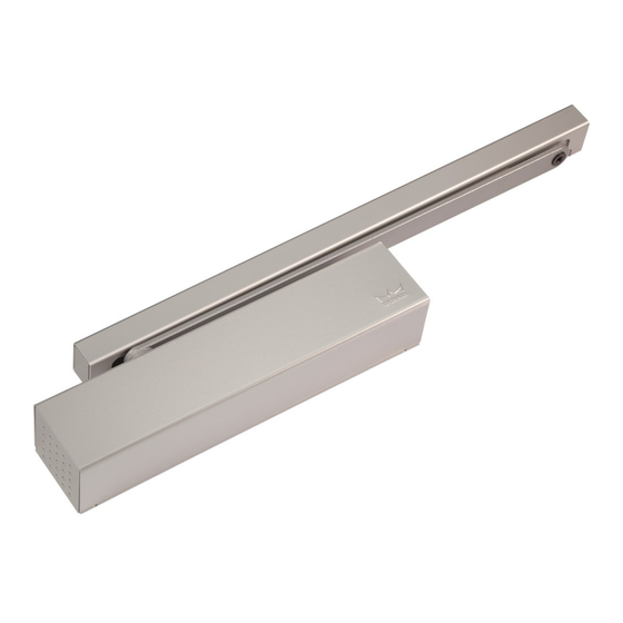
TS93 GSR/EMF PT
ATTENTION!!!
Before you begin, determine installation type (RIGHT HAND ACTIVE OR INACTIVE).
Door coordinator suitable for door from 59" to 98" in width. Inactive door width in the case of unequal doors
is a 23" minimum. Also, you will need the tools listed below.
LEFT HAND INACTIVE
LEFT HAND ACTIVE
Tool List:
Tape Measure
#10-32 Tap & Holder
Center Punch & Hammer
1/2" Box Wrench
3/16" Slotted Driver
10" Adjustable Wrench
INSTRUCTIONS
No. 21 (.159") & 1/8" Drill Bits and Drill
#2 Cross-Point Screw Driver
2.5mm, 3mm & 5mm Hex Wrench (supplied)
RIGHT HAND ACTIVE
RIGHT HAND INACTIVE
Hacksaw
08281031
INS NO:
1 of 11
09/11
PAGE:
REV:
Advertisement

Related Manuals for Dorma TS93 GSR/EMF


Summary of Contents for Dorma TS93 GSR/EMF
- Page 1 INSTRUCTIONS TS93 GSR/EMF PT ATTENTION!!! Before you begin, determine installation type (RIGHT HAND ACTIVE OR INACTIVE). Door coordinator suitable for door from 59” to 98” in width. Inactive door width in the case of unequal doors is a 23” minimum. Also, you will need the tools listed below.
- Page 2 TS93 GSR EMF PT CAUTION: Sex nuts are required for attachment of components to unreinforced, wood or plastic faced com- posite type fire doors, unless an alternative method is identified in the individual door manufacture’s listings. Make sure door efficiently operates prior to installing the closer. When Installing main arm, observe direc- tions closely.
- Page 3 TS93 GSR EMF PT Attach active track assembly with two M5 flat head machine screws, be sure to insert the end cap as shown below. Attach the Inactive Track Assembly with two M5 Flat Head Machine Screws, be sure to insert the end cap. The following de- scribes the process for a left-handed active leaf.
- Page 4 TS93 GSR EMF PT Place wrench on bottom of pinion square and rotate approximately 5 degrees as shown. With the main arm parallel to the door. Place the main arm hub on to the top pinion square and fasten securely with pinion screw. Hex Key Track Arm M6 Socket Head Screw...
-
Page 5: Side View
TS93 GSR EMF PT Close both door leaves. Press lever with roller against the door (A) and tighten the hex screw (B). Remove Alignment screw (C). DOOR SIDE VIEW ROLLER Mark and cut the length of the connecting channel as shown. In doing so, it will ensure that the plastic guide element is pushed up against the slide shoe, and the trigger dial has been fully turned in (clockwise). -
Page 6: Wiring Diagram
TS93 GSR EMF PT The clamping rod will only operate smoothly if the clamping Close both door leaves. Unwind the trigger dial (counter clockwise) plate has been properly adjusted. Only then will the active by hand until the pin drops out. The active door will starts to close. leaf swing freely with the inactive leaf closed. - Page 7 TS93 GSR EMF PT CAUTION: DO NOT REMOVE VALVE!!! Adjust sweep (S), latch (L), backcheck (BC) and delay action (DA) valves. Adjust Sweep (S), Latch (L) valves. DECREASE SPEED INCREASE SPEED Adjust Backcheck (BC) and delay action (DA) valves. DECREASE (BC INTENSITY) INCREASE (DA TIME)
- Page 8 TS93 GSR EMF PT Setting the hold open point. Open the door leaf ` until engaged in hold open. If another degree of hold open is desired, loosen adjustment screws. Slide the electric hold open assembly in the appropriate direction for an increased or decreased degree of hold open and retighten adjustment screws.
- Page 9 TS93 GSR EMF PT GSR/EMF - ACTIVE DOOR HOLD OPEN ONLY or ACTIVE & INACTIVE DOOR HOLD OPEN TOGETHER Incorporates an electric hold open device in both leaves. This enables both leaves to be held open when inactive leaf is placed in the pre- selected hold open position and also enables the active leaf to be held open independently when the inactive leaf is in the closed position.
- Page 10 TS93 GSR EMF PT INSTALL END CAP TRIM AND COVERS Clip on end cap trims. Break out marked recess in the active and inactive leaf track cover and clip cover into position ACTIVE LEAF COVER INACTIVE LEAF COVER End cap trim JOINTING INSTALL CENTER COVER AND CENTER CAPS...
- Page 11 A carry bar must be installed to insure that the active door is opened far enough for the inactive door to close. DORMA carry bar MK-398 (3’-6” and wider door) is required! Installation instructions are included with the carry bar.
Need help?
Do you have a question about the TS93 GSR/EMF and is the answer not in the manual?
Questions and answers