DMP Electronics 7800 Series Installation And Programming Manual
Graphic touchscreen keypad
Hide thumbs
Also See for 7800 Series:
- Installation and programming manual (60 pages) ,
- Quick start manual (2 pages) ,
- Installation and programming manual (26 pages)

Related Manuals for DMP Electronics 7800 Series


Summary of Contents for DMP Electronics 7800 Series
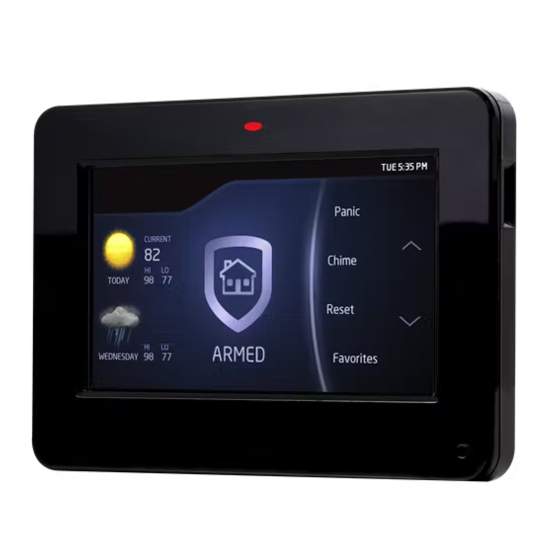
- Page 1 7800 Series Graphic Touchscreen Keypad INSTALLATION AND PROGRAMMING GUIDE System Armed Panic CURRENT Chime 98 77 98 77 TODAY Reset ARMED Favorites 85 68 WEDNESDAY MON 5:35 PM MON 5:35 PM...
-
Page 3: Table Of Contents
TABLE OF CONTENTS About the Keypad ......1 Additional Programming .... 29 Update the Keypad ........... 30 Keypad Features ......2 Programmable Carousel Menu .......3 Test the Keypad ......31 Enter Characters ......4 End User Training ......32 Arm and Disarm the System ......32 Install the Keypad ......6 Use Access Control ..........34 Remove the Cover ..........6... -
Page 5: About The Keypad
ABOUT THE KEYPAD 7800 Series Graphic Touchscreen Keypads offer flexible features and functionality. Each keypad provides optional panic keys, an AC Power/Armed LED, an internal speaker, a simple terminal connection to a 4-wire keypad bus, and optional backboxes for conduit or wall-mount applications. -
Page 6: Keypad Features
Navigation Arrows CURRENT or touch and drag Chime the menu to scroll 98 77 98 77 TODAY Reset Local Weather ARMED Favorites 85 68 WEDNESDAY MON 5:35 PM MON 5:35 PM Figure 1: Keypad Features 7800 Series Installation and Programming Guide... -
Page 7: Programmable Carousel Menu
In Menu to select that option to display in the carousel menu. Press that box again to deselect that option. See Figure 2. MODEL NUMBER 7800 V110 0961017 Display In Menu Brightness Chime Tone Reset Easy Exit Volume Check In Figure 2: Keypad Options 7800 Series Installation and Programming Guide... -
Page 8: Enter Characters
Press ABC to enter uppercase letters. • Press abc to enter lowercase letters. • Press !@# to enter special characters. • Press 123 to enter numbers and to return to the number pad. See Figure 4. • 7800 Series Installation and Programming Guide... - Page 9 Return to Home Screen Select Areas Special Characters ENTER CODE: Uppercase/ Lowercase Letters Number Pad Figure 3: Number Pad Figure 4: Standard Keyboard 7800 Series Installation and Programming Guide...
-
Page 10: Install The Keypad
Base screwdriver upward. Repeat with the other slot. Separate the cover from the base and set the cover containing the keypad components aside. See Figure 5. Figure 5: Separate the Keypad Housing 7800 Series Installation and Programming Guide... -
Page 11: Wire The Keypad
• Zone 1: Brown White/White Brown • Zone 2: Red White/White Red (Zone 2 Bypass) • Zone 3: Orange White/White Orange (REX) • Zone 4: Yellow White/White Yellow 7800 Series Installation and Programming Guide... - Page 12 White – Connect Reader Data 1 1K EOL Red – Keypad Power Green/White – Connect Reader Data 0 Black Black – Ground Green Yellow Red – Keypad Power Figure 6: Keypad Back Showing Wiring Assignments 7800 Series Installation and Programming Guide...
-
Page 13: Wire For Access Control
Connect the Data 1 (reader) wire to the white wire on the 5–wire keypad cable. Connect the Data 0 (reader) wire to the green/white wire on the 5–wire keypad cable. See Figure 7. 7800 Series Installation and Programming Guide... - Page 14 1K EOL Z1 + Zone 1 (7/0 Panic) Black – Ground Green – Receive Data Yellow – Send Data Red – Keypad Power External Card Reader To Panel Keypad Bus Figure 7: Access Control Wiring 7800 Series Installation and Programming Guide...
-
Page 15: Wire The Electronic Lock
NO and C terminals. Conversely, if the device is connected to the NC and C terminals, install the 333 Suppressor on NC and C terminals. See Figures 8a and 8b. 7800 Series Installation and Programming Guide... - Page 16 Normally Closed – Power Supply Model 333 Magnetic Door Lock Suppressor Normally Open Figure 8a: Typical Magnetic Lock Wiring – Power Supply Model 333 Door Strike Relay Suppressor Figure 8b: Typical Door Strike Wiring 7800 Series Installation and Programming Guide...
-
Page 17: Mount The Keypad
Ensure all cables are routed through the keypad base cut outs before fully mounting the base to the wall. See Figure 9. Use #6 screws to secure the keypad base to the surface. Place the keypad cover back onto the base and snap into place. 7800 Series Installation and Programming Guide... - Page 18 Figure 9: Mounting Hole Locations 7800 Series Installation and Programming Guide...
-
Page 19: Program The Keypad
Series panels. The default address is set at 1. To change the current address, press any select area to clear the keypad display, enter the new address, and press CMD. It’s not necessary to enter a leading zero for addresses 1 to 9. 7800 Series Installation and Programming Guide... - Page 20 Use this option to enable or disable the panic keys. Press the icon name: PN (panic), EM (emergency), and FI (fire). Once the panic option is enabled, an asterisk displays next to the selected option(s). 7800 Series Installation and Programming Guide...
- Page 21 If Zone 2 restores prior to the end of the programmed time, the keypad silences. If the zone does not restore before the programmed time, the keypad ends the bypass and indicates the open or short zone condition to the panel. 7800 Series Installation and Programming Guide...
- Page 22 Zone 2 changes to open or short during bypass. Activate Zone 3 REX ACTIVATE ZONE 3 Selecting YES activates the Zone 3 Request to Exit (REX) REX? option. Selecting NO (default) allows standard zone operation on Zone 3. 7800 Series Installation and Programming Guide...
- Page 23 ZN 3 REX STRIKE Enter the number of REX seconds to elapse. Range is TIME: 5-250 seconds. Press any select area to clear the keypad display and enter the number of seconds. The default is 5. 7800 Series Installation and Programming Guide...
- Page 24 HOME, SLEEP, or AWAY is not manually selected before the delay expires, the keypad automatically selects YES or AWAY. Select zero (0) to disable this feature. The delay also occurs when a credential is presented for arming the H/S/A system. Default is 2. 7800 Series Installation and Programming Guide...
-
Page 25: Custom Card Format
Other private or custom formats may also be compatible. Please contact the credential supplier or manufacturer for the bit structure. FORMAT NAME Format Name *UNUSED* Press any select area to rename the card format. Press CMD to save and advance. 7800 Series Installation and Programming Guide... - Page 26 0 1 1 1 0 1 0 1 1 0 1 1 0 1 0 1 0 0 0 1 1 0 0 1 1 1 First Bit User Code Site Code Last Bit Position=9 Received Position=1 Received Length=16 Position=0 Length=8 Position=25 Figure 10: Data Stream Bit Location Example 7800 Series Installation and Programming Guide...
- Page 27 0-255. Press CMD to save. Default is 9. Press select area 4 to clear the user code length and enter a number between 16-64. Press CMD to save. Default is the DMP value of 16. 7800 Series Installation and Programming Guide...
- Page 28 Press any select area to clear the keypad display and enter the user code digit length being used by the panel. Default is 5. For an XR150/XR550 area type, use 4 to 10 digits (typically 5). For all other systems and panels, use 4 digits. 7800 Series Installation and Programming Guide...
- Page 29 Press CMD to go to the last option. Press the first select area CHOOSE ACTION to choose LAST (Keep Last State). The relay remains in the LAST same state and does not change when communication is lost. 7800 Series Installation and Programming Guide...
- Page 30 The keypad will display ADDING LOGO SURE?. Select YES SURE? NO YES to proceed. While the logo is being uploaded, the keypad displays ADDING LOGO. ADDING LOGO COMPLETED displays to confirm a successful upload. 7800 Series Installation and Programming Guide...
-
Page 31: Carousel Z-Wave Items
CMD at the bottom of the screen to advance to the next options screen and the back arrow return to the previous screen. Default is no items selected. See Figure 11. Figure 11: Carousel Z-Wave Items 7800 Series Installation and Programming Guide... -
Page 32: Shortcut Items
Only one language can be selected at a time. Default is English. French Czech Note: The keypad does not translate information from the panel that displays on the keypad screen. See Figure 13. Figure 13: Select Language 7800 Series Installation and Programming Guide... -
Page 33: Additional Programming
Press any select key. Choose ADD. At ENTER CODE: -, present the credential to the reader. The keypad works by reading the user code from the data string sent by the access control reader. 7800 Series Installation and Programming Guide... -
Page 34: Update The Keypad
Press CMD until RESTART KEYPAD displays. Press RESTART. Do not remove the Micro SD card or disrupt power. 10. When the keypad is finished restarting and returns to the home screen, remove the Micro SD card. 7800 Series Installation and Programming Guide... -
Page 35: Test The Keypad
Test the Credential Reader INPUT WIEGAND This option tests the internal and external reader input from proximity credentials. The display shows OKAY each time a good proximity read is received. 7800 Series Installation and Programming Guide... -
Page 36: End User Training
If ENTER CODE: displays, enter a user code at the keypad or present a credential to the proximity reader. If disarming, enter a user code at ENTER CODE: or present a credential to the proximity reader. 7800 Series Installation and Programming Guide... - Page 37 If ENTER CODE: displays, enter a user code at the keypad or present a credential to the proximity reader. If disarming, enter a user code at ENTER CODE: or present a credential to the proximity reader. 7800 Series Installation and Programming Guide...
-
Page 38: Use Access Control
The relay activates for 5 seconds. During this shield, present your access card. time, you can open the door. You have 40 seconds to exit and close the door before the time expires. Figure 15: Present Access Card 7800 Series Installation and Programming Guide... - Page 39 Door Strike Relay. Area systems provide a delay to allow selected areas only to be disarmed. See Figure 16. ENTER CODE: ENTER CODE: HOME SLEEP Entry delay starts. Present an authorized card and the system disarms. Figure 16: Entry Delay 7800 Series Installation and Programming Guide...
-
Page 40: Wiring Specifications
2.0 VDC. If the voltage at any device is less than the required level, add an auxiliary power supply at the end of the circuit. When voltage is too low, the devices cannot operate properly. 7800 Series Installation and Programming Guide... -
Page 41: Public Card Formats
CODE CODE CODE LENGTH POSITION LENGTH POSITION LENGTH DIGITS HID H10301 26 HID H10302 37 BIT W/FAC HID H10304 37 BIT W/O FAC FARPOINTE 39 BIT CORPORATE 1000 35 BIT CORPORATE 1000 48 BIT 7800 Series Installation and Programming Guide... -
Page 42: Accessories
ACCESSORIES Backboxes 695 or 696 keypad backbox, 777 protective keypad cover Proximity Readers and Proximity Credentials See Readers and Credentials. 7800 Series Installation and Programming Guide... -
Page 43: Readers And Credentials
PROXCARD II® CARD READER PP-6005B PROXPOINT® PLUS 1346 PROXKEY III® ACCESS PROXIMITY READER DEVICE PP-5355 PROXPRO PROXIMITY 1351 PROXPASS® READER WITH KEYPAD PR-5455 PROXPRO® II PROXIMITY 1386 ISOPROX II® CARD READER TL-5395 THINLINE II® PROXIMITY READER 7800 Series Installation and Programming Guide... - Page 44 FARPOINTE PROXIMITY DM1-3 FARPOINTE IMAGEABLE READER SMARTCARD DELTA5.3 FARPOINTE PROXIMITY FARPOINTE MIFARE® READER DESFIRE® EV1 SMARTCARD DELTA6.4 FARPOINTE PROXIMITY READER DK1-3 FARPOINTE KEY FOB SMARTCARD *Delta Proximity Readers and Credentials not evaluated by UL. 7800 Series Installation and Programming Guide...
-
Page 45: Compliance Specifications
Do not mount keypad on metal surfaces or metallic electrical boxes. • For listed access control applications, the keypad must be installed within the protected area and all REX devices must be Listed to UL 294. 7800 Series Installation and Programming Guide... - Page 46 7800 Series Installation and Programming Guide...
-
Page 47: Certifications
Access Control System Units • ANSI/UL 365 Police Connected Burglar • ANSI/UL 609 Local Burglar • ANSI/UL 1023 Household Burglar • ANSI/UL 1076 Proprietary Burglar • ANSI/UL 1610 Central Station Burglar • ANSI/UL 985 Household Fire Warning 7800 Series Installation and Programming Guide... -
Page 48: Fcc Information
Increase the separation between the equipment and receiver. • Connect the equipment into an outlet on a circuit different from that to which the receiver is connected. • Consult the dealer or an experienced radio/TV technician for help. 7800 Series Installation and Programming Guide... -
Page 49: Industry Canada Information
L’exploitation est autorisée aux deux conditions suivantes: l’appareil ne doit pas produire de brouillage, et l’utilisateur de l’appareil doit accepter tout brouillage radioélectrique subi, même si le brouillage est susceptible d’en compromettre le fonctionnement. 7800 Series Installation and Programming Guide... - Page 50 Information furnished is believed to be accurate and reliable. This information is subject to change without notice. 7800 Series Installation and Programming Guide...
- Page 52 LT-1162 19114 1.03 © 2019 Digital Monitoring Products, Inc.
Need help?
Do you have a question about the 7800 Series and is the answer not in the manual?
Questions and answers