
Related Manuals for Panasonic CF-VEB071


Summary of Contents for Panasonic CF-VEB071
- Page 1 ORDER NO. CPD0111007C0 Port Replicator CF-VEB071 This is the Service Manual for the following areas. W …for all areas...
- Page 2 ■ ● ●...
- Page 3 LASER SAFETY INFORMATION For U.S.A. Class 1 LASER-Product This product is certified to comply with DHHS Rules 21 CFR Subchapter J. This product complies with European Standard EN60825 (or IEC Publication 825) For all areas This equipment is classified as a class 1 level LASER product and there is no hazardous LASER radiation. Caution: (1) Use of controls or adjustments or performance of procedures other than those specified herein may result in hazardous radiation exposure.
-
Page 4: Table Of Contents
CONTENTS 1 Specifications ⋅ ⋅ ⋅ ⋅ ⋅ ⋅ ⋅ ⋅ ⋅ ⋅ ⋅ ⋅ ⋅ ⋅ ⋅ ⋅ ⋅ ⋅ ⋅ ⋅ ⋅ ⋅ ⋅ ⋅ ⋅ ⋅ ⋅ ⋅ ⋅ ⋅ ⋅ ⋅ ⋅ ⋅ ⋅ ⋅ ⋅ ⋅ ⋅ ⋅ ⋅ ⋅ ⋅ ⋅ ⋅ ⋅ ⋅ ⋅ ⋅ ⋅ ⋅ ⋅ ⋅ ⋅ ⋅ ⋅ ⋅ ⋅ ⋅ ⋅ ⋅ ⋅ ⋅ ⋅ ⋅ ⋅ ⋅ ⋅ ⋅ ⋅ ⋅ ⋅ ⋅ ⋅ ⋅ ⋅ ⋅ ⋅ ⋅4 2 Names and Functions of Parts⋅... -
Page 5: Specifications ⋅ ⋅ ⋅ ⋅ ⋅ ⋅ ⋅ ⋅ ⋅ ⋅ ⋅ ⋅ ⋅ ⋅ ⋅ ⋅ ⋅ ⋅ ⋅ ⋅ ⋅ ⋅ ⋅ ⋅ ⋅ ⋅ ⋅ ⋅ ⋅ ⋅ ⋅ ⋅ ⋅ ⋅ ⋅ ⋅ ⋅ ⋅ ⋅ ⋅ ⋅ ⋅ ⋅ ⋅ ⋅ ⋅ ⋅ ⋅ ⋅ ⋅ ⋅ ⋅ ⋅ ⋅ ⋅ ⋅ ⋅ ⋅ ⋅ ⋅ ⋅ ⋅ ⋅ ⋅ ⋅ ⋅ ⋅ ⋅ ⋅ ⋅ ⋅ ⋅ ⋅ ⋅ ⋅ ⋅ ⋅ ⋅ ⋅4
1 Specifications Item Description CD-ROM Drive 24X speed (max.) Parallel Port Dsub 25-pin female Interface External Display Port Mini Dsub 15-pin female Serial Port Dsub 9-pin male Microphone Jack* Miniature jack, 3.5 DIA Headphone Jack Miniature jack, 3.5 DIA Impedance 32 Ω, Output Power 4 mW × 2 External Keyboard Port Mini DIN 6-pin female External Mouse Port... -
Page 6: Names And Functions Of Parts
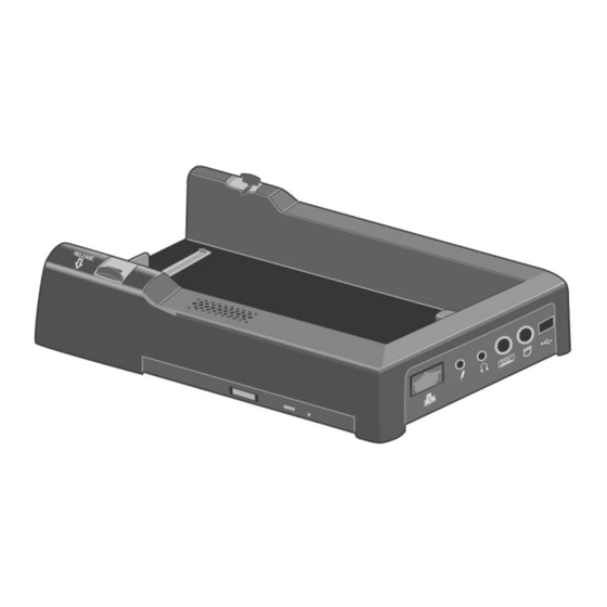
2 Names and Functions of Parts The port replicator allows your peripheral devices to function exactly as if they were con- The port replicator allows your peripheral devices to function exactly as if they were con- nected directly to the computer. nected directly to the computer. -
Page 7: Connecting/Disconnecting
If the computer malfunctions while connected to the port replicator, power off the computer, disconnect the port replicator, connect the AC adaptor to the computer, and check to see if the computer operates normally. If the computer operates normally, the port replicator may be malfunctioning. Contact Panasonic Technical Support. - Page 8 Connect the port replicator to a power outlet. To the wireless AC Cord* display DC type cover and cable* AC Adaptor* Included with the wireless display. Included with the computer. CAUTION Use only the specified AC adaptor (Model No. CF-AA1639A) and AC cord. Refer to the Operating Instructions included with the computer for informa- tion on the proper handling of the AC adaptor and AC cord.
- Page 9 Connecting/Disconnecting Disconnecting Shut down the computer. CAUTION Do not shut down using the standby or hiberna- tion mode. Levers Slide the levers in the directions indicated by the ar- rows at the same time. The computer's connector will disengage the expansion bus connector of the port replicator.
-
Page 10: Wiring Connection Diagram⋅ ⋅ ⋅ ⋅ ⋅ ⋅ ⋅ ⋅ ⋅ ⋅ ⋅ ⋅ ⋅ ⋅ ⋅ ⋅ ⋅ ⋅ ⋅ ⋅ ⋅ ⋅ ⋅ ⋅ ⋅ ⋅ ⋅ ⋅ ⋅ ⋅ ⋅ ⋅ ⋅ ⋅ ⋅ ⋅ ⋅ ⋅ ⋅ ⋅ ⋅ ⋅ ⋅ ⋅ ⋅ ⋅ ⋅ ⋅ ⋅ ⋅ ⋅ ⋅ ⋅ ⋅ ⋅ ⋅ ⋅ ⋅ ⋅ ⋅ ⋅ ⋅ ⋅ ⋅ ⋅ ⋅ ⋅ ⋅7
4 Wiring Connection Diagram... -
Page 11: Disassembly/Reassembly
5 Disassembly/Reassembly <A torque for tightening screws> 1.1. Removing the left and right Rock Please refer to the torque described on Exploded View. Blocks Removing the Top Cabinet 1. Remove the left and right retaining sheets. 2. Remove the 4 screws and release the left and right rock 1. - Page 12 Removing the Main Board 3.1. Removing the left and right CDD Angle Brackets 1. Disconnect the 4 flexible cables. 1. Remove the 4 screws and release the CDD left & right 2. Remove the single screw <C> at the back. angle brackets.
- Page 13 Removing the DU Connector < Preparation for Speaker> 1. Remove the 3 screws and release the EXT bus angle bracket block. 1. Soldering the speaker cable as shown below. 2. Disconnect the DC IN connector. Screw <A>:XYN26+J5FN 3. Remove the 2 screws and release the I/O dock leg. 4.
-
Page 14: Exploded View ⋅ ⋅ ⋅ ⋅ ⋅ ⋅ ⋅ ⋅ ⋅ ⋅ ⋅ ⋅ ⋅ ⋅ ⋅ ⋅ ⋅ ⋅ ⋅ ⋅ ⋅ ⋅ ⋅ ⋅ ⋅ ⋅ ⋅ ⋅ ⋅ ⋅ ⋅ ⋅ ⋅ ⋅ ⋅ ⋅ ⋅ ⋅ ⋅ ⋅ ⋅ ⋅ ⋅ ⋅ ⋅ ⋅ ⋅ ⋅ ⋅ ⋅ ⋅ ⋅ ⋅ ⋅ ⋅ ⋅ ⋅ ⋅ ⋅ ⋅ ⋅ ⋅ ⋅ ⋅ ⋅ ⋅ ⋅ ⋅ ⋅ ⋅ ⋅ ⋅ ⋅ ⋅ ⋅ ⋅ ⋅ ⋅ ⋅9
6 Exploded View... -
Page 15: Replacement Parts List Comparison Table ⋅ ⋅ ⋅ ⋅ ⋅ ⋅ ⋅ ⋅ ⋅ ⋅ ⋅ ⋅ ⋅ ⋅ ⋅ ⋅ ⋅ ⋅ ⋅ ⋅ ⋅ ⋅ ⋅ ⋅ ⋅ ⋅ ⋅ ⋅ ⋅ ⋅ ⋅ ⋅ ⋅ ⋅ ⋅ ⋅ ⋅ ⋅ ⋅ ⋅ ⋅ ⋅ ⋅ ⋅ ⋅ ⋅10-1
7 Replacement Parts List Comparison Table Note: Important Safety Notice Components identified by mark have special characteristics important for safety. When replacing any of these components, use only manufacturer's specified parts. CF-VEB071W REF. NO and AREA PART NO. DESCRIPTION Q'TY Main Block Unit DFAS40D03ZAF SPEAKER... - Page 16 DFMD7807ZB ANGLE, LOCK DFMD7812ZB ANGLE DFMD9072ZB ASS'Y, ANGLE, EXT BUS DFME0128ZA SHAFT DFME0129ZA PUSH NUT DFMX0955ZA SHEET, CDD DFMX0960ZA SHEET, FFC DFQT6232ZA LABEL, SETUP CAUTION DFUA9079ZB-0 ASS'Y, IO PLATE DFUE0023ZA SPRING, LOCK DFUS0286ZA SPRING, EMI DFMD7851ZA ANGLE, IO DOCK DFMC0685ZA CONDUCTIVE SHEET DFHE0219ZA GASKET B...
- Page 17 IC10 DA7787FSE2E IC, BI-POLAR LINEAR C47 82 84 DCSG1AB470RR CAPACITOR, 10V, 47µF L16 17 18 DEAM51R0P506 FERRITE BEAD DECU25000L3U OSCILLATOR, 25MHz DEDRB715FT7 DIODE C14 36 ECST0JZ106R CAPACITOR, 6.3V, 10µF ECST1AX226R CAPACITOR, 10V, 22µF C26 85 EEJK1AS106R CAPACITOR, 10V, 10µF ERJ12YJ3R3H RESISTOR, 1/2W, 3.3Ω...
- Page 18 L4 5 6 7 NFM61R00T361 INDUCTOR LA3 4 ACM45321023P FERRITE BEAD ARRAY, FILTER PS3 4 DBTMNSMD075 POLY SWITCH ECST0JZ106R CAPACITOR, 6.3V, 10µF C5 6 ECST0JZ475R CAPACITOR, 6.3V, 4.7µF ERJ3GEYJ104V RESISTOR, 1/16W, 100KΩ ERY32SA120VA POLY SWITCH, 1.2A EXBV8V750JV RESISTOR ARRAY CA1 2 3 4 5 EZASCE101M CAPACITOR ARRAY C16 19...
Need help?
Do you have a question about the CF-VEB071 and is the answer not in the manual?
Questions and answers