Table of Contents
Advertisement
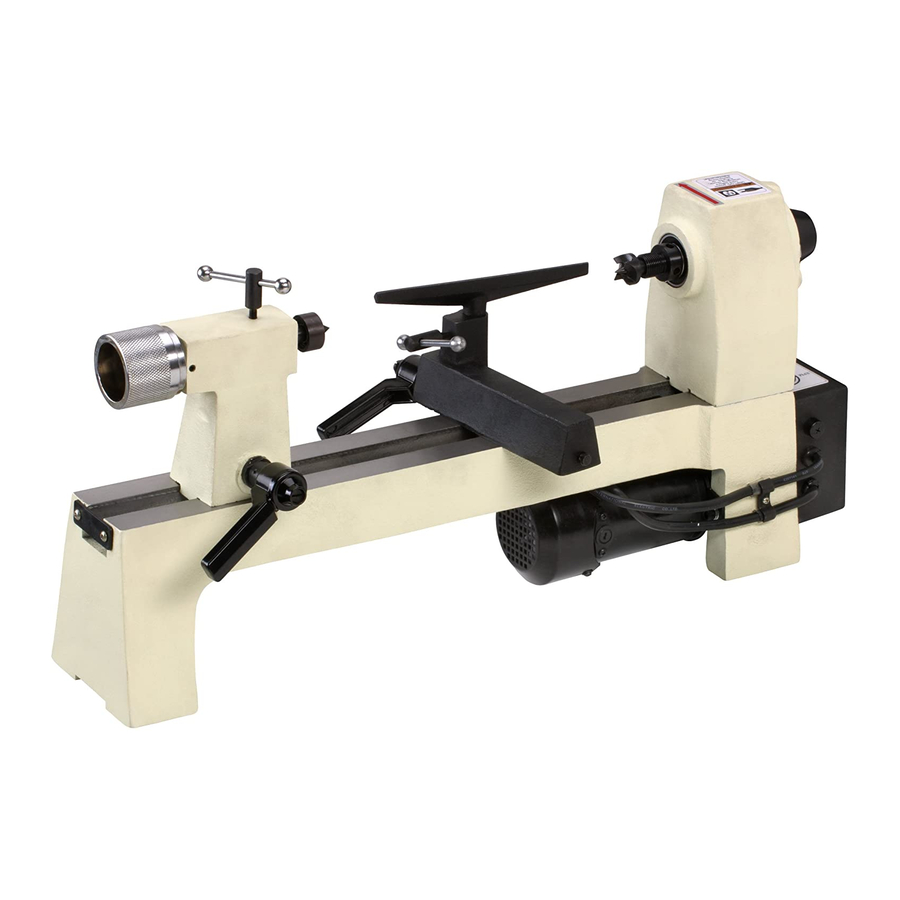
MODEL W1704
8" X 13" BENCHTOP
WOOD LATHE
OWNER'S MANUAL
(FOR MODELS MANUFACTURED SINCE 01/20)
Phone: (360) 734-3482 • Online Technical Support: techsupport@woodstockint.com
COPYRIGHT © DECEMBER, 2003 BY WOODSTOCK INTERNATIONAL, INC. REVISED JANUARY, 2020 (MN)
WARNING: NO PORTION OF THIS MANUAL MAY BE REPRODUCED IN ANY SHAPE OR FORM WITHOUT
THE WRITTEN APPROVAL OF WOODSTOCK INTERNATIONAL, INC.
#5378TR Printed in China
4000909
Advertisement
Table of Contents

Related Manuals for Woodstock Shop Fox W1704


Summary of Contents for Woodstock Shop Fox W1704
- Page 1 MODEL W1704 8" X 13" BENCHTOP WOOD LATHE OWNER'S MANUAL (FOR MODELS MANUFACTURED SINCE 01/20) Phone: (360) 734-3482 • Online Technical Support: techsupport@woodstockint.com COPYRIGHT © DECEMBER, 2003 BY WOODSTOCK INTERNATIONAL, INC. REVISED JANUARY, 2020 (MN) WARNING: NO PORTION OF THIS MANUAL MAY BE REPRODUCED IN ANY SHAPE OR FORM WITHOUT THE WRITTEN APPROVAL OF WOODSTOCK INTERNATIONAL, INC. #5378TR Printed in China 4000909...
- Page 2 This manual provides critical safety instructions on the proper setup, operation, maintenance, and service of this machine/tool. Save this document, refer to it often, and use it to instruct other operators. Failure to read, understand and follow the instructions in this manual may result in fire or serious personal injury—including amputation, electrocution, or death.
-
Page 3: Table Of Contents
Contents INTRODUCTION........2 ACCESSORIES........32 Woodstock Technical Support ....2 Wood Lathe Accessories ....... 32 Machine Specifications ......3 MAINTENANCE........34 Identification ........5 General .......... 34 Controls & Components ......6 Cleaning & Protecting ......34 SAFETY..........7 Lubrication ........34 Standard Machinery Safety Instructions .. -
Page 4: Introduction
Woodstock International, Inc. is committed to customer satisfaction. Our intent with this manual is to include the basic information for safety, setup, operation, maintenance, and service of this product. -
Page 5: Machine Specifications
Model W1704 (For Machines Mfd. Since 01/20) MODEL W1704 8" X 13" BENCHTOP WOOD LATHE Product Dimensions Weight......................41 lbs. Width (side‐to‐side) x Depth (front‐to‐back) x Height........29 x 10‐1/2 x 13 in. Footprint (Length x Width)..............23‐1/2 x 5‐1/2 in. Shipping Dimensions Type.................... - Page 6 Model W1704 (For Machines Mfd. Since 01/20) Spindle Information Spindle Taper....................MT#1 Spindle Thread Size................3/4" x 16 TPI Spindle Thread Direction................. Right Hand Spindle Bore................... 0.394 in. Type of Included Spindle Center................ Spur Tailstock Information Tailstock Taper................... MT#1 Type of Included Tailstock Center..............Live Construction Bed................
-
Page 7: Identification
Model W1704 (For Machines Mfd. Since 01/20) Identification Become familiar with the names and locations of the controls and features shown below to better understand the instructions in this manual. Spindle Headstock Spindle Tool Rest Quill Tailstock Speed Dial Base Lock Handle Adjustment Knob Quill... -
Page 8: Controls & Components
Model W1704 (For Machines Mfd. Since 01/20) Controls.&.Components Refer to Figures.1–3 and the following descriptions to become familiar with the basic controls and components of this machine. Understanding these items and how they work will help you understand the rest of the manual and stay safe when operating this machine. -
Page 9: Safety
Model W1704 (For Machines Mfd. Since 01/20) SAFETY SAFETY For.Your.Own.Safety, Read.Manual.Before.Operating.Machine The. purpose. of. safety. symbols. is. to. attract. your. attention. to. possible. hazardous. conditions.. This. manual.uses.a.series.of.symbols.and.signal.words.intended.to.convey.the.level.of.importance.of.the. safety.messages..The.progression.of.symbols.is.described.below..Remember.that.safety.messages.by. themselves. do. not. eliminate. danger. and. are. not. a. substitute. for. proper. accident. prevention. mea- sures—this.responsibility.is.ultimately.up.to.the.operator! Indicates.an.imminently.hazardous.situation.which,.if.not.avoided,. - Page 10 INTENDED.USAGE..Only use machine for its keep machine in good working condition. A intended purpose—never make modifications machine that is improperly maintained could without prior approval from Woodstock malfunction, leading to serious personal injury International. Modifying machine or using or death.
-
Page 11: Additional Safety For Wood Lathes
Model W1704 (For Machines Mfd. Since 01/20) Additional.Safety.for.Wood.Lathes MAIN.INJURY.HAZARDS:.Death.or.crushing.injury.from.getting.entangled.in.rotating.spindle.or. workpiece;.death,.blindness,.or.broken.bones.from.being.struck.by.a.workpiece.that.breaks. apart.or.comes.loose.during.rotation,.turning.tool.kickback,.or.flying.wood.chips..To.minimize. your.risk.of.these.hazards,.always.heed.the.following.warning.information: INTEGRITY.OF.STOCK. Verify each workpiece is EYE/FACE.PROTECTION. Always wear a face free of knots, splits, nails, or foreign material shield and safety glasses when operating lathe. to ensure it can safely rotate on spindle without breaking apart or causing turning tool PROPER.APPAREL. -
Page 12: Glossary Of Terms
Model W1704 (For Machines Mfd. Since 01/20) Glossary.of.Terms The following is a list of common definitions, terms and phrases used throughout this manual as they relate to this wood lathe and woodworking in general. Become familiar with these terms for assembling, adjust- ing or operating this machine. -
Page 13: Electrical
Model W1704 (For Machines Mfd. Since 01/20) ELECTRICAL Circuit.Requirements This machine must be connected to the correct size and type of power supply circuit, or fire or electrical damage may occur. Read through this section to determine if an The machine must be properly set up adequate power supply circuit is available. -
Page 14: Grounding Requirements
Model W1704 (For Machines Mfd. Since 01/20) Grounding.Requirements This machine MUST be grounded. In the event of certain GROUNDED types of malfunctions or breakdowns, grounding provides 120V 5-15 RECEPTACLE a path of least resistance for electric current to travel—in order to reduce the risk of electric shock. Grounding Pin Improper connection of the equipment-grounding wire will increase the risk of electric shock. -
Page 15: Setup
Model W1704 (For Machines Mfd. Since 01/20) SETUP Unpacking This machine has been carefully packaged for safe This machine presents transportation. If you notice the machine has been serious injury hazards damaged during shipping, please contact your authorized to untrained users. Read Shop Fox dealer immediately. -
Page 16: Inventory
Model W1704 (For Machines Mfd. Since 01/20) Inventory The following is a list of items shipped with your machine. Before beginning setup, lay these items out and inventory them. Note: If you cannot find an item on this list, carefully check around/inside the machine and packaging materials. -
Page 17: Hardware Recognition Chart
Model W1704 (For Machines Mfd. Since 01/20) Hardware.Recognition.Chart USE THIS CHART TO IDENTIFY HARDWARE DURING THE INVENTORY/ASSEMBLY ⁄ " ⁄ " ⁄ " PROCESS. ⁄ " ⁄ " ⁄ " ⁄ " ⁄ " ⁄ " ⁄ " ⁄ " 10mm 12mm ⁄... -
Page 18: Cleaning Machine
Model W1704 (For Machines Mfd. Since 01/20) Cleaning.Machine Machine.Placement The unpainted surfaces of your machine are Workbench.Load coated with a heavy-duty rust preventative that Refer to the Machine.Specifications for the prevents corrosion during shipment and storage. weight and footprint specifications of your This rust preventative works extremely well, but machine. -
Page 19: Assembly
Model W1704 (For Machines Mfd. Since 01/20) lock levers Assembly Before beginning the assembly process, refer to Items. Needed.for.Setup and gather everything you need. Ensure all parts have been properly cleaned of any heavy-duty rust-preventative applied at the factory (if applicable). -
Page 20: Test Run
Model W1704 (For Machines Mfd. Since 01/20) Test.Run Once assembly is complete, test run the machine to ensure it is properly connected to power and safety components are functioning properly. Serious. injury. or. death. can. result. from. using. this. machine. BEFORE. If you find an unusual problem during the test run, understanding. -
Page 21: Operations
Model W1704 (For Machines Mfd. Since 01/20) OPERATIONS General This machine will perform many types of operations that are beyond the scope of this manual. Many of these operations can be dangerous or deadly if performed incorrectly. The instructions in this section are written with the understanding that the operator has the necessary knowledge and skills to operate this machine. -
Page 22: Workpiece Inspection
Model W1704 (For Machines Mfd. Since 01/20) Workpiece.Inspection Some workpieces are not safe to turn or may •. Large/Loose Knots:.Loose knots can require modification before they can be made become dislodged during the turning safe to turn. operation. Large knots can cause a workpiece to completely break in half Before.turning,.get.in.the.habit.of.inspecting. -
Page 23: Selecting Turning Tools
Model W1704 (For Machines Mfd. Since 01/20) Selecting.Turning.Tools Lathe tools come in a variety of shapes and sizes, and usually fall into five major categories. Gouges—Mainly used for rough cutting, detail • cutting, and cove profiles. The rough gouge is a hollow, double-ground tool with a round nose, and the detail gouge is a hollow, double-ground tool with either a round or pointed nose. -
Page 24: Adjusting Tailstock
Model W1704 (For Machines Mfd. Since 01/20) Adjusting.Tailstock The tailstock on this lathe is equipped with a cam-action clamping system to secure it to the lathe bed. When the lever is tightened, a locking plate lifts up underneath the bed and secures the tailstock in place. The tailstock can be positioned anywhere along the lathe bed. -
Page 25: Adjusting Tool Rest
Model W1704 (For Machines Mfd. Since 01/20) tool rest height Adjusting.Tool.Rest The tool rest assembly consists of two components: the tool rest base (or banjo) and the tool rest. The tool rest base moves forward/backward and along the length of the Improperly. -
Page 26: Installing/Removing Headstock Center
Model W1704 (For Machines Mfd. Since 01/20) Installing/Removing. Headstock.Center The included spur center installs in the headstock spindle with an MT#1 tapered fit. Center Items.Needed. Heavy Gloves/Clean Rag ........1 Knockout Rod ............1 Installing.Headstock.Center 1.. DISCONNECT MACHINE FROM POWER! Headstock 2. Make sure mating surfaces of center and spindle are Spindle free of debris and oily substances before inserting center to ensure a good fit and reduce runout. -
Page 27: Installing/Removing Tailstock Center
Model W1704 (For Machines Mfd. Since 01/20) Installing/Removing. Tailstock.Center The included live center installs into the tailstock quill Quill Adjustment Knob with an MT#1 tapered fit. Lock Handle Items.Needed. Heavy Gloves/Clean Rag ........1 Knockout Rod ............1 Installing.Tailstock.Center Center 1. Loosen quill lock handle, and rotate tailstock adjustment knob clockwise until quill extends about 1", as shown in Figure.22. -
Page 28: Installing/Removing Faceplate
Model W1704 (For Machines Mfd. Since 01/20) Headstock Faceplate Installing/Removing. Faceplate Faceplate These instructions cover removing and installing the faceplate. To mount a workpiece to your faceplate, refer to Faceplate.Turning on Page.30. Items.Needed. Knockout Open-End Wrench 19/27mm ........1 Knockout Rod ............1 Installing.Faceplate 1. -
Page 29: Changing Spindle Speed
Model W1704 (For Machines Mfd. Since 01/20) Changing Speed Ranges Changing.Spindle.Speed The Model W1704 utilizes a spindle speed dial (see Figure 26) that allows for on-the-fly spindle speed changes from 750 to 3200 RPM. Rotate the spindle speed dial clockwise Spindle to increase speed and counterclockwise to decrease Speed Dial... -
Page 30: Spindle Turning
Model W1704 (For Machines Mfd. Since 01/20) Spindle.Turning Spindle turning is the operation performed when a workpiece is mounted between the headstock and the tailstock, as shown in Figure 27. Bowls, table legs, tool handles, and candlesticks are typical projects where this operation is used. - Page 31 Model W1704 (For Machines Mfd. Since 01/20) 6. Drive spur center into end center mark of workpiece with a wood mallet to embed it at least ⁄ " into workpiece, as shown in Figure.30. 7. With workpiece still attached, insert spur center into headstock spindle (refer to Installing/Removing.
-
Page 32: Faceplate Turning
Faceplate Turning Model W1704 (For Machines Mfd. Since 01/20) Faceplate.Turning Faceplate turning is when a workpiece is mounted to the faceplate, which is then mounted to the headstock spindle, as shown in Figure.31. This type of turning is usually done with open-faced workpieces like bowls or plates. -
Page 33: Sanding/Finishing
Model W1704 (For Machines Mfd. Since 01/20) Sanding/Finishing After the turning operations are complete, the workpiece can be sanded and finished before removing it from the lathe, as shown in Figure.34. Note: Whenever sanding or finishing, move the tool rest holder out of the way to increase personal safety and gain adequate working room. -
Page 34: Accessories
Dealer. If you do not have a dealer in your area, these products are also available through online deal- ers. Please call or e-mail Woodstock International Inc. Customer Service to get a current listing of deal- ers at: 1-800-545-8420 or at sales@woodstockint.com. - Page 35 Model W1704 (For Machines Mfd. Since 01/20) The.D4058.3-Pc..HSS.Lathe.Chisel.Set.is ideal for bowl turning and detail work. Each chisel measures roughly 16" long, with 10" ash han- dles, and the high-speed steel blades measure a full ⁄ " thick! The set includes one round, one curved, and one 90° corner chisel. Chisel set is protected in a fitted wooden box.
-
Page 36: Maintenance
Model W1704 (For Machines Mfd. Since 01/20) MAINTENANCE General For optimum performance from your machine, follow this maintenance schedule and refer to any specific instructions given in this section. Ongoing • Loose faceplate or mounting bolts. • Damaged center or tooling. •... -
Page 37: Service
If you require additional machine service not included in this section, please contact Woodstock International Technical Support at (360) 734-3482 or send e-mail to: techsupport@woodstockint.com. MAKE. SURE. that. your. machine. is. -
Page 38: Changing/Tensioning Belt
Model W1704 (For Machines Mfd. Since 01/20) Changing/Tensioning.Belt Over time, the belt will slightly wear and stretch, eventu- ally losing its efficiency of transmitting power, and will require re-tensioning. A new belt typically has a break-in period and should be checked/re-tensioned after the first 16 hours of belt life, as it will stretch during this time. -
Page 39: Replacing Fuse
Model W1704 (For Machines Mfd. Since 01/20) Replacing.Fuse This machine features an onboard fuse designed to protect sensitive electrical parts in the event of electrical overload. If the fuse has blown, the motor will not start. To verify the condition of the fuse, remove it from the switch box and hold it up to the light. -
Page 40: Troubleshooting
Model W1704 (For Machines Mfd. Since 01/20) Troubleshooting The following troubleshooting tables cover common problems that may occur with this machine. If you need replacement parts or additional troubleshooting help, contact our Technical Support. Note: Before contacting Tech Support, find the machine serial number and manufacture date, and if available, your original purchase receipt. - Page 41 Model W1704 (For Machines Mfd. Since 01/20) Operation PROBLEM POSSIBLE.CAUSE CORRECTIVE.ACTION Bad surface 1. Dull tooling or wrong tool used for task. 1. Sharpen tooling, select correct tool for operation. finish. 2. Tool height is not ⁄ " above spindle center- 2.
-
Page 42: Electrical Safety Instructions
Model W1704 (For Machines Mfd. Since 01/20) Electrical.Safety.Instructions These pages are current at the time of printing. However, in the spirit of improvement, we may make changes to the electrical systems of future machines. Compare the manufacture date of your machine to the one stated in this manual, and study this section carefully. -
Page 43: Electrical Components
Model W1704 (For Machines Mfd. Since 01/20) Electrical.Components Spindle Speed Dial Fuse Holder ON/OFF Switch Motor Cord Power Circuit Cord Board Figure.41. Switch box wiring and components. -41-... -
Page 44: Wiring Diagram
Model W1704 (For Machines Mfd. Since 01/20) Wiring.Diagram PADDLE SWITCH Read Page 40 STOP Before Wiring Green Ground White Neutral 5-15 Plug Black FUSE 10A CIRCUIT BOARD Ground MOTOR SHOCK HAZARD! The motor wiring shown here is Disconnect power current at the time of printing, but before working on it may not match your machine. -
Page 45: Parts
Model W1704 (For Machines Mfd. Since 01/20) PARTS Main 9 10 30V2 64 65 42V2 36V2 41V2-1 41V2 61 62 41V2-2 68-1 -43-... - Page 46 Model W1704 (For Machines Mfd. Since 01/20) Main.Parts.List REF PART # DESCRIPTION PART # DESCRIPTION X1704001 41V2 X1704041V2 MOTOR V2.01.20 X1704002 RETAINING PLATE 41V2-1 X1704041V2-1 CARBON BRUSH X1704003 PHLP HD SCR M5-.8 X 8 41V2-2 X1704041V2-2 BRUSH CAP X1704004 SET SCREW M6-1 X 8 DOG-PT 42V2 X1704042V2 MACHINE ID LABEL V2.01.20...
-
Page 47: Warranty
Woodstock International, Inc. will repair, replace, or arrange for a dealer refund, at its expense and option, the Shop Fox machine or machine part proven to be defective for its designed and intended...
Need help?
Do you have a question about the Shop Fox W1704 and is the answer not in the manual?
Questions and answers