Table of Contents
Advertisement
Quick Links
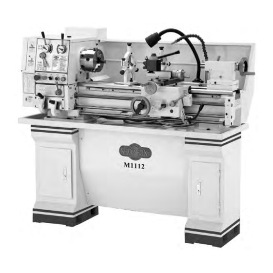
MODEL M1112 12" X 36"
GUNSMITHING LATHE
OWNER'S MANUAL
(FOR MODELS MANUFACTURED SINCE 12/20)
Phone: (360) 734-3482 • Online Technical Support: techsupport@woodstockint.com
COPYRIGHT © NOVEMBER 2007 BY WOODSTOCK INTERNATIONAL, INC., REVISED DECEMBER, 2020 (BL)
WARNING: NO PORTION OF THIS MANUAL MAY BE REPRODUCED IN ANY SHAPE OR FORM WITHOUT
THE WRITTEN APPROVAL OF WOODSTOCK INTERNATIONAL, INC.
Printed in China
#10091CR
Advertisement
Table of Contents

Related Manuals for Woodstock Shop Fox M1112


Summary of Contents for Woodstock Shop Fox M1112
- Page 1 (FOR MODELS MANUFACTURED SINCE 12/20) Phone: (360) 734-3482 • Online Technical Support: techsupport@woodstockint.com COPYRIGHT © NOVEMBER 2007 BY WOODSTOCK INTERNATIONAL, INC., REVISED DECEMBER, 2020 (BL) WARNING: NO PORTION OF THIS MANUAL MAY BE REPRODUCED IN ANY SHAPE OR FORM WITHOUT THE WRITTEN APPROVAL OF WOODSTOCK INTERNATIONAL, INC.
- Page 2 This manual provides critical safety instructions on the proper setup, operation, maintenance, and service of this machine/tool. Save this document, refer to it often, and use it to instruct other operators. Failure to read, understand and follow the instructions in this manual may result in fire or serious personal injury—including amputation, electrocution, or death.
-
Page 3: Table Of Contents
Table of Contents INTRODUCTION ........2 MAINTENANCE ........39 Woodstock Technical Support ....2 General Maintenance ......39 Controls and Features ......6 General Cleaning ....... 39 General Lubrication ......39 SAFETY ..........7 Coolant System ......... 41 Standard Machinery Safety Instructions ..7 SERVICE .......... -
Page 4: Introduction
Woodstock International, Inc. is committed to customer satisfaction. Our intent with this manual is to include the basic information for safety, setup, operation, maintenance, and service of this product. - Page 5 Model M1112 (For Machines Mfd. Since 12/20) MODEL M1112 GUNSMITH LATHE WITH STAND Product Dimensions Weight......................1213 lbs. Width (side‐to‐side) x Depth (front‐to‐back) x Height........61 x 26 x 54‐1/2 in. Footprint (Length x Width)..............57‐1/2 x 14‐1/2 in. Shipping Dimensions Carton #1 Type....................
- Page 6 Model M1112 (For Machines Mfd. Since 12/20) Main Specifications Operation Info Swing Over Bed................... 12 in. Distance Between Centers................36 in. Swing Over Cross Slide..................7 in. Swing Over Saddle................11‐11/32 in. Maximum Tool Bit Size................. 5/8 in. Compound Travel..................3‐1/4 in. Carriage Travel...................
- Page 7 Model M1112 (For Machines Mfd. Since 12/20) Fluid Capacities Headstock Capacity..................3.5 qt. Headstock Fluid Type........ISO 32 (eg. Grizzly T23963, Mobil DTE Light) Gearbox Capacity................. 1 – 2 Pumps Gearbox Fluid Type......... ISO 68 (eg. Grizzly T23962, Mobil Vactra 2) Apron Capacity..................
-
Page 8: Controls And Features
Model M1112 (For Machines Mfd. Since 12/20) Controls and Features Model M1112 lathe. A. Quick Change Gearbox Levers Q. Compound Rest Handwheel B. Feed Rod Lever R. Tailstock Spindle and Center C. Emergency Stop/RESET Button Tailstock Spindle Lock Lever D. POWER START Button T. -
Page 9: Safety
Model M1112 (For Machines Mfd. Since 12/20) SAFETY SAFETY For Your Own Safety, Read Manual Before Operating Machine The purpose of safety symbols is to attract your attention to possible hazardous conditions. This manual uses a series of symbols and signal words intended to convey the level of importance of the safety messages. - Page 10 INTENDED USAGE. Only use machine for its keep machine in good working condition. A intended purpose—never make modifications machine that is improperly maintained could without prior approval from Woodstock malfunction, leading to serious personal injury International. Modifying machine or using or death.
-
Page 11: Additional Safety For Metal Lathes
Model M1112 (For Machines Mfd. Since 12/20) Additional Safety for Metal Lathes Serious injury or death can occur from getting entangled in, crushed between, or struck by rotating parts on a lathe! Unsecured tools or workpieces that fly loose from rotating objects can also strike nearby operators with deadly force. -
Page 12: Avoiding Potential Injuries
Model M1112 (For Machines Mfd. Since 12/20) Avoiding Potential Injuries Figure 3. Always wear face and eye protection Figure 1. Always protect the bed ways, and when using lathes. unplug the lathe when retooling the lathe. Figure 4. Never use hands to stop or slow the Figure 2. -
Page 13: Electrical
Model M1112 (For Machines Mfd. Since 12/20) ELECTRICAL Circuit Requirements This machine must be connected to the correct size and type of power supply circuit, or fire or electrical damage may occur. Read through this section to determine if an The machine must be properly set up adequate power supply circuit is available. -
Page 14: Grounding Requirements
Model M1112 (For Machines Mfd. Since 12/20) Grounding Requirements This machine MUST be grounded. In the event of certain types of malfunctions or breakdowns, grounding provides a path of least resistance for electric current to travel—in order to reduce the risk of electric shock. Improper connection of the equipment-grounding wire will increase the risk of electric shock. -
Page 15: Set Up
If any parts are missing, find the part num- ber in the back of this manual and contact Main Components (Figure 7) Woodstock International, Inc. at (360) 734- A. 6" Three-Jaw Chuck w/Jaws ......1 3482 or at tech-support@shopfox.biz B. Steady Rest ..........1 C. -
Page 16: Uncrating And Lifting
Model M1112 (For Machines Mfd. Since 12/20) Uncrating and Lifting The Model M1112 lathe has been carefully crated. If you notice the lathe has been damaged, contact your SHOP FOX authorized dealer immediately. ® To lift and move the lathe, do these steps: 1. -
Page 17: Cleaning Machine
Model M1112 (For Machines Mfd. Since 12/20) Cleaning Machine The ways and other unpainted parts of your lathe are coated with a waxy grease that protects them from corrosion during shipment. Clean this grease off with a ALWAYS work well- solvent cleaner or citrus-based degreaser. -
Page 18: Mounting To Shop Floor
Model M1112 (For Machines Mfd. Since 12/20) Mounting to Shop Floor NOTICE Anchor studs are stronger and more Although not required, we recommend that you mount permanent alternatives to lag shield your new machine to the floor. Because this is an optional anchors;... -
Page 19: Lubricating Lathe
Model M1112 (For Machines Mfd. Since 12/20) Lubricating Lathe The headstock, quick-change gearbox, and apron must be properly lubricated before the lathe can be operated. GEARBOXES MUST Damage caused to the bearings and gears from running the BE FILLED WITH OIL! lathe without proper lubrication will not be covered under warranty. - Page 20 Model M1112 (For Machines Mfd. Since 12/20) 5. Rotate the red stop/RESET button (Figure 15) Speed Levers clockwise so it pops out. 6. Make sure the spindle rotation ON/OFF lever is in the central or neutral position (Figure 14). 7. Move the speed levers to B and so the spindle will rotate at 70 RPM (Figure 15).
-
Page 21: Tailstock
Model M1112 (For Machines Mfd. Since 12/20) Tailstock The tailstock alignment was set at the factory with the headstock. However, we recommend that you take the time to ensure that the tailstock is aligned to your own desired tolerances. To align the tailstock, do these steps: 1. - Page 22 Model M1112 (For Machines Mfd. Since 12/20) 8. Loosen the tailstock lock lever and adjust the tailstock offset by half the taper by turning the Move tailstock toward front of lathe adjustment set screw (Figure 20). Turn another amount of taper. 0.010'' off of the stock and check for taper.
-
Page 23: Operations
Model M1112 (For Machines Mfd. Since 12/20) OPERATIONS General NOTICE Complete the Test Run and Break-In procedure on Page 17 before using this lathe for any cutting or threading operations; otherwise, gear box damage may occur. The Model M1112 will perform many types of operations Always wear safety goggles when oper- that are beyond the scope of this manual. -
Page 24: Mounting Chuck Or Faceplate
Model M1112 (For Machines Mfd. Since 12/20) Mounting Chuck or Faceplate The Model M1112 is shipped with the 3-jaw chuck installed. This is a scroll-type chuck, meaning that all three jaws move in unison when adjusted. The 4-jaw chuck, on the other hand, features independent jaws. - Page 25 Model M1112 (For Machines Mfd. Since 12/20) To install a chuck, do these steps: 1. DISCONNECT LATHE FROM POWER! Camlock Stud 2. Place a piece of plywood across the lathe bed, wipe clean the spindle nose taper (Figure 25) and the mating surface on the chuck with a rag.
- Page 26 Model M1112 (For Machines Mfd. Since 12/20) To load a workpiece, do these steps: 1. With the chuck key, open the jaws so the workpiece lays flat against the chuck face and jaw step or fits in the through hole. For jaw and work holding options, see Figure 27.
-
Page 27: Swapping Jaws
Model M1112 (For Machines Mfd. Since 12/20) Swapping Jaws The three-jaw scroll chuck has removable hardened steel jaws (Figure 28). The outside of the jaws are used to hold the workpiece from the outer diameter. Numbered from 1–3, the jaws must be used in the matching numbered jaw guides, see (Figure 29). -
Page 28: Four-Jaw Chuck
Model M1112 (For Machines Mfd. Since 12/20) Four-Jaw Chuck Four-jaw chucks feature hardened steel jaws that are adjusted independently. Each jaw can be removed from the chuck body and reversed. Independent jaw adjustment and re versal allows for a wide range of work holding versatility. -
Page 29: Faceplate
Model M1112 (For Machines Mfd. Since 12/20) 7. Make fine adjustments by slightly loosening one jaw and tightening the opposing jaw until the workpiece is precisely aligned. 8. Use a dial indicator to fine-tune your adjustments (see Figure 33), and use a lower RPM when machining heavy eccentric workpieces. -
Page 30: Centers
Model M1112 (For Machines Mfd. Since 12/20) Centers A tailstock center supports stock that is too long to be supported by the chuck alone. The tailstock barrel and live center have an MT#3 taper. Included with this lathe is an MT#3 to MT#5 spindle sleeve. If you need to install a center in the spindle when using the faceplate, you can do so by using this adapter sleeve. -
Page 31: Steady Rest
Model M1112 (For Machines Mfd. Since 12/20) Steady Rest The steady rest supports long, small diameter stock that otherwise could not be turned because of deflection. The steady rest fingers are fitted with bearings that maintain consistent non-wearing support throughout the cut. The steady rest can also be used in place of the tailstock to allow for cutting tool access at the end of your workpiece. -
Page 32: Feed Direction Lever
Model M1112 (For Machines Mfd. Since 12/20) Feed Direction Lever NOTICE NEVER attempt to shift a lever while the lathe is running! And when shifting a lever, NEVER force it. If the lever will not engage, rotate the chuck by hand while keeping light pressure on the lever. -
Page 33: Gearbox Levers
Model M1112 (For Machines Mfd. Since 12/20) Gearbox Levers NOTICE NEVER attempt to shift a lever while the lathe is running! And when shifting a lever, NEVER force it. If the lever will not engage, rotate the chuck by hand while keeping light pressure on the lever. -
Page 34: Carriage/Cross Feed Lever
Model M1112 (For Machines Mfd. Since 12/20) Carriage/Cross Feed Lever Longitudinal and cross slide powered motions are controlled by the carriage/cross feed lever. The lever pivots through two stops that require moving the lever left and right as well as up and down. Moving this lever upward activates the automatic longitudinal feed. -
Page 35: Change Gears & Metric Threading
Model M1112 (For Machines Mfd. Since 12/20) While other thread pitches may be achieved, the Model M1112 is designed so that gear changes are not needed for cutting inch threads. However, you will have to move the feed direction lever to the direction of thread you want to cut, and then move the feed rod lever to the right. - Page 36 Model M1112 (For Machines Mfd. Since 12/20) 4. In the “Combination of Gears” column (Figure 49) are 3 small columns. The numbers below F and G represent the number of gear teeth on a change gear. Find the required change gears that have the corresponding number of teeth as stated in the chart to the left of the desired pitch.
-
Page 37: Carriage Handwheels
Model M1112 (For Machines Mfd. Since 12/20) Carriage Handwheels Carriage Handwheel The carriage handwheel (Figure 50) moves the carriage Compound left or right along the bed. This manual control is Slide necessary when setting up the machine for turning Handwheel Cross Slide or when manual movement is desired during turning Handwheel... -
Page 38: Tailstock
Model M1112 (For Machines Mfd. Since 12/20) Tailstock The tailstock (Figure 52) serves many functions. The primary use is for holding centers and drill chucks. The Tailstock barrel has a Morse taper 3 bore and is imprinted with Handwheel graduations in millimeters and inches. Tailstock Handwheel Turning the handwheel advances or retracts the barrel in the tailstock. -
Page 39: Cutting Shallow Tapers With Tailstock
Model M1112 (For Machines Mfd. Since 12/20) Cutting Shallow Tapers with Tailstock The tailstock can be offset to cut a shallow taper on a shaft or barrel. Offset To set up the tailstock to cut tapers, do these steps: Adjustment 1. -
Page 40: Model M1112 Lathe Accessories
If you do not have a dealer in your area, these products are also available through online dealers. Please call or e-mail Woodstock International Inc. Customer Service to get a current listing of dealers at: (360) 734-3482 or at sales@woodstockint.com. -
Page 41: Maintenance
Model M1112 (For Machines Mfd. Since 12/20) MAINTENANCE General Maintenance Before every use, check for loose mounting bolts, chuck mounting, safety feature operation, worn or damaged electrical cords, and any other condition that could hamper the safe operation of this machine. General Cleaning Take the time to wipe down and oil your lathe after use. - Page 42 Model M1112 (For Machines Mfd. Since 12/20) Slides and Ways Wipe the ways with a clean rag and apply oil before Lead Screw and after each use. Apply oil to the bedways and other Feed Rod bare metal parts to also protect the lathe from rust and pitting.
-
Page 43: Coolant System
Model M1112 (For Machines Mfd. Since 12/20) Coolant System To maintain the coolant system, do these steps: 1. DISCONNECT THE LATHE FROM POWER! Drain 2. Remove the drain plug from the tank, drain the Pump Tube coolant out, and discard properly as hazardous waste. -
Page 44: Service
Model M1112 (For Machines Mfd. Since 12/20) SERVICE Troubleshooting The following troubleshooting tables cover common problems that may occur with this machine. If you need replacement parts or additional troubleshooting help, contact our Technical Support. Note: Before contacting Tech Support, find the machine serial number and manufacture date, and if available, your original purchase receipt. - Page 45 Model M1112 (For Machines Mfd. Since 12/20) Operation & Work Results Symptom Possible Cause Corrective Action Entire machine 1. Workpiece is unbalanced. 1. Reinstall workpiece so it is as centered with the vibrates exces- spindle bore as possible. sively upon start- 2.
-
Page 46: Gibs
Model M1112 (For Machines Mfd. Since 12/20) Gibs NOTICE When adjusting gibs, keep in mind that the goal of gib adjustment is to remove unnecessary sloppiness from the slide movement without causing them to bind. Loose gibs may cause poor finishes on the workpiece. -
Page 47: Half-Nut Adjustment
Model M1112 (For Machines Mfd. Since 12/20) Saddle Gib and Saddle Lock The saddle is supplied with a square head bolt (Figure Saddle Lock 62) on the front right hand side of the slide. This bolt Bolt locks the saddle in place for increased rigidity when making face cuts. -
Page 48: Adjusting/Replacing V-Belts
Model M1112 (For Machines Mfd. Since 12/20) Adjusting/Replacing V-Belts To replace or adjust the V-belts, do these steps: 1. DISCONNECT LATHE FROM POWER! 2. Open the change gear access door. 3. Loosen four motor mount bolts (Figure 64) and replace the belts as a matched set if required. 4. -
Page 49: Spindle Bearing Preload
Model M1112 (For Machines Mfd. Since 12/20) Spindle Bearing Preload This lathe is shipped from the factory with the spindle bearing preload adjusted. If the spindle ever develops a bit of end-play and the workpiece finish suffers, you can adjust the bearing preload to remove the end-play and improve the workpiece finish. - Page 50 Model M1112 (For Machines Mfd. Since 12/20) 7. Place a wooden block over the outboard end of the spindle, hit it soundly with a small sledge or heavy dead blow hammer. Your goal is to slide the spindle forward just enough to introduce spindle end-play that you can feel by hand.
- Page 51 Model M1112 (For Machines Mfd. Since 12/20) 12. Without causing the inner spanner nut to 3. Set the spindle speed to its highest setting. tighten any further, install and tighten the 4. Connect the lathe to power and turn the outer spanner nut against the inner nut.
-
Page 52: Electrical Safety Instructions
Model M1112 (For Machines Mfd. Since 12/20) Electrical Safety Instructions These pages are current at the time of printing. However, in the spirit of improvement, we may make changes to the electrical systems of future machines. Compare the manufacture date of your machine to the one stated in this manual, and study this section carefully. -
Page 53: M1112 Main Electrical Box Wiring Diagram
Model M1112 (For Machines Mfd. Since 12/20) M1112 Main Electrical WARNING Read Page 50 ACCIDENTAL INJURY STOP Box Wiring Diagram HAZARD! Disconnect power supply before Before adjustments, setup Wiring or maintenance! Main Electrical Box Relay Relay 20-21 = 110V JRS4-09/25d 110V JRS4-09/25d 20-22 = 220V... - Page 54 Model M1112 (For Machines Mfd. Since 12/20) Motor Thermal Pump Thermal Control System Overload Relay Overload Relay 2A, 110V Fuse System Transformer Pump Contactor KM1 Motor Direction A Contactor Work Lamp 5A 24V Fuse Motor KM2 Motor Inch/Jog Direction B Contactor Contactor Figure 71.
- Page 55 Model M1112 (For Machines Mfd. Since 12/20) Emergency Power Pump Inch/Jog Power Stop Button Button Switch Button Lamp Figure 72. Control panel wiring. CONTROL PANEL INCH/JOG POWER POWER EMERGENCY BUTTON LAMP STOP BUTTON PUMP BUTTON SWITCH Yl/Gn Lt/Bl Read To Main Page 50 STOP Ground...
- Page 56 Model M1112 (For Machines Mfd. Since 12/20) Figure 73. Spindle motor wiring. SPINDLE MOTOR Capacitor Ground To Main 20MFD 450VAC Electrical Yl/Gn Page 51 Start Capacitor 150MFD 265VAC Read Page 50 STOP Before Wiring -54-...
- Page 57 Model M1112 (For Machines Mfd. Since 12/20) Figure 74. Spindle ON/OFF switch. SPINDLE ON/OFF SWITCH To Main Electrical Page 51 Read Page 50 STOP Before Wiring -55-...
- Page 58 Model M1112 (For Machines Mfd. Since 12/20) Figure 75. Pump wiring. PUMP MOTOR Ground Read Page 50 STOP Before Wiring Yl/Gn Start Capacitor 2MFD 450VAC To Main Electrical Page 51 -56-...
- Page 59 Model M1112 (For Machines Mfd. Since 12/20) WORK LAMP Figure 76. Work lamp wiring. To Main Electrical Page 51 PLUG WIRING Ground (Plug not included) Read Yl/Gn Page 50 To Main STOP Electrical Before Wiring Page 51 6-15 Plug (As recommended) -57-...
-
Page 60: Headstock Shifters & Change Gears
Model M1112 (For Machines Mfd. Since 12/20) Headstock Shifters & Change Gears -58-... - Page 61 Model M1112 (For Machines Mfd. Since 12/20) Headstock Shifters & Change Gear Parts PART # DESCRIPTION PART # DESCRIPTION 1000 XM11121000 CAP SCREW M12-1.75 X 30 1049 XM11121049 BUSHING 1001 XM11121001 PHLP HD SCR M3-.5 X 6 1050 XM11121050 SHIFTING ARM 1002 XM11121002 FRONT CONTROL PLATE 1051...
-
Page 62: Headstock Gearing & Control Panel
Model M1112 (For Machines Mfd. Since 12/20) Headstock Gearing & Control Panel -60-... - Page 63 Model M1112 (For Machines Mfd. Since 12/20) Headstock Gearing & Control Panel Parts PART # DESCRIPTION PART # DESCRIPTION 1101 XM11121101 EXT RETAINING RING 45MM 1141 XM11121141 CAP SCREW M3-.5 X 8 1102 XM11121102 GEAR 36T 1142 XM11121142 SPINDLE 1103 XM11121103 GEAR 55T 1143 XM11121143 KEY 8 X 8 X 210...
-
Page 64: Quick Change Gearbox
Model M1112 (For Machines Mfd. Since 12/20) Quick Change Gearbox 2320 2301 2316 2318 2304 2302 2306 2315 2397 2314 2304 2308 2313 2310 2312 2322 2304 2309 2311 2351 2325 2305 2350 2306 2310 2349 2324 2327-1 2326 (2327) 2333 2348 2374... - Page 65 Model M1112 (For Machines Mfd. Since 12/20) Quick Change Gearbox Parts PART # DESCRIPTION PART # DESCRIPTION 2301 XM11122301 LEAD SCREW 2341 XM11122341 GEAR 16T 2302 XM11122302 ROLL PIN 5 X 36 2342 XM11122342 GEAR 32T 2304 XM11122304 THRUST BEARING 8103 2344 XM11122344 GEAR 16T 2305...
-
Page 66: Apron Assembly
Model M1112 (For Machines Mfd. Since 12/20) Apron Assembly -64-... - Page 67 Model M1112 (For Machines Mfd. Since 12/20) Apron Assembly Parts PART # DESCRIPTION PART # DESCRIPTION 2401V2 XM11122401V2 HANDLE V2.04.12 2436 XM11122436 SHAFT 2402V2 XM11122402V2 HANDWHEEL V2.04.12 2437 XM11122437 SAFETY SHIFTER 2403V2 XM11122403V2 GRADUATED DIAL V2.04.07 2438 XM11122438 SET SCREW M8-1.25 X 6 2404V2 XM11122404V2 SET SCREW M6-1 X 8 2439 XM11122439 COMPRESSION SPRING...
-
Page 68: Saddle & Cross Feed
Model M1112 (For Machines Mfd. Since 12/20) Saddle & Cross Feed 2514 2511 2512 2511 2513 2515 2509 2506 2508 2507 2505 2510 2503 2504 2502 2526 2501 2518 2522 2521 2520 2519 2523 2521 2541 2524 2534 2525 2533 2536 2540 2535... - Page 69 Model M1112 (For Machines Mfd. Since 12/20) Saddle & Cross Feed Parts PART # DESCRIPTION PART # DESCRIPTION 2501 XM11122501 SADDLE 2523 XM11122523 SLIDE PLATE 2502 XM11122502 PHLP HD SCR M3-.5 X 14 2524 XM11122524 SLIDE PLATE 2503 XM11122503 WIPER 2525 XM11122525 HEX BOLT M8-1.25 X 24 2504...
-
Page 70: Compound Rest
Model M1112 (For Machines Mfd. Since 12/20) Compound Rest 2640 2641 2603 2601 2602 2604 2606 2605 2607 2609 2612 2608 2621 2620 2617 2610 2611 2618 2613 2615 2619 2614 2642 2616 PART # DESCRIPTION PART # DESCRIPTION 2601 XM11122601 GIB SCREW 2613 XM11122613 THRUST BEARING 8101... -
Page 71: Tailstock Assembly
Model M1112 (For Machines Mfd. Since 12/20) Tailstock Assembly 3715 3713 3719 3711 3720 3710 3732 3721 3708 3714 3716 3704 3712 3722 3709 3717 3707 3733 3718 3728 3727 3724 3703 3706 3725 3731 3723V2 3702 3729 3705 PART # DESCRIPTION PART # DESCRIPTION... -
Page 72: Bed And Motor Parts
Model M1112 (For Machines Mfd. Since 12/20) Bed and Motor Parts -70-... -
Page 73: Cabinet Parts
Model M1112 (For Machines Mfd. Since 12/20) Cabinet Parts -71-... - Page 74 Model M1112 (For Machines Mfd. Since 12/20) Bed, Motor & Cabinet Parts PART # DESCRIPTION PART # DESCRIPTION 3801 XM11123801 V-BELT A-32 4L320 3813 XM11123813 CAP SCREW M6-1 X 25 3802 XM11123802 SET SCREW M5-.8 X 10 3818 XM11123818 PHLP HD SCR M6-1 X 10 3803 XM11123803 HEAD KEY...
-
Page 75: Spindle Switch Control Rod Assembly
Model M1112 (For Machines Mfd. Since 12/20) Spindle Switch Control Rod Assembly 4901 4902 4905 4903 4907V2 4902 4908 4906 4909 4904 4912 4910 4915 4917 4913 4911 4914 4921 4916 4922 4920 4918V2 4919V2 4924 4923 PART # DESCRIPTION PART # DESCRIPTION 4901... -
Page 76: Coolant System & Lamp
Model M1112 (For Machines Mfd. Since 12/20) Coolant System & Lamp REF PART # DESCRIPTION PART # DESCRIPTION 5501 XM11125501 COOLANT TANK 5508 XM11125508 PHLP HD SCR M6-1 X 16 5502 XM11125502 COOLANT PUMP ASSEMBLY 5511V2 XM11125511V2 LENS V2.01.15 5503 XM11125503 HEX BOLT M5-.8 X 25 5512V2 XM11125512V2... -
Page 77: Lathe Accessories
Model M1112 (For Machines Mfd. Since 12/20) Lathe Accessories 6402 6401 6404 6403 6401-1 6441 6435 6439 6434 6432 6406 6433 6431 6407 6405 6430 6442 6429 6421 6409 6423 6428 6410 6412 6411 6424 6414 6436-2 6425 6415 6426 6427 6422 6413... -
Page 78: Main Electrical Box
Model M1112 (For Machines Mfd. Since 12/20) Main Electrical Box 6503 6502 6501 6504 6510 6505 6506 6511 6507 6512 6508 6509 PART # DESCRIPTION PART # DESCRIPTION 6501 XM11126501 TRANSFORMER 6507 XM11126507 GROUND TERMINAL BLOCK 6502 XM11126502 FUSE HOLDER 2A 6508 XM11126508 TERMINAL BLOCK 12-POLE 6503... -
Page 79: Follow Rest & Steady Rest
Model M1112 (For Machines Mfd. Since 12/20) Follow Rest & Steady Rest PART # DESCRIPTION PART # DESCRIPTION 7301 XM11127301 KNURLED KNOB 7314 XM11127314 HEX NUT M12-1.75 7302 XM11127302 SET SCREW M6-1 X 6 7315 XM11127315 FLAT WASHER 12MM 7303 XM11127303 BUSHING 7316 XM11127316 CLAMP PLATE... -
Page 80: Label Placement
Model M1112 (For Machines Mfd. Since 12/20) Label Placement Safety labels warn about machine hazards and how to prevent serious personal injury. The owner of this machine MUST maintain the original location and readability of all labels on this machine. If any label is removed or becomes unreadable, REPLACE that label before allowing machine to be operated again. -
Page 83: Warranty
Woodstock International, Inc. will repair, replace, or arrange for a dealer refund, at its expense and option, the Shop Fox machine or machine part proven to be defective for its designed and intended...
Need help?
Do you have a question about the Shop Fox M1112 and is the answer not in the manual?
Questions and answers