Table of Contents
Advertisement
Quick Links
Instructions – Parts List
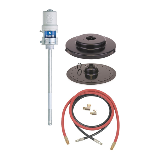
50:1 RATIO FIRE–BALL
Lubrication Pumps
Portable Units for Heavy Grease
5000 psi (35 MPa, 350 bar) Maximum Working Pressure
100 psi (0.7 MPa, 7 bar) Maximum Air Inlet Pressure
Important Safety Instructions.
Read all warnings and instructions in this manual.
Save these instructions. See page 2 for List of
Models and Table of Contents.
WARNING
These systems are designed to be used only in
pumping non-corrosive and non-abrasive lubricants
and greases. Any other use of the system can
cause unsafe operating conditions and result in
component rupture, fire, or explosion which can
cause serious injury, including fluid injection.
GRACO INC. P.O. BOX 1441 MINNEAPOLIS, MN 55440-1441
Copyright 1988, Graco Inc. is registered to I.S. EN ISO 9001
R
Model 240883 shown
307878V
01514A
Advertisement
Table of Contents

Related Manuals for Graco FIRE-BALL


Summary of Contents for Graco FIRE-BALL
- Page 1 Model 240883 shown 01514A GRACO INC. P.O. BOX 1441 MINNEAPOLIS, MN 55440-1441 Copyright 1988, Graco Inc. is registered to I.S. EN ISO 9001...
-
Page 2: Table Of Contents
..................Graco Standard Warranty . -
Page 3: Symbols
Symbols Warning Symbol Caution Symbol WARNING CAUTION This symbol alerts you to the possibility of serious This symbol alerts you to the possibility of damage to injury or death if you do not follow the instructions. or destruction of equipment if you do not follow the corresponding instructions. - Page 4 D This equipment is for professional use only. D Read all the instruction manuals, tags, and labels before operating the equipment. D Use the equipment only for its intended purpose. If you are uncertain about usage, call your Graco distributor.
-
Page 5: Installation
(Y). Fasten the screw back onto the pump and tighten securely. Connect the other end NOTE: Always use genuine Graco parts and of the wire to a true earth ground. To order a accessories, available from your Graco distributor. - Page 6 Installation Models 225773, 225827, 240883, 240884, and 245695 (Fig. 2) 1. Models 225773, 240883, and 245695 only: Assemble the truck as shown in the parts drawing on page 14. Secure the truck pail (5) to the truck base with the pointed hold-down clamps (3c) and thumbnuts (3d).
- Page 7 Installation Models 225006, 225026, 240880, 240881, and 245696 (Fig. 3) 2c, 2d 1. For Models 225006 and 240880: Assemble the base (3) as shown in the parts drawing on page 15. For Models 225026, 240881, 245696: Assemble the truck (3) as shown in the parts drawing on page 14.
- Page 8 Installation Models 222069, 240885, and 245694 (Fig. 4) 1. Remove the cover from the pail, and scoop the 4. Assemble the gun (2b) and hose (2a), and connect lubricant from the center to the sides of the pail to the hose to the pump fluid outlet. make its surface concave.
- Page 9 Installation Models 222245 and 240882 (Fig. 5) 1. Assemble the cart (6) as shown at right. Use only 2 of the 4 brackets (5d) supplied. Install the rear positions of the drum shelf (6b) as shown. 2. Place an open 120-lb drum of grease on the drum shelf.
- Page 10 Installation Models 226012 and 240886 (Fig. 6) 1. Assemble the truck as shown in the Parts Drawing on page 14 but do not assemble the handle. 2. Slide handle through elevator slide tube and secure handle to base. 3. Remove the fluid outlet adapter included with the pump, and screw the holster (6) into the pump outlet, using thread sealant.
- Page 11 Installation The installation shown below is only a guide for selecting and installing system components and accessories. Contact your Graco distributor for assistance in designing a system to suit your particular needs. Typical Installation Fluid dispense line Pump ground wire (required)
-
Page 12: Operation
Operation Pressure Relief Procedure 5. Set the air pressure to each pump at the lowest pressure needed to get the desired results. WARNING NOTE: A pump runaway valve can be installed on the air line to automatically shut off the pump if it INJECTION HAZARD starts to run too fast. -
Page 13: Parts
Includes items 1 to 6 Model 240884, 35- to 50-lb pail size Includes items 1 to 7 Part No. Description Qty. 239877 PUMP, 50:1 Fire-Ball; See manual 308883 for parts 222070 DISPENSE KIT; See parts list above 204134 PAIL 204574 COVER;... - Page 14 Includes items 1 to 6 Model 240881, 120-lb drum size Includes items 1 to 7 Part No. Description Qty. 239887 PUMP, 50:1 Fire-Ball See manual 308883 for parts 222070 DISPENSE KIT; See parts list on page 13 245697 DISPENSE KIT; (245696 only)
- Page 15 Includes items 1 to 6 Model 240880, 120-lb drum size Includes items 1 to 7 Part No. Description Qty. 239887 PUMP, 50:1 Fire-Ball See manual 308883 for parts 222070 DISPENSE KIT See parts list on page 13 203622 PORTABLE BASE...
- Page 16 Includes items 1 to 6 Model 240882, 120-lb drum size Includes items 1 to 7 Part No. Description Qty. 239887 PUMP, 50:1 Fire-Ball; See manual 308883 for parts 222383 DISPENSE KIT; See parts list above 222060 COVER; See manual 306345 for parts 220654 FOLLOW PLATE;...
- Page 17 Includes items 1 to 6 Model 240886, 50-lb pail size Includes items 1 to 7 Part No. Description Qty. 239877 PUMP, 50:1 Fire-Ball See manual 308883 for parts 222070 DISPENSE KIT; See parts list on page 13 203650 TRUCK, portable;...
-
Page 18: Sound Data
Sound Data See the pump instruction manual for technical data including wetted parts, port sizes, maximum air consumption, maximum delivery, and so on. Sound data for the air motors of the pumps on these portable units is as follows: Tested at 100 psi (0.7 MPa, 7 bar) at 40 cycles per minute Sound Pressure Level, measured at 1 meter from unit 77.9 dB(A) Sound Power Level, tested in accordance with ISO 9614–2... - Page 19 Notes 307878...
-
Page 20: Graco Standard Warranty
With the exception of any special, extended, or limited warranty published by Graco, Graco will, for a period of twelve months from the date of sale, repair or replace any part of the equipment determined by Graco to be defective.
Need help?
Do you have a question about the FIRE-BALL and is the answer not in the manual?
Questions and answers