Graco G3 Series Instructions Manual
Hide thumbs
Also See for G3 Series:
- Instructions manual (88 pages) ,
- Instructions (4 pages) ,
- Instruction manual (77 pages)
Table of Contents
Advertisement
Quick Links
Instructions
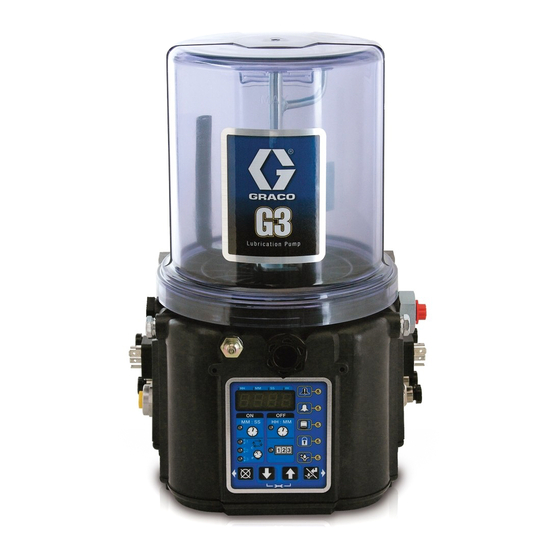
G3 Automatic
Lubrication Pump
For dispensing of NLGI Grades #000 to #2 greases.
Not approved for use in European explosive atmospheres. For Professional Use Only.
Part Nos., page 3
5100 psi (35.1 MPa, 351.6 bar) Maximum Working Pressure
Important Safety Instructions
Read all warnings and instructions in this
manual. Save these instructions.
3A0414B
ENG
Advertisement
Chapters
Table of Contents

Related Manuals for Graco G3 Series


Summary of Contents for Graco G3 Series
- Page 1 Instructions G3 Automatic 3A0414B Lubrication Pump For dispensing of NLGI Grades #000 to #2 greases. Not approved for use in European explosive atmospheres. For Professional Use Only. Part Nos., page 3 5100 psi (35.1 MPa, 351.6 bar) Maximum Working Pressure Important Safety Instructions Read all warnings and instructions in this manual.
-
Page 2: Table Of Contents
Mounting Pattern ......59 Graco Standard Warranty ....60... -
Page 3: Part / Model Numbers - 2 Liter Models
The Part Number is a six-digit unique number that is only used to order the G3 Pump. Directly related to this six digit Part Number is the configured Graco Model Number. This configured number identifies the distinct features of a spe- cific G3 Pump. -
Page 4: Understanding The Model Number
Use the Code Sample provided below to identify each component’s location in the Model Number. The options for each component that make up the code are provided on the lists below. NOTE: Some pump configurations are not available. Contact Graco Customer Service or your local Graco distributor for assistance. -
Page 5: Warnings
Warnings Warnings The following warnings are for the setup, use, grounding, maintenance, and repair of this equipment. The exclama- tion point symbol alerts you to a general warning and the hazard symbol refers to procedure-specific risk. When these symbols appear in the body of this manual, refer back to these warnings. Additional, product-specific warnings may be found throughout the body of this manual where applicable. - Page 6 Warnings WARNING PRESSURIZED EQUIPMENT HAZARD Over-pressurization can result in equipment rupture and serious injury. • A pressure relief valve is required at each pump outlet. • Follow Pressure Relief Procedure in this manual before servicing. PLASTIC PARTS CLEANING SOLVENT HAZARD Many solvents can degrade plastic parts and cause them to fail, which could cause serious injury or property damage.
-
Page 7: Installation
Pressure Relief Valve (Not included / required for each Power / Sensor Panel (both sides; only one side shown) outlet - Available from Graco. See Parts, page 53.) Part Number / Model Number example only shown, (see Zerk Inlet Fill Fitting (1 included) -
Page 8: Typical Installation
Installation Typical Installation Divider Installations Injector Installations Connected to fuse / power To lube points Pressure relief valve (Not included, required for each - Proximity Switch (Divider Installations) outlet - user supplied; see Parts, page 53) - Pressure switch (Injector Installations) - Cycle indicator sensor cable (Divider Installations) Vent valve - Pressure switch cable (Injector Installations) -
Page 9: Choosing An Installation Location
Installation Choosing an Installation Location AUTOMATIC SYSTEM ACTIVATION HAZARD Unexpected activation of the system could result in serious injury, including skin injection and amputation. This device has an automatic timer that activates the pump lubrication system when power is connected or when exit- ing the programming function. -
Page 10: System Configuration And Wiring
• it must be installed by a qualified electrician or ser- viceman. Fuse Kits are available from Graco. The following Table • it must be connected to a grounded,permenent wir- identifies the correct fuse to use for your input voltage ing system. - Page 11 An internal representative wiring diagram is included where it is deemed useful. Wire colors provided on these pages only refer to the power cable provided by Graco with this product. Standard Remote...
- Page 12 Installation Wiring and Installation Diagrams The following Table identifies the wiring and installation diagrams provided in this manual. Additional wiring diagrams for power cords and cables (described on the parts list, page 53) start on page 57. Diagram Symbol Page # Power DIN AC Power DIN DC Power CPC DC...
-
Page 13: Power Din Ac
Installation Power DIN AC Connector on Housing Pin-out (AC) 1 LINE Black 2 NEUTRAL White 3 Not Used Not Used 4 GROUND Green/Yellow Example Wiring Diagram Black White Green/Yellow 3A0414B... -
Page 14: Power Din Dc
Installation Power DIN DC NOTICE Be sure when power is applied that stirring paddle rotates clockwise (when viewed from the top). If it is wired incorrectly paddle could rotate counter-clockwise which will damage the pump’s internal components. If this happens, stop the pump immediately and wire unit correctly. -
Page 15: Power Cpc Dc
Installation Power CPC DC Connector on Housing Pin-out 1 Not Used Not Used - VDC Black 3 + VDC White 4 Not Used Not Used 5 Not Used Not Used Not Used 6 Not Used 7 Not Used Green/Yellow Example Wiring Diagram Ignition Switch Fuse 12V-pump - 7.5A... -
Page 16: Inputs
Installation Inputs Connector on Housing Pin-out 1 SW + 2 Not Used 3 SW - 4 Signal Example Wiring Diagram Dry Contacts Sink (NPN) 2 or 3 wire Source (PNP) 2 or 3 wire 3A0414B... -
Page 17: Vent Valve Outputs
Installation Vent Valve Outputs See Technical Data, page 57 for ratings. Connector on Housing Pin-out 1 Not Used 2 Relief+ 3 Relief - Example Wiring Diagram 3A0414B... -
Page 18: Alarm Outputs
Installation Alarm Outputs DC example shown. See Alarm Outputs, page 18 for functional description of alarm output. See Technical Data, page 57 for ratings. Connector on Housing Pin-out 1 N.O. 2 N.C. 3 COM 4 Not Used Example Wiring Diagram Alarm +9-30V 1 Amp Max Switch closes on alarm... -
Page 19: Low Level Outputs
Installation Low Level Outputs See Low Level Output Option, page 28 for functional description. Example Wiring Diagram 3A0414B... -
Page 20: Cable Wiring Diagrams
Installation Cable Wiring Diagrams Part No. 123749: 3-Wire Connector on Housing Pin-out 1 Not Used Not Used - VDC Black 3 + VDC White 4 Not Used Not Used 5 Not Used Not Used 6 Not Used Not Used 7 Not Used Green/Yellow Example Wiring Diagram Ignition Switch... - Page 21 Installation Part No. 123750: 5-Wire Connector on Housing Pin-out PIN Name Wire Color 1 Not Used - VDC Black 3 + VDC 4 LIGHT White 5 MANUAL Orange 6 Not Used 7 Not Used Green w/ Yellow Example Wiring Diagram 12V-pump - 7.5A Fuse 24V pump - 4A...
- Page 22 Installation Part No. 123358: DIN Connector on Housing Pin-out (AC) 1 LINE Black 2 NEUTRAL White 3 Not Used Not Used 4 GROUND Green/Yellow Example Wiring Diagram Black White Green/Yellow 3A0414B...
- Page 23 Installation Part No. 124300: Cable Pin Out Part No. 124333: Field Wireable Pin Out Wire Colors Wire Colors Item No. Color Item No. Color Brown Brown White White Blue Blue Black Black Cable Pin Out Field Wireable Pin Out Female End View Female End View Male End View 3A0414B...
-
Page 24: Setup
G3 pump it is installed on. See Technical Data, page 57. • Install a pressure relief valve close to every pump outlet; before any auxiliary fitting. NOTE: A pressure relief valve can be purchased from Graco. See Parts, page 54. 3A0414B... -
Page 25: Setting Pump Outlet Volume
• Before making any adjustments to pump volume, Relieve Pressure following procedure on page 24. • Only use Graco supplied spacers to control output volume. • It may be necessary to repeat this outlet volume setup procedure after the pump is operating to re-adjust the volume of dispensed grease. -
Page 26: Loading Grease
Setup Loading Grease For Max and Pro models press the manual run button. To ensure optimal performance from the G3: 3. Fill reservoir with NLGI grease to max • Only use NLGI #000 - #2 greases appropriate for fill line. your application, automatic dispensing, and the equipment’s operating temperature. -
Page 27: Priming
Setup majority of air is expelled from the reservoir and 2. Only run pump until air is no longer dispensed with grease comes out of the vent hole. the grease coming out of element fitting (F . 9). vent hole 3. -
Page 28: No Controller Operation
Pump ON (Run) time. If alternative NOTE: A low level warning is triggered when the con- ON / OFF times are required, contact Graco Cus- troller detects PINS 3 and 4 have momentarily closed. tomer Service for assistance. -
Page 29: Quick Setup Guide
Quick Setup Guide Quick Setup Guide Complete setup instructions for Pro Models begin on page 30 and Max Models begin on page 34. Pro Model System Enter Enter Enter Setup On Time Off Time MM:SS HH:MM System Prelube Runs Option According to Settings Enter... -
Page 30: Pro Model Setup
Pro Model Setup Pro Model Setup Control Panel Overview (F . 11) NOTE: Programming instructions begin on page 31. DISPLAY OFF TIME • A blinking LED under HH, MM, SS or ## • indicates type of measurement unit you LED lights when OFF Time sequence is are setting;... -
Page 31: Instructions
The G3 controller does not require a user to provide a PIN code to access the programming features of the Powering Units With Controllers unit. However, Graco understands that some users may By default, units with controllers are set to want to protect the program settings and therefore, an operate in a timed mode with 1 minute of option for adding PIN Code authorization is available. - Page 32 HH when pro- be updated. gramming hours OR MM when program- If this time does not meet the application needs, ming minutes. contact Graco Customer Support. • In SETUP MODE the number displayed in Programming ON Time the first field, on the...
- Page 33 Pro Model Setup 2. Press the ENTER button to lock in the 2. OFF displays. If you selection. The next HH number field to want the prelube the right flashes indicating it is ready for cycle to begin imme- programming. diately, leave this set to OFF.
-
Page 34: Max Model Setup
Max Model Setup Max Model Setup Control Panel Overview (F . 12) NOTE: Programming instructions begin on page 35. OFF TIME/BACKUP TIME • LED lights when OFF Time/Moni- DISPLAY tor sequence is used to control • A blinking LED under HH, MM, SS Pump OFF function. -
Page 35: Programming The Max Model
The G3 controller does not require a user to provide a PIN code to access the programming features of the • OFF, C1 (C2, C3) or unit. However, Graco understands that some users may P1 (P2, P3) displays, want to protect the programming settings and therefore, identifying the func- an option for adding PIN Code authorization is available. - Page 36 Max Model Setup • The first number dis- • If you are using more than played after the “C1” one sensor, use the UP or on the display blinks, DOWN arrow button to tog- indicating the device gle between OFF / C2 / P2. is ready to program the number of C1 NOTE: If C / P2 and C / P3 are not used, the default...
- Page 37 4. Press ENTER button to save the P2 stops. selection. To determine the Backup Time, Graco recommends the 5. Repeat steps 1 - 4 for P3 programming. user verify the length of time it takes to complete a typi- cal cycle and double that value (to a maximum of 30 Input Not Used minutes).
-
Page 38: Pump Off / Rest Setup
Max Model Setup 3. Use the UP or DOWN 3. When the correct number displays, ARROW button to scroll press the ENTER button to set the num- through numerals 0 to 9 until ber. the desired number appears NOTE: If the machine count input is available on the unit in the second MM number and not used, the value MUST be set to zero (0). - Page 39 Max Model Setup 1. After you set the Machine Count Backup Time field 9. Repeat steps 5 - 8 to set the SS (seconds) fields. and press the ENTER button, the G3 automatically 10. After pressing the ENTER button to set switches to the Prelube Delay setup.
-
Page 40: Advanced Programming
Advanced Programming Advanced Programming There are 5 Advanced Programming options. The following Table Identifies each option and when it is used. Advanced Model Setting Format/ Description Why Use This? Option Max / Pro Lockout Secures setup modes with Prevents unauthorized users to adjusting Code settings. - Page 41 Advanced Programming 2. Press the ENTER button to set the num- A2 - Low Level Alarm Time ber. The cursor automatically moves to Pump ON mode only. the next number field. Programs the amount of time in MM: SS (minutes and seconds) the pump can run between a Low Level Warn- 3.
- Page 42 Advanced Programming 3. Use the UP or DOWN • The small flashing ARROW button to scroll LED under the MM through numerals 0 to 9 until indicates you are the desired number appears setting Minutes. in the second MM number •...
- Page 43 The default setting is 0. For assistance determining a reasonable number of Alarm Retries to Fault and ON LED’s illuminate. program for your application, contact Graco Customer Service or your local Graco distributor. 1, 2, and 3 and Fault LED’s illuminate.
-
Page 44: Run Mode
Run Mode Run Mode • When the OFF Time count reaches zero, the G3 Automatic Lubrication Pump turns the pump on and it runs for the programmed ON Time cycle (F . 17). Time Control (Notice the ON Time LED is now illuminated on the After setup is complete, the G3 automatically begins to display.) run the OFF Time sequence (F... - Page 45 Run Mode Cycle (C1) / Pressure (P1) Control The display alternates between cycles (C1, C2, C3) or active sensor (P1, P2, P3) and time. • In Cycle Mode the lubrication period is ended by either: Cycle Control MM : SS HH : MM •...
- Page 46 Run Mode Prelube Delay • When the REST or OFF Cycle is complete, the G3 Pump runs for the programmed number of cycles or • If set for Prelube Delay, counts down to zero before until the pressure threshold is reached (F .
-
Page 47: Alarms
Alarms Alarms Any time a Fault / Warning occurs, a combination of LED’s will illuminate to notify you there is a problem and help identify the kind of Fault / Warning has occurred. • To clear an fault, press and hold the RESET button on the display button pad for 3 seconds. •... - Page 48 Alarms Cycle / System is over pressur- Examine system to deter- Pressure ized or a lubrication cycle mine if you have a Warning was not completed in the plugged or broken line or user-defined amount of other component failure, time. i.e., divider valve, injector.
- Page 49 Press and hold the RESET but- MM : SS HH : MM ton to clear warning. 1 2 3 System An internal fault has Contact Graco Customer Fault occurred. Service. MM : SS HH : MM 1 2 3 3A0414B...
-
Page 50: Troubleshooting
Maximum duty cycle is 33% (2 min- Adhere to allowable duty cycle. Con- utes OFF for each minute ON) tact Graco Customer Support if other Can’t set desired ON/OFF times duty cycles are required for applica- tion. - Page 51 Troubleshooting Problem Cause Solution Unit indicates a cycle or pressure The ON Time was not entered cor- Refer to programming ON Time, alarm before the lubrication cycle rectly pages 31 and 35. could complete In ON Time only, unit does not vent Vent valve time needs to be config- Refer to Advanced Programming to properly...
-
Page 52: Maintenance
Maintenance Maintenance Frequency Component Required Maintenance Daily and at refill Zerk Fittings Keep all fittings clean using a clean dry cloth. Dirt and/or debris can dam- age pump and/or lubrication system. Daily G3 Pump Unit and Reservoir Keep pump unit and reservoir clean using a clean dry cloth. -
Page 53: Parts
Parts Parts Part Description Part Description LABEL, controller blank, models BASE, three pump housing 16C473 96G000 - 96G008 LABEL, overlay, models 96G009, 278142 COVER, bottom, with seal 16A578 96G010 - 96G014, 115477 SCREW, mach, torx pan hd 96G027-96G029 LABEL, overlay, models O-RING, 258, included in Kit 16A073 96G015-9GG025,... - Page 54 Parts Pressure Relief Valves Part Description ◆ Important Information regarding Pressure Relief BAFFLE, low level, models Valve 16C807. 96G003, 96G005, 96G009, 96G011, 96G013, 96G015, 45† 24D838 Pressure Relief Valve 16C807 can only be used on 96G017, 96G019, 96G021, the G3 Pump. It is not intended for use with any other 96G023, 96G025, 96G030 - products.
- Page 55 Parts Fuses Part Description 571039 FUSE, 12 volt 571040 FUSE, 24 volt Installation and Repair Kits Kit No. Description 571026 KIT, output union, 3 pump 571063 KIT, output union, 2 pump KIT, return to reservoir, includes pressure 571028 relief valve 16C807 571029 KIT, vent valve, 24 volt KIT, vent valve, 12 volt 571061...
-
Page 56: Parts
Parts Parts Follower Plate Models Only 3A0414B... -
Page 57: Technical Data
Technical Data Technical Data Maximum Working Pressure 5100 psi (35.1 MPa, 351.6 bar) Power 100-240 VAC 88 - 264 VAC; 0.8 A current, 90 VA Power, 47/63 Hz, Single phase 12 V DC 9 - 16 VDC; 5 A current, 60 W 24 V DC 18 - 32 VDC;... - Page 58 Technical Data Pump Output 0.12 in. (2 cm ) / minute per outlet - 2 spacers 0.18 in. (3 cm ) / minute per outlet - 1 spacer 0.25 in. (4 cm ) / minute per outlet - 0 spacers Pump Outlet 1/4-18 NPSF.
-
Page 59: Mounting Pattern
Technical Data Mounting Pattern (All dimensions shown in inches. For correct mounting configuration, choose either Option 1 or Option 2). Option 1 .367 7.087 4x Ø .366 1.280 3.032 3.544 Option 2 .722 6.378 4x Ø .366 .708 3.740 3 189 . -
Page 60: Graco Standard Warranty
With the exception of any special, extended, or limited warranty published by Graco, Graco will, for a period of twelve months from the date of sale, repair or replace any part of the equipment determined by Graco to be defective.
Need help?
Do you have a question about the G3 Series and is the answer not in the manual?
Questions and answers