Table of Contents
Advertisement
Quick Links
Instructions
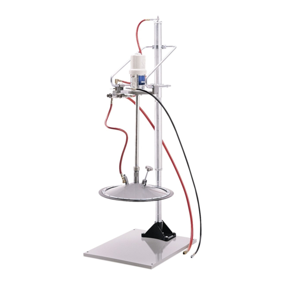
Topper Units
Grease dispense units with pneumatic pump elevator for easy drum replacement. For
professional use only.
Model No. 226013
®
50:1 Ratio Fire-ball
Pump
5000 psi (34.5 MPa, 345 bar) Maximum Working Pressure
100 psi (0.68 MPa, 6.89 bar) Maximum Air Pressure
Model No. 226018
®
50:1 Ratio President
Pump
4000 psi (27.6 MPa, 276 bar) Maximum Working Pressure
80 psi (0.55 MPa, 5.5 bar) Maximum Air Pressure
Model No. 244637
®
75:1 Ratio President
Pump
4000 psi (27.6 MPa, 276 bar) Maximum Working Pressure
80 psi (0.55 MPa, 5.5 bar) Maximum Air Pressure
Model No. 204490
without pump or hose kit
Model No. 25P544
36:1 Ratio GT 750 Pump
3600 psi (24.8 MPa, 248.2 bar) Maximum Working Pressure
100 psi (0.68 MPa, 6.89 bar) Maximum Air Pressure
Important Safety Instructions
Read all warnings and instructions in this
manual before using the equipment. Save
these instructions.
306556T
EN
Advertisement
Table of Contents


Need help?
Do you have a question about the Fire-Ball 425 Series and is the answer not in the manual?
Questions and answers