Table of Contents
Advertisement
Quick Links
Instructions
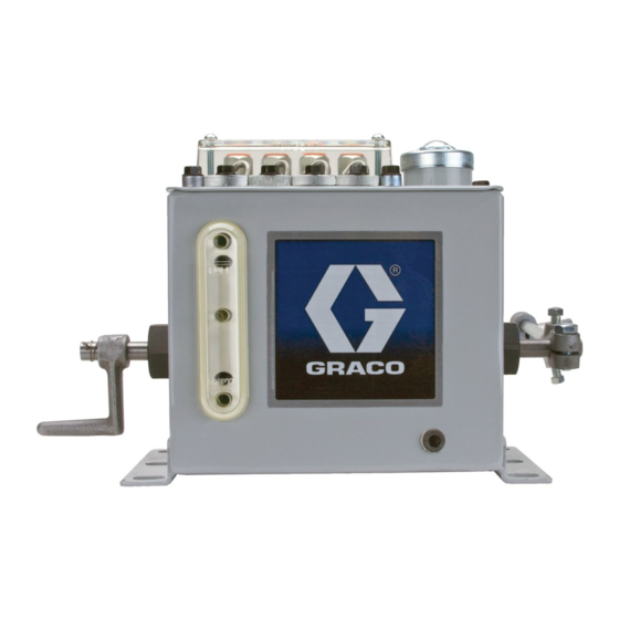
Model 25 Force
Feed Direct Rotary
Lubricator
Suction fed box lubricator for dispensing mineral oil-based or synthetic lubricants. For
professional use only.
Important Safety Instructions
Read all warnings and instructions in this
manual. Save these instructions.
See page 2 for model information
3A2099D
EN
Ex h T6 Gb
II 2 G
Advertisement
Table of Contents

Subscribe to Our Youtube Channel
Summary of Contents for Graco 25
- Page 1 Instructions Model 25 Force Feed Direct Rotary Lubricator 3A2099D Suction fed box lubricator for dispensing mineral oil-based or synthetic lubricants. For professional use only. Important Safety Instructions Read all warnings and instructions in this manual. Save these instructions. See page 2 for model information...
- Page 2 Approximate A = Right Max # of inch (cm) Model Capacity E = Left Pumps pints (liters) Right (A) Left (E) 6.25 (2.95) MAA†#A 7.59 (19.28) 8.84 (22.45) 6.25 (2.95) MAA†#E 7.59 (19.28) 8.84 (22.45) 9.25 (4.37) MAB†#A 11.59 (29.44) 12.84 (32.61)
- Page 3 Warnings Warnings The following warnings are for the setup, use, grounding, maintenance, and repair of this equipment. The exclama- tion point symbol alerts you to a general warning and the hazard symbols refer to procedure-specific risks. When these symbols appear in the body of this manual, refer back to these Warnings. Product-specific hazard symbols and warnings not covered in this section may appear throughout the body of this manual where applicable.
- Page 4 Warnings WARNING EQUIPMENT MISUSE HAZARD Misuse can cause death or serious injury. • Do not operate the unit when fatigued or under the influence of drugs or alcohol. • Do not exceed the maximum working pressure or temperature rating of the lowest rated system component.
-
Page 5: Installation
Installation Installation Component Identification Key: Sight feed cover Drip tube Feed regulator Pump mounting screws Metering plunger Pump crosshead Inlet tube Inlet strainer Sight chamber well Discharge plunger (shown at top of stroke) Reservoir Hand Crank Fill cover Drive shaft Sight glass Outlet Valve Metering Circuit 3A2099D... -
Page 6: Installation Procedure
Installation Grounding Start Up NOTE: Reference letters used in the following instruc- tions refer to Component Identification, page 5. 1. For initial start-up, prime the pump by removing The equipment must be grounded. Grounding screw from outlet metering circuit (S) (F . -
Page 7: Pressure Relief Procedure
Service Service Hand Crank Operation The hand crank (M), located on the end of the lubricator . 3) is used for starting or for momentarily increasing Pressure Relief Procedure the lubricant supply while the lubricator is in operation. It operates all feeds at once, but does not affect feed regu- lation. - Page 8 Service a. Remove the discharge line connection and the Reassembly pump mounting screws (D) (F . 5). 1. Before replacing pump, position yoke down as far as possible (F . 7). b. Loosen the adjacent pump mounting screws 2. Install pump by inserting the back end of the pump (D).
-
Page 9: Troubleshooting
Troubleshooting Troubleshooting Problem Cause Solution 1. Flush discharge check valves. Pump sight well fills and Dirty or inoperative pump overflows into adjacent discharge valves a. Turn feed regulator to full open. sight wells b. Operate hand crank rapidly. 2. Remove discharge check valves if condition still exists. a. - Page 10 Parts Parts Top View 18/19 Pump (7) Ref Part No. Description Ref Part No. Description SCREW, #10-32 x 1.50 (1-4 pumps) 562949 PUMP, assembly, 0.187 diameter M25 SCREW, #10-32 x 1.50 (5-8 pumps) 562950 PUMP, assembly, 0.312 diameter M25 SCREW, #10-32 x 1.50 (9-12 pumps) SCREW, 1/4-20X.75 hex SCREW, #10-32 x 1.50(13-16 pumps) SCREWS (1-4 pumps)
- Page 11 Parts 31 - Blank Plate Quantity Based on Number of Pumps (Code column relates to Pump Quantity, see page 2) Code # of Code A Picks Pumps 3A2099D...
-
Page 12: Technical Data
Technical Data Technical Data Maximum operating pressure 1000 psi (6.89 MPa, 68.9 bar) Drive Speed 3 to 60 RPM Number of drops per stroke 5/16 inch model: maximum 12 drops 5/16 inch model: minimum 1/4 drop 3/16 inch model: maximum 6 drops 3/16 inch model: minimum 1/6 drop... - Page 13 (215.9) 16-19/32 17-27/32 9 - 12 (421.4) (453.1) (6.1) 6.50 20-19/32 21-27/32 (165.1) 13 - 16 (523) (554.7) (7.5) RESER VOIR 25-19/32 26-27/32 19-3/4 17 - 20 (650) 681.7) (9.3) (8.1) 6.00 (152.4) Inches (mm) 4.25 (107.9) "B" "A" FULL 0.50...
-
Page 14: Graco Standard Warranty
With the exception of any special, extended, or limited warranty published by Graco, Graco will, for a period of twelve months from the date of sale, repair or replace any part of the equipment determined by Graco to be defective.


Need help?
Do you have a question about the 25 and is the answer not in the manual?
Questions and answers