Table of Contents
Advertisement
Quick Links
Instructions-Parts List
™
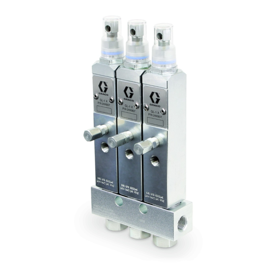
GL-1 X
Injectors
For Single–Line Parallel Automatic Lubrication Systems
Important Safety Instructions
Read all warnings and instructions in this manual and in related Automatic Lubrication System instruction
manuals. Save all instructions.
Maximum Working Pressure:
Models:
See page 2
GL-1 X Model
, GL-1 XL
6000 psi (41 MPa, 414 bar)
™
GL-1 XL Model
335023J
EN
Advertisement
Table of Contents

Subscribe to Our Youtube Channel
Related Manuals for Graco GL-1 X


Summary of Contents for Graco GL-1 X
- Page 1 Important Safety Instructions Read all warnings and instructions in this manual and in related Automatic Lubrication System instruction manuals. Save all instructions. Maximum Working Pressure: 6000 psi (41 MPa, 414 bar) Models: See page 2 GL-1 X Model GL-1 XL Model...
- Page 2 Models GL-1 X Injector Models Bare Manifold Part No. Description Dimension A* Dimension B* Part No. Injector, GL-1 X, one point 2.48 in. (63.0 mm) 114911 24X801 Injector, GL-1 X, two point 3.00 in. (76.0 mm) 114912 24X802 Injector, GL-1 X, three point 1.25 in.
- Page 3 Warnings Warnings The following warnings are for the setup, use, grounding, maintenance, and repair of this equipment. The exclamation point symbol alerts you to a general warning and the hazard symbols refer to procedure-specific risks. When these symbols appear in the body of this manual or on warning labels, refer back to these Warnings. Product-specific hazard symbols and warnings not covered in this section may appear throughout the body of this manual where applicable.
-
Page 4: Installation Instructions
(c). 2. Slide the o-ring (d) over the indicator stem of the injector and into the groove. 3. Slide cap (c) down over the indicator stem of the injector. groove . 1: GL-1 X model injector shown 335023J... - Page 5 (2) clockwise, to reduce output. To adjust, loosen lock nut (3) and turn adjusting screw (2) the num- ber of turns indicated on the GL-1 X or GL-1 XL Volume Output Guide to obtain the desired volume. Tighten lock...
- Page 6 Installation Instructions 335023J...
- Page 7 Plunger with guide (GL-1 XL models) Poppet valve (GL-1 X models) Packing, FKM Inlet valve Backup ring, UHMWPE Packing, FKM Bonded washer Manifold Steel gasket Adapter bolt Included in GL-1 XL Injector Repair Kit 25A080 Included in GL-1 X Injector Repair Kit 25A081 335023J...
-
Page 8: Available Kits
Available Kits Spacer Kits - 10 Pack: See below for Graco Part No. and Page 9 for Spacer Installation Instructions. Use Only Genuine Graco Repair Parts GL1-X Spacer Kit Table Graco Part No. 17L754: Clear Polycarbonate Output Target Output Target Ratio... - Page 9 Injector Service Parts Spacer Installation Instructions 4. Reinstall adjustment screw in injector. Hand tighten securely. 1. Relieve pressure. See Pressure Relief Procedure, in the pump instruction manual included with your automatic lubrication system. 2. Remove adjusting screw (2) and jam nut (3) from injector.
-
Page 10: Technical Data
Suggested operating pressure 2500 psi (17 MPa, 172 bar) Reset pressure 1000 psi (6.9 MPa, 69 bar) Output volume per cycle GL-1 X adjustable 0.01 to 0.07 in. GL-1 XL adjustable 0.04 to 0.30 in. Wetted parts carbon steel, stainless steel, fluoroelastomer, UHMWPE Recommended fluids N.L.G.I. - Page 11 Technical Data Dimensions 1.25 in. (31.75 mm) GL-1 X Model 1/8 NPT dispense outlet 8.53 in. (219.2 mm) 3/8 in. NPT (2) supply inlet/outlet 13/32 in. mounting holes GL-1 XL Model 1.25 in. (31.75 mm) 1/8 in. NPT dispense outlet 11.22 in.
-
Page 12: Graco Information
With the exception of any special, extended, or limited warranty published by Graco, Graco will, for a period of twenty-four months from the date of sale or up to 100,000 lube cycles, which ever comes first, repair or replace any part of the equipment determined by Graco to be defective.
Need help?
Do you have a question about the GL-1 X and is the answer not in the manual?
Questions and answers