Table of Contents
Advertisement
Quick Links
Instructions - Parts List
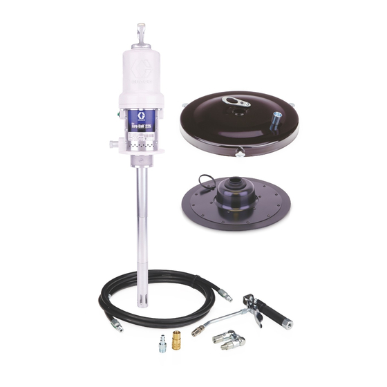
Mini Fire-Ball
50:1 Grease Pump
Packages
Portable units for dispensing heavy grease.
See page 2 for model numbers.
5000 psi (34 MPa, 345 bar) Maximum Working Pressure
100 psi (0.7 MPa, 7 bar) Maximum Air Working Pressure
Important Safety Instructions
Read all warnings and instructions in this manual.
Save these instructions.
Contents
Models . . . . . . . . . . . . . . . . . . . . . . .2
Warnings . . . . . . . . . . . . . . . . . . . . .3
Operation/Service . . . . . . . . . . . . . .4
Installation . . . . . . . . . . . . . . . . . . .5
Operation . . . . . . . . . . . . . . . . . . .11
Parts . . . . . . . . . . . . . . . . . . . . . . .12
Sound Data . . . . . . . . . . . . . . . . . .18
Graco Standard Warranty . . . . . .20
Graco Information . . . . . . . . . . . .20
Graco Inc. P.O. Box 1441 Minneapolis, MN 55440-1441
Copyright 2007, Graco Inc. is registered to I.S. EN ISO 9001
®
225,
Model 253388 shown
309967A
253388
Advertisement
Table of Contents

Related Manuals for Graco Mini Fire-Ball 225 Series


Summary of Contents for Graco Mini Fire-Ball 225 Series
-
Page 1: Table Of Contents
Sound Data ....18 Graco Standard Warranty ..20 Graco Information ... .20 253388 Model 253388 shown Graco Inc. -
Page 2: Models
Models Models Model Dispense Hose/Fitting Base Follow CE Kit Size Kit 236058 Kit 222072 Type Cover Plate Handle Pail 240979 ✔ ✔ 246910 35-50 lb 222059 220653 (16-23 kg) ✔ ✔ ✔ 253384† 35-50 lb 222059 220653 (16-23 kg) ✔ 253362 35-50 lb 222059... -
Page 3: Warnings
Read fluid and solvent manufacturer’s warnings. For complete information about your material, request MSDS forms from distributor or retailer. • Check equipment daily. Repair or replace worn or damaged parts immediately with genuine Graco replacement parts only. •... -
Page 4: Operation/Service
Operation/Service WARNING FIRE AND EXPLOSION HAZARD When flammable fluids are present in the work area, such as gasoline and windshield wiper fluid, be aware that flammable fumes can ignite or explode. To help prevent fire and explosion: • Use equipment only in well ventilated area. •... -
Page 5: Installation
Fluid supply container: follow local code. drawing. To maintain grounding continuity when flushing or Always use genuine Graco parts and accessories, relieving pressure: hold metal part of the dispense available from your Graco distributor. valve firmly to the side of a grounded metal pail, then trigger the valve. - Page 6 Installation Typical Installation The installation shown below is only a guide for selecting and installing system components and accessories. Con- tact your Graco distributor for assistance in designing a system to suit your particular needs. Key: A Fluid dispense line...
- Page 7 Installation Models 246910, 253362, and 253384 (F . 2) through the follow plate grommet. The pump stop plate(4b) will secure the pump in place. 1. Remove the cover from the pail, and scoop the lubricant from the center to the sides of the pail to 4.
- Page 8 Installation Models 246911, 246913, 253385 and 253386 4. Secure the cover (4) on the pail with the three thumbscrews (A). . 3) 1. Remove the fluid outlet adapter included with the 5. Insert the pump riser tube through the top of the pump, and screw the holster (6) into the pump outlet cover (4).
- Page 9 Installation Models 246914, 246917, 253387 and 253390 . 4 and F . 5) 1. Remove the cover from the pail, and scoop the lubricant from the center to the sides of the pail to make its surface concave. 2. Center the follow plate (5) in the pail opening. Press the follow plate firmly downward and rotate it over the lubricant surface to eliminate air pockets and prevent channeling.
- Page 10 Installation Models 246915, 246916, 253388 and 253389 . 6) 1. For Models 246915 and 253388: Assemble the por- 2c, 2d table base (8) as shown in the parts drawing on page 17 For Models 246916 and 253389: Assemble the truck (7) as shown in the parts drawing on page 17. 2.
-
Page 11: Operation
Operation Operation Pressure Relief Procedure A pump runaway valve can be installed on the air line to automatically shut off the pump if it starts to run too fast. Never allow the pump to run dry of the fluid being pumped. -
Page 12: Parts
Parts Parts Models 246910, 253362, and 253384 35-50 lb (16-23 kg) pail size Ref. No. Part No. Description Qty. 246909 PUMP, Mini Fire-Ball 225 50:1 (with handle) See manual 309966 for parts. 253361 PUMP, Mini Fire-Ball 225 50:1 (without handle) Model 253362 See manual 309966 for parts. - Page 13 Parts Models 246913 and 253386 35-50 lb (16-23 kg) pail size Ref. No. Part No. Description Qty. 246909 PUMP, Mini Fire-Ball 225 50:1 See manual 309966 for parts. 236058 DISPENSE KIT; 12 ft (3.7 m) hose; See parts list on page 16. 204574 COVER See manual 306345 for parts.
- Page 14 Parts Models 246915 and 235388 120 lb 55 kg) drum size Ref. No. Part No. Description Qty. 246780 PUMP, Mini Fire-Ball 225 50:1 See manual 309966 for parts. 236058 DISPENSE KIT; 12 ft (3.7 m) hose; See parts list on page 16. 204574 COVER See manual 306345 for parts.
- Page 15 Parts Models 246917 and 253390 400 lb (180 kg) drum size Ref. No. Part No. Description Qty. 246781 PUMP, Mini Fire-Ball 225 50:1 See manual 309966 for parts. 222072 Hose and Fitting Kit; 6 ft (1.8 m) hose; See parts list on page 16. 200326 COVER See manual 306345 for parts.
- Page 16 Parts Ref. No. 2, Dispense Kit 236058 Ref. No. Part No. Description Qty. 109151 HOSE; 1/4 npt(mbe) x 12 ft (3.7 m) 242056 VALVE, grease dispense See manual 309032 114558 COUPLER, quick-disconnect 169971 NIPPLE, quick-disconnect 202577 Z-SWIVEL 236058 Ref. No. 3, Hose and Fitting Kit 222072 Ref.
- Page 17 Parts Ref. No. 7, Truck 203650 Ref. No. Part No. Description Qty. 203651 BASE, truck; bare 101251 WHEEL 159912 NUT, thumb, 5/16-18 159913 CLAMP, hold down; (for steel drums only) 154636 WASHER, 5/8”, 16 GA 100609 SCREW, machine, panhead; 1/4-20 x 0.375”...
-
Page 18: Sound Data
Sound Data Sound Data See the pump instruction manual for technical data including wetted parts, port sizes, maximum air consumption, maximum delivery, and so on. Sound data for the air motors of the pumps on these portable units is as follows: Tested at 140 psi (1.0 MPa, 10 bar) at 100 cycles per minute Sound Pressure Level, measured at 1 meter from unit 77.8 dB(A) - Page 19 309967A...
-
Page 20: Graco Standard Warranty
With the exception of any special, extended, or limited warranty published by Graco, Graco will, for a period of twelve months from the date of sale, repair or replace any part of the equipment determined by Graco to be defective.
Need help?
Do you have a question about the Mini Fire-Ball 225 Series and is the answer not in the manual?
Questions and answers