Advertisement
Quick Links
Instructions – Parts List
R ,
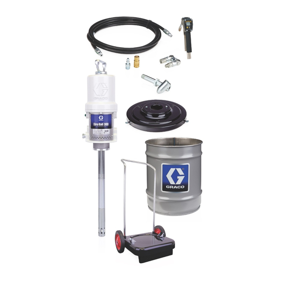
50:1 Fire-Ball
50:1 President
Topper Units
For use with lubricating products only.
Model 226013, 50:1 Ratio Fire-Ball
5000 psi (34.5 MPa, 350 bar) Maximum Fluid Working Pressure
100 psi (0.7 MPa, 7 bar) Maximum Air Pressure
Model 226018, 50:1 Ratio President
4000 psi (28 MPa, 280 bar) Maximum Fluid Working Pressure
80 psi (0.6 MPa, 5.6 bar) Maximum Air Pressure
Model 244637, 75:1 Ratio President
4000 psi (28 MPa, 280 bar) Maximum Fluid Working Pressure
80 psi (0.6 MPa, 5.6 bar) Maximum Air Pressure
Model 204490, Elevator and Inductor
without pump or hose kit
Important Safety instructions
Read all warnings and instructions in this manual.
Save these instructions.
GRACO INC. P.O. BOX 1441 MINNEAPOLIS, MN 55440-1441
Copyright 1996, Graco Inc. is registered to I.S. EN ISO 9001
R
, and 75:1 President
R
Pump
R
Pump
R
Pump
R
400-lb. drum size
306556R
0719
Advertisement

Subscribe to Our Youtube Channel
Related Manuals for Graco Fire-Ball Series


Summary of Contents for Graco Fire-Ball Series
- Page 1 Model 204490, Elevator and Inductor without pump or hose kit Important Safety instructions Read all warnings and instructions in this manual. Save these instructions. 0719 GRACO INC. P.O. BOX 1441 MINNEAPOLIS, MN 55440-1441 Copyright 1996, Graco Inc. is registered to I.S. EN ISO 9001...
- Page 2 D This equipment is for professional use only. D Read all instruction manuals, tags, and labels before operating the equipment. D Use the equipment only for its intended purpose. If you are not sure, call your Graco distributor. D Do not alter or modify this equipment.
- Page 3 WARNING SKIN INJECTION HAZARD Spray from the gun, leaks or ruptured components can inject fluid into your body and cause extremely serious injury, including the need for amputation. Fluid splashed in the eyes or on the skin can also cause serious injury. D Fluid injected into the skin is a serious injury.
- Page 4 WARNING FIRE AND EXPLOSION HAZARD Improper grounding, poor ventilation, open flames, or sparks can cause a hazardous condition and result in a fire or explosion and serious injury. D Ground the equipment and the object being sprayed. Refer to Grounding on page 6. D If there is any static sparking or you feel an electric shock while using this equipment, stop spray- ing immediately.
- Page 5 Notes 306556...
- Page 6 Installation NOTE: Reference numbers and letters in parentheses in the text refer to the callouts in the figures and the parts drawing. NOTE: Always use Genuine Graco Parts and Accessories, available from your Graco distributor. Grounding WARNING TI1052 Fig. 1...
- Page 7 It is not an 1. Secure the elevator base (A) to the mounting base actual system design. Contact your Graco (102), using the screws (104), lockwashers (103), representative for assistance in designing a system to and nuts (105).
- Page 8 Installation Mounting the Pump Models 226013, 226018, and 244637 1. Mount the pump on pump support bracket (86). 2. Remove inductor plate nut (11 or 24), locking ring (8 or 23) and O–ring (9). See Fig. 3. 3. In order, slide inductor plate nut (11 or 24), locking ring (8 or 23) and O–ring (9) on pump riser tube.
- Page 9 Installation Installing the Hoses and Valves NOTE: Use thread sealant on all male threads except 4. Install a bleed-type master air valve on the pump’s at the swivel unions. air supply line. See the Typical Installation on page 7. 1. Remove the plug from the top of the elevator cap, and screw it into the air inlet (E) in the elevator WARNING base.
- Page 10 Operation 10. Press down on the pump and rock it back and CAUTION forth to seat the inductor plate. This helps eliminate air trapped beneath the plate. Continue Always close the ball valve (65) as soon as the this action until fluid appears at the vent inductor plate reaches the bottom of the drum, opening (D).
- Page 11 Operation Removing a Drum 3. Open the snap-over valve (27) and raise the elevator to full height. WARNING NOTE: If you lose air pressure when reaching the drum chime, continue holding the air-assist valve and To reduce the risk of serious injury whenever you slowly pull out the snap-over valve until the chime is are instructed to relieve pressure, always follow the passed.
- Page 12 Service Reinstalling the Pump CAUTION Follow the steps at left in reverse order. When To avoid contaminating the fluid in the supply con- attaching the pump to the inductor plate, turn the tainer, keep the pump intake and the inductor plate locking nut (11 or 24) the same number of turns noted clean during the servicing operations.
- Page 13 Parts Model 204490 Model 244637 Elevator and Inductor Plate Assembly Pump, Elevator & Inductor Plate Assembly Includes items 17, 25, 90, and 101 Includes items 21, 25, 90, 97, 101, and 107 Ref. Ref. Part No. Description Qty. Part No. Description Qty.
- Page 14 Parts Ref. No. 1: Part No. 204353 Inductor Plate Assembly: 400 lb drum size Fits 50:1 Fire-Ball In-Line Pump; Includes items 2 –16 Ref. Part No. Description Qty. 204502 PLATE, inductor, bare 100015 NUT, hex, mscr; 1/4–20 UNC-2a Tapered 100021 CAPSCREW, hex hd;...
- Page 15 Notes 306556...
- Page 16 Parts Ref. No. 27 Ref. No. 42 29 36 Snap-Over Valve Assembly Restrictor Valve Assembly Includes items 28 to 40 Includes items 43 to 46 1/8 npt 0729 0730 0732B 66 74 Ref. No. 47 Air Assist Valve Assembly Includes items 48 to 60 3/8 npt 1/4 npt 0731...
- Page 17 Parts Ref. No. 25; Part No. 204461 Ref. Wishbone Support Assembly Part No. Description Qty. Ref. 160402 . HOUSING, valve Part No. Description Qty. 160404 . STUD, valve 204560 HOSE, air; cpld 3/8 npt(m) 202295 SNAP-OVER VALVE ASSY. 3/8” (9.6 mm) ID; 18” (457 mm) long Includes items 28 to 40 204561 HOSE, air;...
- Page 18 Parts Ref. No. 91; Part No. 204467 Ref. No. 97; Part No. 205102 Fire-Ball Delivery Hose Kit President Delivery Hose Kit Includes items 92 to 96 and 115 Includes items 94 to 96, 98, 99, 110, and 111 Ref. Ref. Part No.
- Page 19 Sound Data See the pump instruction manual for technical data including wetted parts, port sizes, maximum air consumption, maximum delivery, and so on. Sound data for the pumps on these units are as follows: 50:1 Fire-Ball Pumps Tested at 100 psi (0.7 MPa, 7 bar) at 40 cycles per minute Sound Pressure Level, measured at 1 meter from unit 77.8 dB(A) Sound Power Level, tested in accordance with ISO 9614–2...
- Page 20 With the exception of any special, extended, or limited warranty published by Graco, Graco will, for a period of twelve months from the date of sale, repair or replace any part of the equipment determined by Graco to be defective.
Need help?
Do you have a question about the Fire-Ball Series and is the answer not in the manual?
Questions and answers