
Related Manuals for Graco Progressive Series


Summary of Contents for Graco Progressive Series
- Page 1 Series Progressive Lubrication • COMPONENT INSTALLATION • TUBING AND PIPE CLEANING • SYSTEM LUBRICANT PREFILLING...
- Page 2 Series Progressive Lubrication Systems Installation Guide L40000 INTRODUCTION When installing a Series-Progressive lubrication system, System installation procedures for specific com ponents utilized the installer must have a copy of the lu brication schematic in a series-progressive lubrication system are detailed in the diagram that was developed when the system was designed.
-
Page 3: General Installation Guidelines
Series Progressive Lubrication Systems Installation Guide L40000 GENERAL INSTALLATION GUIDELINES The positioning and orientation of components rel ative to each a check valve and plug, should be installed at the highest other is essential to ensure the cor rect function and operation point of the header line, i.e., at the end point furthest from of any centralized lu brication system. -
Page 4: Mounting The Pump
Series Progressive Lubrication Systems Installation Guide L40000 MOUNTING THE PUMP All pump and reservoir package combinations incorporate a method for attaching them to a suit able mounting surface. The pump should be located such as to make it the lowest component in the lubrication system. - Page 5 Other mounting variations may require the use of a mounting plate interface. Graco has several styles of mounting plates available for straightforward installations. Also, a customized design can be developed for those installations that require special considerations and hardware.
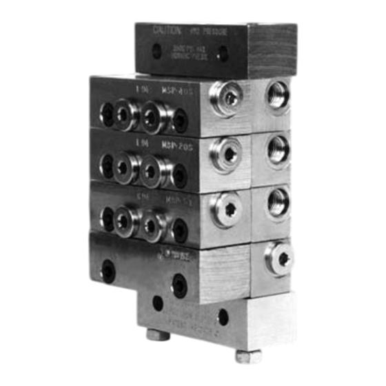
- Page 6 Series Progressive Lubrication Systems Installation Guide L40000 INSTALLING CHECK VALVES In systems utilizing header lines, check valves should be placed upstream and in close proximity to all Zero-Leak solenoid valves that control the lubricant input to the master feeder valve assem blies. This prevents the lubricant in the line from draining out should a lubrication point fitting re quire loosening or disconnecting (see Figure 7).
- Page 7 Series Progressive Lubrication Systems Installation Guide L40000 INSTALLING TUBING, PIPES, AND HOSES The lubrication system schematic diagram speci fies the type of tubing, pipes, or hose to be used to connect the various system components. The ba sic rule to remember and follow is to keep all lines as short as possible with a minimum number of bends that are consistent with ease of installation and removal.
- Page 8 Series Progressive Lubrication Systems Installation Guide L40000 INSTALLING TUBING, PIPES, AND HOSES (continued) • Keep tubing away from walkways or areas where it could present a safety hazard or be damaged by pedestrian or vehicular traffic (see Figure 12). When installing the tubing, take into consideration how the machine will be operated and serviced.
- Page 9 Series Progressive Lubrication Systems Installation Guide L40000 INSTALLING TUBING, PIPES, AND HOSES (continued) • Use a deburring tool to remove all burrs from the bore of all tubing sections that have been cut (see Figure 16). • Make sure all fittings are properly tightened to recommended torque levels to prevent small leaks or weeping of lubricant.
- Page 10 Series Progressive Lubrication Systems Installation Guide L40000 Component Flushing Procedure This procedure is designed to flush each piece of tubing free of contaminants before it is installed into the system. The procedure consists of the following seven steps: Use a properly-sized stiff stainless steel wire brush to loosen existing contaminants from the tube inside diameter, extending as far as possible into any bends in the tubing (see Fig ure 17).
- Page 11 However, levels of cleanliness and filtration. Graco’s products, as well as those provided by other manufacturers of fluid-handling components, can operate at their optimum design capability only when supplied with properly cleaned and filtered fluids and lubricants.
- Page 12 Series Progressive Lubrication Systems Installation Guide L40000 LUBRICANT FILTRATION REQUIREMENTS (continued) Figure 22 demonstrates several examples of the types of filters recommended for use in lubricant dispensing systems and their proper locations within the system. Proper selection and location of filters will ensure compliance with the bearing or machine tool manufacturer’s cleanliness require ments for maintaining the operating specifications and warranty.
- Page 13 Series Progressive Lubrication Systems Installation Guide L40000 PREFILLING THE SYSTEM WITH LUBRICANT • Filling the lines connecting the master divider valve to the Once the lubrication system installation has been completed, secondary divider valves. it is necessary to prefill all of the lines (tubing/pipes/hoses) •...
- Page 14 Figure 24 Figure 25 All written and visual data contained in this document are based on the latest product information available at the time of publication. Graco reserves the right to make changes at any time without notice. Contact us today! To receive product information or talk with a Graco representative, call 800-533-9655 or visit us online at www.graco.com.
Need help?
Do you have a question about the Progressive Series and is the answer not in the manual?
Questions and answers