Advertisement
Quick Links
Advertisement

Related Manuals for Enwork Landing


Summary of Contents for Enwork Landing
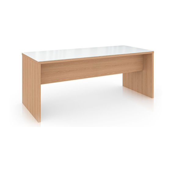
- Page 1 Landing Laminate Team Table Installation Instructions Rev A 7/30/18...
- Page 2 INSTALLATION GUIDE 1) Parts and Fasteners Included 24mm Cam Dowel 8mm x 1in Dowel Pins Keel Block Top Surface Keel End Panel...
- Page 3 INSTALLATION GUIDE 1) Parts and Fasteners Included Optional Foot Bar Parts Angle Bracket 5/16 Flange Nut #10 x 1 Phillips Screw Foot Bar Weldment...
-
Page 4: Tools And Supplies Required
INSTALLATION GUIDE 2) Tools and Supplies Required Phillips Head Screw Driver Rubber Mallet Phillips Drive Cordless Drill Ratchet 5/16 Deep Socket... - Page 5 INSTALLATION GUIDE Keel Sub Assembly 4) Assembly: Fig. 1 Install (4) Cam Dowels Pins into the (4) 5mm pre drilled holes on the Keel. Repeat for second Keel. Fig. 1 Fig. 2 Assemble Keel Block and Keels. Keel Blocks should be assembled with the Cam Dowel surfaces facing each other (as shown).
-
Page 6: Base Sub Assembly
INSTALLATION GUIDE Base Sub Assembly 4) Assembly: Fig. 4 Install (4) Cam Dowels Pins & (6) 8mm Dowels Pins into (10) centrally located pre drilled holes on the End Panel. Repeat for second End Panel. Fig. 4 Fig. 5 Align the Cams Dowels and Dowel Pins and assemble the (2) End Panels and the Keel Sub Assembly. -
Page 7: Top Assembly
Fig. 8 Align the (4) 8mm Cam Dowel Pins and Cams and assemble the Top Surface and the Base Sub Assembly. Cam the Top Surface and the Base Sub Assembly together. Level the Landing Table using the End Panel Levelers. Fig. 8... - Page 8 INSTALLATION GUIDE Optional Foot Bar Assembly 4) Assembly: Fig. 9 Attach Angle Bracket to End Panel using (4) #10- 1 Phillips Screw. Use predrilled holes. Repeat for opposite End Panel. Fig. 9 Fig. 10 Attach foot Bar Weldment using (2) 5/16 Flange Nuts.
- Page 9 12900 Christopher Drive Lowell, MI 49331 800.815.7251 www.enwork.com Specifications subject to change without notice.
Need help?
Do you have a question about the Landing and is the answer not in the manual?
Questions and answers