Table of Contents
Advertisement
Quick Links
Advertisement
Table of Contents

Subscribe to Our Youtube Channel
Related Manuals for Insportline Omahan ET


Summary of Contents for Insportline Omahan ET
- Page 1 USER MANUAL – EN IN 20302 Elliptical trainer inSPORTline Omahan ET...
-
Page 2: Table Of Contents
CONTENTS SAFETY INSTRUCTIONS ........................3 PRODUCT DESCRIPTION ........................4 ASSEMBLY ............................. 6 CONSOLE ............................. 11 PROGRAMS ............................12 USE OF ELEPTICAL TRAINER ......................15 THE WARM UP PHASE ........................15 MAINTENANCE ............................ 16 ENVIRONMENT PROTECTION ......................16 DIAGRAM .............................. 17 PARTS LIST ............................ -
Page 3: Safety Instructions
SAFETY INSTRUCTIONS • To ensure the best safety of the exerciser, regularly check it on damages and worn parts. • If you pass on this exerciser to another person or if you allow another person to use it, make sure that that person is familiar with the content and instructions in these instructions. •... -
Page 4: Product Description
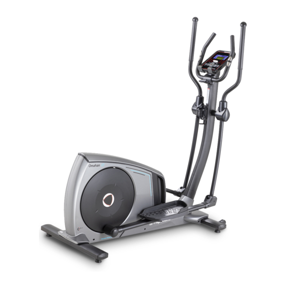
PRODUCT DESCRIPTION 1. Handlebars 2. Console 3. Pulse sensor 4. Bottle holder 5. Main frame 6. Middle post 7. Transport wheels 8. Front stabilizer 9. Pedals 10. Rear stabilizer TECHNICAL SPECIFICATIONS Dimensions 1660 x 720 x 1580 mm Maximal load capacity 150 kg Speed ratio 10.3... - Page 5 35. Ø10x45xM6x20 – 2 38. ST4 x 16 – 2 pcs 29. M8x20 – 4 pcs 38. ST4x16 – 2 pcs 26. M10x70x20 – 4 pcs Allen key 103. Ø17 – 2 pcs 39. M12x60 – 2 pcs Name Specification Qty.
-
Page 6: Assembly
ASSEMBLY STEP 1 Attach the front stabilizer (2) to the main frame (1) with arc washer (28), spring washer (27) and an Allen screw (26). STEP 2 Attach the rear stabilizer (3) to the main frame (1) with arc washer (28), spring washer (27) and an Allen screw (26). - Page 7 STEP 3 Connect the motor communication cable (11) and the column communication cable (12). Attach the middle post (4) to the main frame (1). Remove the caps (102). Then fasten with Allen screws (39) and cover with caps (102). Tighten the screws properly.
- Page 8 STEP 4 Lubricate the handles (25) and washers (103). Then attach the handles L and R (5 and 6) to the left and right axes (25). Secure with washer (31) and Allen screw (29). Attach the caps (17 and 16) to the handles (5 and 6) with the screws (34). STEP 5 Lubricate the axes on the main frame (1) and then attach the pedal bracket (7) using the washer (31) and the Allen key (29).
- Page 9 STEP 6 Attach the handles (9). Route the cables (13) through the center post (4). Attach the hand screw (41) to the handle cover (40). Do not tighten yet. Attach the bottle holder (24) to the center column (4) with the screw (33). STEP 7 Attach the console communication cables (12) to the back of the console.
- Page 10 STEP 8 Attach the handlebar caps (22 and 23) to the center post (4) with the screws (34). Attach the handlebar front cover (40) with the screws (101). Adjust the handlebar height with the hand screw. STEP 9 Attach the AC adapter.
-
Page 11: Console
CONSOLE BUTTONS START/STOP Start / stop program RESET If a program is paused or you are setting up values, returns to the menu Hold for 2 seconds, the console will restart and start user settings UP (+) Increase value MODE/ENTER Confirm settings, enter settings DOWN (-) Decrease value... -
Page 12: Programs
Pic. 3 Pic. 4 PROGRAMS MANUAL will flash in the main menu. Select the program with the UP (+) / DOWN (-) buttons and confirm with the ENTER button. Programs go in the order: MANUAL - PROGRAM - USER PROGRAM - H.R.C –... - Page 13 Press the START / STOP button to start the program. During the program, the user can use the UP (+) / DOWN (-) buttons to set the load from 1 to 16. Press the START / STOP button to pause the program. Press RESET to return to the main menu. H.R.C PROGRAM Use the UP (+) / DOWN (-) keys to select a program, select H.R.C (Pic.
- Page 14 BODY FAT PROGRAM During training, press START / STOP to stop the program and press BODY FAT (Pic. 11) to turn on the measurement. Grasp the sensors on the handles. After 8 seconds, console displays BMI, FAT% (fat percentage) Press BODY FAT again to return to the menu. E-1 (Pic.
-
Page 15: Use Of Eleptical Trainer
Pic. 14 Pic. 15 Excellent 1,0 <F <2,0 Above average 2,0<F <2,9 Good 3,0<F <3,9 Average 4,0<F <5,9 Below the average NOTES: • Console has a 9V, 1300 mA adapter. • If the user stops pedaling for 4 minutes, the console enters Sleep mode. All data and settings are saved until next run. -
Page 16: Maintenance
Upper thigh Lean against a wall with one hand. Reach down and behind you. Lift up your right or left foot to your buttock as high as possible. Keep for 30 seconds and repeat twice for each leg. Hamstring stretched Sit and outstretch your right leg. -
Page 17: Diagram
DIAGRAM... -
Page 19: Parts List
PARTS LIST Name Name Screw M4×10 Main frame 0.74 m Front stabilizer PT50×100×t1.5×600 Allen screw Φ10×45×M6×20 Rear stabilizer PT50×100×t1.5×700 Flat washer Φ6 Allen screw M6×15 Middle post 0.27m Screw ST4×16 Handlebar (L) 0.161 m Handlebar (R) 0.161 m Allen screw M12×60 Front handlebar cover 89×73.5×35 Pedal holder (L) 0.2 m Hand screw M8×30... -
Page 20: Terms And Conditions Of Warranty, Warranty Claims
Crank axle sleeve 1 Φ25×Φ20.1×4.6 Bearings 6200-2RS Crank axle sleeve 3 Φ40×Φ20.1×7.7 Foam grip Φ36×t3.0×720 Crank axle Φ20×115 End cap Φ32×t1.5 Belt pulley Φ308×22 Motor cover L 1291.1×72×616.2 Crank axle sleeve 2 Φ25×Φ20.1×10.2 Motor cover R 1291.1×75.9×616.2 Screw ST4×25 Magnet set Magnetic control fixed axle Φ12×50 Circlip for holes Φ40 Brake spring Φ11.5×Φ1.2×13... - Page 21 Warranty Period The Seller provides the Buyer a 24 months Warranty for Goods Quality, unless otherwise specified in the Certificate of Warranty, Invoice, Bill of Delivery or other documents related to the Goods. The legal warranty period provided to the Consumer is not affected. By the Warranty for Goods Quality, the Seller guarantees that the delivered Goods shall be, for a certain period of time, suitable for regular or contracted use, and that the Goods shall maintain its regular or contracted features.
- Page 22 26847264 VAT ID: CZ26847264 Phone: +420 556 300 970 E-mail: eshop@insportline.cz reklamace@insportline.cz servis@insportline.cz Web: www.inSPORTline.cz inSPORTline s.r.o. Headquaters, warranty & service center: Električná 6471, Trenčín 911 01, SK CRN: 36311723 VAT ID: SK2020177082 Phone: +421(0)326 526 701 E-mail: objednavky@insportline.cz reklamacie@insportline.cz servis@insportline.cz...
Need help?
Do you have a question about the Omahan ET and is the answer not in the manual?
Questions and answers