Table of Contents
Advertisement
Quick Links
Advertisement
Table of Contents

Subscribe to Our Youtube Channel
Related Manuals for Insportline Omahan ET


Summary of Contents for Insportline Omahan ET
- Page 1 USER MANUAL – EN IN 20302 Elliptical trainer inSPORTline Omahan ET...
-
Page 2: Table Of Contents
CONTENTS SAFETY INSTRUCTIONS ........................3 PRODUCT DESCRIPTION ........................4 ASSEMBLY ............................. 7 CONSOLE ............................. 12 USE ..............................13 USE OF ELLIPTICAL TRAINER ......................18 THE WARM UP PHASE ........................18 MAINTENANCE ............................ 19 ENVIRONMENT PROTECTION ......................19 DIAGRAM .............................. 20 PARTS LIST ............................ -
Page 3: Safety Instructions
SAFETY INSTRUCTIONS • To ensure the best safety of the exerciser, regularly check it on damages and worn parts. • If you pass on this exerciser to another person or if you allow another person to use it, make sure that that person is familiar with the content and instructions in these instructions. •... -
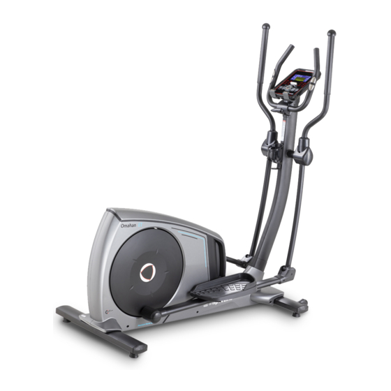
Page 4: Product Description
PRODUCT DESCRIPTION 1. Handlebars 2. Console 3. Pulse sensor 4. Bottle holder 5. Main frame 6. Middle post 7. Transport wheels 8. Front stabilizer 9. Pedals 10. Rear stabilizer TECHNICAL SPECIFICATIONS Dimensions 1660 x 720 x 1580 mm Maximal load capacity 150 kg Speed ratio 10.3... - Page 5 ASSEMBLY MATERIAL...
- Page 6 Name Specification Qty. M10×70×20 Allen screw Φ10 Spring washer Φ10 Flat washer M8×20 Allen screw Φ8.5×Φ20×t1.5 Flat washer Lock nut M4×16 Screw M4×10 Allen screw Φ10×45×M6×20 Allen screw Φ6 Flat washer Allen screw M6×15 Bolt ST416 Aleen bolt M10x20 ST4×12 Screw Allen bolt M10x55x20...
-
Page 7: Assembly
ASSEMBLY STEP 1 Attach the front stabilizer (2) to the main frame (1) with arc washer (28), spring washer (27) and an Allen screw (26). STEP 2 Attach the rear stabilizer (3) to the main frame (1) with arc washer (28), spring washer (27) and an Allen screw (26). - Page 8 STEP 3 Connect the motor communication cable (11) and the column communication cable (12). Attach the middle post (4) to the main frame (1) with flat washer (28), spring washer (27), Allen bolt (39), curved washer (107), spring washer (29) , Allen bolt (39), Allen bolt (102), curved washer (107) and nut (32).
- Page 9 STEP 4 Lubricate the handles (25) and washers (103). Then attach the handles L and R (5 and 6) to the left and right axes (25). Secure with washer (31) and Allen screw (29). Attach the caps (17 and 16) to the handles (5 and 6) with the screws (34). STEP 5 Lubricate the axes on the main frame (1) and then attach the pedal bracket (7) using the washer (31) and the Allen key (29).
- Page 10 STEP 6 Attach the handles (9). Route the cables (13) through the center post (4). Attach the hand screw (41) to the handle cover (40). Do not tighten yet. Attach the bottle holder (24) to the center column (4) with the screw (33). STEP 7 Attach the console communication cables (12) to the back of the console.
- Page 11 STEP 8 Attach the handlebar caps (22 and 23) to the center post (4) with the screws (34). Attach the handlebar front cover (40) with the screws (101). Adjust the handlebar height with the hand screw. STEP 9 Attach the AC adapter.
-
Page 12: Console
CONSOLE Buttons Increase load / navigation key Down Decrease load / navigation button Mode / Enter Confirm settings or selections Holding the button for 2 seconds resets the setting / entering the setting / Reset returning to the main menu in the setting or pausing mode Start / Stop Starts or stops the device Recovery... -
Page 13: Use
Turn on Connect the device to the socket, the console will start, and all the data will be displayed for 2 seconds (Fig. 1). Fig. 1 Program selection Use the UP and DOWN buttons to select the manual program (Fig. 2) - beginner (Fig. 3) - advanced (Fig. - Page 14 Fig. 8 Manual program Press "Start" on the home page to enter the manual mode and start the program. Use the "Up" and "Down" buttons to select the manual mode and confirm with "Mode / Enter". Use the "Up" and "Down" buttons to set the time (Fig. 9), distance (Fig. 10), calories (Fig. 11), heart rate (Fig.
- Page 15 Beginner Use the "Up" and "Down" buttons to select the beginner and confirm with "Mode / Enter". Use the "Up" and "Down" buttons to select mode 1 - 4 (Fig. 14) and confirm with "Mode / Enter". Use the "Up" and "Down" buttons to set the time. Press "Start / stop"...
- Page 16 Fig. 16 Cardio Use the "Up" and "Down" buttons to select H.R.C and confirm with "Mode / Enter". Use the "Up" and "Down" buttons to set the age (Fig. 17). Use the "Up" and "Down" buttons to select 55% (Fig. 18), 75%, 90% or TAG (user setting, original value: 100).
- Page 17 Use the "Up" and "Down" buttons to set the profile (Fig. 20). The user must set 20 parts, in each of which he must set the resistance. During the setting, the user can exit the setting by pressing the "Mode / Enter" button for 2 seconds. Use the "Up"...
-
Page 18: Use Of Elliptical Trainer
Fig. 25 Fig. 26 ERROR MESSAGES E-1: heart rate not detected E-4: % of body fat and BMI is below 5 or above 50 (Fig. 27) Fig. 27 NOTE: The device switches to standby mode if it is not used for 4 minutes. Press any button to wake up the device. -
Page 19: Maintenance
Touching your toes Slowly bend your back from hips. Keep your back and arms relaxed while stretching downwards to your toes. Do it as far as you are able and hold the position for 15 seconds. Bend your knees slightly. Upper thigh Lean against a wall with one hand. -
Page 20: Diagram
DIAGRAM... -
Page 23: Parts List
PARTS LIST Name Name Screw M4×10 Main frame 0.74 m Front stabilizer PT50×100×t1.5×600 Allen screw Φ10×45×M6×20 Rear stabilizer PT50×100×t1.5×700 Flat washer Φ6 Allen screw M6×15 Middle post 0.27m Screw ST4×16 Handlebar (L) 0.161 m Handlebar (R) 0.161 m Allen bolt M10x20 Front handlebar cover 89×73.5×35 Pedal holder (L) 0.2 m Hand screw M8×30... -
Page 24: Terms And Conditions Of Warranty, Warranty Claims
Crank axle sleeve 1 Φ25×Φ20.1×4.6 Bearings 6200-2RS Crank axle sleeve 3 Φ40×Φ20.1×7.7 Foam grip Φ36×t3.0×720 Crank axle Φ20×115 End cap Φ32×t1.5 Belt pulley Φ308×22 Motor cover L 1291.1×72×616.2 Crank axle sleeve 2 Φ25×Φ20.1×10.2 Motor cover R 1291.1×75.9×616.2 Screw ST4×25 Magnet set Magnetic control fixed axle Φ12×50 Circlip for holes Φ40 Brake spring Φ11.5×Φ1.2×13... - Page 25 Warranty Period The Seller provides the Buyer a 24 months Warranty for Goods Quality, unless otherwise specified in the Certificate of Warranty, Invoice, Bill of Delivery or other documents related to the Goods. The legal warranty period provided to the Consumer is not affected. By the Warranty for Goods Quality, the Seller guarantees that the delivered Goods shall be, for a certain period of time, suitable for regular or contracted use, and that the Goods shall maintain its regular or contracted features.
- Page 26 26847264 VAT ID: CZ26847264 Phone: +420 556 300 970 E-mail: eshop@insportline.cz reklamace@insportline.cz servis@insportline.cz Web: www.inSPORTline.cz inSPORTline s.r.o. Headquaters, warranty & service center: Električná 6471, Trenčín 911 01, SK CRN: 36311723 VAT ID: SK2020177082 Phone: +421(0)326 526 701 E-mail: objednavky@insportline.cz reklamacie@insportline.cz servis@insportline.cz...
Need help?
Do you have a question about the Omahan ET and is the answer not in the manual?
Questions and answers