Keysight Technologies E6640A Getting Started Manual
Wireless test set
Hide thumbs
Also See for E6640A:
- Getting started manual (148 pages) ,
- Installation manual (12 pages) ,
- Manual (2606 pages)
Table of Contents
Advertisement
Quick Links
Advertisement
Table of Contents

Related Manuals for Keysight Technologies E6640A


Summary of Contents for Keysight Technologies E6640A
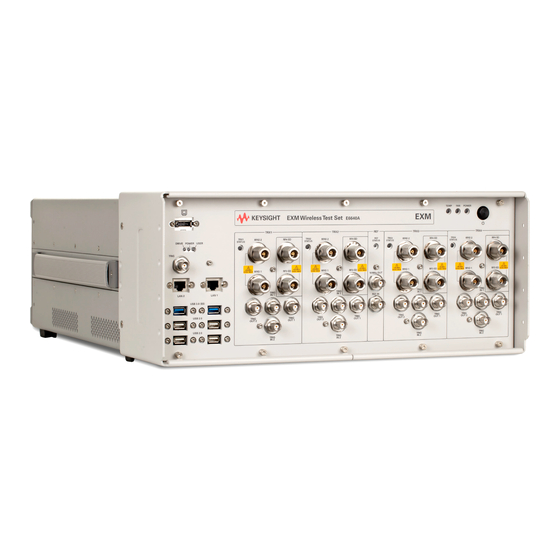
- Page 1 Keysight Wireless Test Set E6640A Wireless Test Set Getting Started Guide...
- Page 2 COVERING THE MATERIAL IN THIS DOCUMENT THAT CONFLICT WITH government requirements THESE TERMS, THE WARRANTY beyond those set forth in the © Keysight Technologies, Inc. TERMS IN THE SEPARATE EULA shall apply, except to the 2014-2019 AGREEMENT WILL CONTROL. extent that those terms, rights, or...
- Page 3 Where to Find the Latest Information Documentation is updated periodically. For the latest information about these products, including instrument software upgrades, application information, and product information, browse to one of the following URLs, look for the name of your product: https://www.keysight.com/en/pd-3008067/5g-non-signaling-manufacturing-test-solution?nid=-33762.1 271218&cc=US&lc=eng To receive the latest updates by email, subscribe to Keysight Email Updates at the following URL:...
-
Page 5: Table Of Contents
Contents Table of Contents Quick-Start 11 About the Test Set 12 Elements of the TRX 13 Input/Output Matrix (M9432A, Option 2FD) 14 Input/Output Matrix (M9433A, Option 4FD) 15 Initial Inspection 16 Shipping problems? 17 Test Set Location and Mounting Requirements 18 Locating the test set 18 Cooling and rack mounting 18 Separate Application Interfaces 19... - Page 6 Weekly alignment procedure 56 TRX Selection 57 Using HiSLIP 57 Using Socket Ports 58 Using VXI-11/SICL 58 Using Telnet Connection 58 E6640A Calibration Status 59 Certificates of Calibration 60 Desktop Icons 61 TRX Configurator 62 Launch XSA 63 Configure XSA Applications 64...
- Page 7 Weekly alignment procedure 108 TRX Selection 109 Using HiSLIP 109 Using Socket Ports 110 Using VXI-11/SICL 110 Using Telnet Connection 110 E6640A Calibration Status 111 Certificates of Calibration 112 Desktop Icons 113 TRX Configurator 114 Launch XSA MultiTouch 115 Configure Applications MultiTouch 116...
- Page 8 Contents User Accounts 130 Administrator login 130 User login 130 Customer creation of accounts 131 Licensing 132 Licensed Applications 132 Flexible Software Licensing 133 Licensing New Measurement Application Software - After Initial Purchase 134 Installation procedure over USB 134 Transporting a License Between Test Sets 136 Procedure for Transporting a License, Neither Test Set Connected to the Internet 136 Windows Configuration 139 Settings that can be changed 139...
- Page 9 Check the Basics 186 Problems with Microsoft Windows Operating System 188 Returning a test set for Service 189 Read the Warranty 189 Service Options 189 Calling Keysight Technologies 189 Locations for Keysight Technologies 189 Packaging the Test Set 190 Getting Started Guide...
- Page 10 Contents Getting Started Guide...
-
Page 11: Quick-Start
Keysight Wireless Test Set E6640A EXM Wireless Test Set Getting Started Guide Quick-Start This section explains how to initialize the test set and generate and view a signal. “About the Test Set” on page 12 “Initial Inspection” on page 16 “Test Set Location and Mounting Requirements”... -
Page 12: About The Test Set
Quick-Start About the Test Set About the Test Set The E6640A EXM Wireless Test set contains one to four Keysight M943xA TRXs. The specific TRX model number is dependent on the options and applications ordered with the test set: — M9432A (Option 2FD) has 2 half-duplex and 2 full-duplex ports. -
Page 13: Elements Of The Trx
Quick-Start About the Test Set Elements of the TRX Each TRX contains the full set of hardware elements illustrated below. Two separate examples are shown, for models M9432A (Option 2FD) and M9433A (Option 4FD). Figure 1-1 TRX elements Each TRX is run by its own instance of the XSA firmware application. A fully loaded test set shows four independent XSA windows on its monitor display. -
Page 14: Input/Output Matrix (M9432A, Option 2Fd)
Quick-Start About the Test Set Input/Output Matrix (M9432A, Option 2FD) The input/output matrix is illustrated below, for the M9432A TRX. Ports RFIO 1 and RFIO2 are full-duplex ports (simultaneously inputs and outputs). Ports RF3 I|O and RF4 I|O can be inputs or outputs, but not simultaneously. Figure 1-2 M9432A input/output matrix “Port Configuration”... -
Page 15: Input/Output Matrix (M9433A, Option 4Fd)
Quick-Start About the Test Set Input/Output Matrix (M9433A, Option 4FD) The input/output matrix is illustrated below, for the M9433A TRX. Ports RFIO 1 through RFIO4 are full-duplex ports (simultaneously inputs and outputs). . Figure 1-3 M9433A input/output matrix “Port Configuration” on page 118 for more information about port setup in connection with the 5G NR application. -
Page 16: Initial Inspection
Initial Inspection Inspect the shipping container and the cushioning material for signs of stress. Retain the shipping materials for future use, as you may wish to ship the test set to another location or to Keysight Technologies for service. Item Deliverable... -
Page 17: Shipping Problems
— Contact the nearest Keysight Technologies office. — Keep the shipping materials for the carrier’s inspection. — If you must return an test set to Keysight Technologies, use the original (or comparable) shipping materials. See “Returning a test set for Service” on page 183. -
Page 18: Test Set Location And Mounting Requirements
Quick-Start Test Set Location and Mounting Requirements Test Set Location and Mounting Requirements Locating the test set Make sure that the fan inlet and exhaust vent areas on the sides, bottom, and back of the test set chassis are not obstructed. The minimal required clearance is 1 inch (25 cm). -
Page 19: Separate Application Interfaces
Quick-Start Separate Application Interfaces Separate Application Interfaces There are two different interfaces for test applications which run on the EXM. The interfaces are launched separately, using either the LaunchXSA or LaunchXSA MultiTouch icons on the desktop. (The two interfaces cannot run simultaneously.) Many EXM setup procedures are performed differently, depending on which of the two interfaces is running. - Page 20 Quick-Start Separate Application Interfaces The interface associated with the LaunchXSA MultiTouch icon is illustrated below. Figure 1-6 XSA MultiTouch interface Getting Started Guide...
-
Page 21: Turning On The Test Set The First Time
2 Connect a monitor Connect the monitor to the Model E6640A has no display; an external monitor is monitor port on the front panel required. of the test set. “Virtual Front Panel” on page 28... - Page 22 Quick-Start Turning on the test set the first time Steps Actions Notes The analyzer performs the following steps: • Windows Startup window • Black screen • Windows message window, “Please wait while windows prepares to setup” • Keysight window At this time, it is safe to turn off the instrument before initializing the software. After launching the setup, do not turn off the instrument or remove power before the Setup Wizard completes and the system restarts.
- Page 23 Quick-Start Turning on the test set the first time Steps Actions Notes 7 Verify the installation From the mouse right-click If you require further assistance, contact the Keysight Utility Virtual support team. menu, select Online assistance: http://www.keysight.com/find/assist Front Panel . (All key-presses that follow refer initially to a key shown on the Virtual Front Panel, and then to whatever...
- Page 24 Quick-Start Turning on the test set the first time Steps Actions Notes The 2.4 GHz signal appears on the display. Getting Started Guide...
-
Page 25: Options And Licenses
Quick-Start Options and Licenses Options and Licenses The options and licenses installed on the test set are listed on the System > Show > System display, as illustrated below. Certain features of the test set (such as its frequency range, its analysis bandwidth, the measurement applications it runs, and in some cases individual measurements within an application) are licensed features, and are unavailable if the appropriate license is not installed. -
Page 26: Option 2Fd
(providing an RF stimulus). — Performance characteristics for all four ports are same as those described for ports RFIO 1 and RFIO 2 in the E6640A EXM Wireless Test Set Data Sheet. — Port settings under the Input/Output menu (and equivalent SCPI commands) are modified to reflect the option installed. -
Page 27: Frequency Range Options
1.1 to 1.8, 2.3 to 2.6, and 4.8 to 6 GHz (wireless connectivity) Option E6640A-506 380 MHz to 6 GHz (cellular communications and wireless connectivity) Option E6640A-5B0 (required for 5G NR testing) 380 MHz to 6 GHz with 5G NR bands (cellular communications and wireless connectivity) -
Page 28: Anti-Virus Software And Firewalls
Quick-Start Anti-Virus Software and Firewalls Anti-Virus Software and Firewalls No anti-virus software is shipped with the test set. It is recommended that you install anti-virus software if your test set is connected to the LAN. Check with your IT department to see what they recommend. The test set is shipped with the Windows firewall enabled. -
Page 29: Instrument Safety & Environmental Information
Quick-Start Instrument Safety & Environmental Information Instrument Safety & Environmental Information Power requirements The only physical installation of your Keysight test set is a connection to a power source. Line voltage does not need to be selected. This test set does not contain customer serviceable fuses. This is a Safety Class 1 Product (provided with a protective earthing ground incorporated in the power cord). -
Page 30: Environmental Conditions (Operating)
Quick-Start Instrument Safety & Environmental Information AC power cord The test set is equipped with a three-wire power cord, in accordance with international safety standards. This cable grounds the test set cabinet when connected to an appropriate power line outlet. The cable appropriate to the original shipping location is included with the test set. -
Page 31: Ventilation
Quick-Start Instrument Safety & Environmental Information Ventilation VENTILATION REQUIREMENTS: When installing the product in a cabinet, the convection into and out of the product must not be restricted. The ambient temperature (outside the cabinet) must be less than the maximum operating temperature of the product by 4oC for every 100 watts dissipated in the cabinet. - Page 32 See “Returning a test set for Service” on page 183. Replaceable parts must be approved or supplied by Keysight Technologies. You can order the service documentation for the instrument through your Keysight Sales and Service office. Danger of explosion if battery is incorrectly replaced. Replace only with the same or equivalent type recommended.
-
Page 33: Protecting Against Electrostatic Discharge
Quick-Start Instrument Safety & Environmental Information Protecting against electrostatic discharge Electrostatic discharge (ESD) can damage or destroy electronic components (the possibility of unseen damage caused by ESD is present whenever components are transported, stored, or used). Test equipment and ESD To help reduce ESD damage that can occur while using test equipment: Do not use these first three techniques when working on circuitry with a voltage potential greater than 500 volts. - Page 34 Quick-Start Instrument Safety & Environmental Information Getting Started Guide...
-
Page 35: Front And Rear Panel Features
Keysight Wireless Test Set E6640A EXM Wireless Test Set Getting Started Guide 2 Front and Rear Panel Features The following topics can be found in this section: “Front Panel Features” on page 36 “Rear Panel Features” on page 49 “Front and Rear Panel Symbols” on page 50... -
Page 36: Front Panel Features
Front and Rear Panel Features Front Panel Features Front Panel Features The test set consists of instruments loaded in a PXI rack, hidden behind a front panel. There is a controller (located on the far left), and one to four TRX (transmit/receive) sub-instruments, each of which includes an RF signal generator and an RF signal analyzer. -
Page 37: Controller Hardware Interface
— DRIVE: When the Solid State Drive is active, the LED will flash. — POWER: If the LED is on, the power supply to the controller is good and the system should boot. — USER: Not used. TRIG This trigger line is not used by the E6640A. Getting Started Guide... - Page 38 Front and Rear Panel Features Front Panel Features Number Item Name Description LAN Connectors Two TCP/IP Interface connectors that are used for remote test set operation. Choose the LAN 1 port to have an IP address assigned to the test set dynamically, using DHCP.
-
Page 39: Trx Module Hardware Interface
There can be as many as four TRX modules in the PXI rack; each has the same hardware interface, as illustrated below. If the E6640A test set was purchased with Option 4FD, all four RF ports have full-duplex capability, therefore two of the ports are labeled and used differently than they are described below. - Page 40 Front and Rear Panel Features Front Panel Features Number Item Name Description TRIG OUT 2 A trigger output used to synchronize other test equipment with the test set. Configurable from the Input/Output keys. TRIG IN 1 A trigger input used to synchronize other test equipment with the test set. Configurable from the Input/Output keys.
-
Page 41: Reference Module Hardware Interface
Front and Rear Panel Features Front Panel Features Reference Module Hardware Interface The connectors which are exposed when the impact cover is in place are illustrated below: Figure 2-4 Reference module front panel Number Item Name Description 10 MHz OUT This BNC input port provides a timebase reference output from the M9300A Reference module. -
Page 42: Virtual Front Panel
2. Left-click Utility (1) in the menu, as shown below. 3. Left-click Virtual Front Panel (2) in the menu, as shown below. The PC mouse and monitor are required when using the E6640A. For ease in using the VFP, the PC keyboard is recommended. - Page 43 Front and Rear Panel Features Front Panel Features Figure 2-6 Virtual front panel keys Getting Started Guide...
-
Page 44: When The Test Set Is Controlled Remotely
Front and Rear Panel Features Front Panel Features When the Test Set is Controlled Remotely The test set can be controlled remotely, from another computer. (See “Remote Desktop: Using the Test Set Remotely” on page 163.) When the test set is being controlled remotely, a log-on screen is displayed on the monitor. -
Page 45: Display Annotations (Xsa Interface)
The TRX sub-instrument associated with the application (identified as “TRX1” through “TRX4”). This is needed because the E6640A can include up to four independent TRX sub-instruments in one PXI rack. Getting Started Guide... - Page 46 Front and Rear Panel Features Front Panel Features Number Description Function Key Banner; shows the name of the selected application Mode that is currently running. Measurement title; shows title information for the Meas current measurement, or a title that you created for View/Display, Display, Title the measurement.
-
Page 47: Display Annotations (Xsa Multitouch Interface)
Display annotations (XSA MultiTouch interface) Number Description Notes The TRX sub-instrument associated with the This is needed because the E6640A can include up to four application (identified as “TRX1” through independent TRX sub-instruments in one PXI rack. “TRX4”). Screen tab. Shows mode and measurement To change the selection, click on the tab to open the selected for that tab. - Page 48 Front and Rear Panel Features Front Panel Features Number Description Notes Preset icon. Access to presets and defaults. Left side of measurement bar; includes display The following graphics indicate single/continuous of pass/fail result, plus single/continuous measurement: measurement selection and indicator. Measurement results.
-
Page 49: Rear Panel Features
+3.3 VDC, (5) Inhibit [Low], (6) +12 VDC, (7) Rsrvd, (8) -12 VDC, (9) Logic Gnd. 10 MHz REF OUT This BNC connector is not used by the E6640A test set. The front panel 10 MHz OUT connector should be used instead. 10 MHz REF IN This BNC connector is not used by the E6640A test set. -
Page 50: Front And Rear Panel Symbols
Front and Rear Panel Features Front and Rear Panel Symbols Front and Rear Panel Symbols Symbol Description This symbol is used to indicate power ON. This symbol is used to indicate power OFF. This symbol is used to indicate power STANDBY mode (yellow in standby, green when instrument is ON). - Page 51 Front and Rear Panel Features Front and Rear Panel Symbols Symbol Description This symbol indicates separate collection for electrical and electronic equipment mandated under EU law as of August 13, 2005. All electric and electronic equipment are required to be separated from normal waste for disposal (Reference WEEE Directive 2002/96/EC).
- Page 52 Front and Rear Panel Features Front and Rear Panel Symbols Getting Started Guide...
-
Page 53: Xsa Interface
The following topics can be found in this section: “Distinguishing the Interfaces” on page 54 “Alignments” on page 55 “TRX Selection” on page 57 “E6640A Calibration Status” on page 59 “Desktop Icons” on page 61 “Port Configuration” on page 66 “LAN Address Configuration” on page 103 “Switched MIMO”... -
Page 54: Xsa Interface
XSA Interface Distinguishing the Interfaces Distinguishing the Interfaces The most visible difference between the interfaces is in the menus in the rightmost column of the display. Figure 3-1 XSA Interface and XSA MultiTouch UI The XSA interface relies on a combination of submenus and a Virtual Front Panel popup window. -
Page 55: Alignments
XSA Interface Alignments Alignments Alignments are internal calibration adjustments which each TRX module must make to ensure that internal signal levels are properly maintained. To avoid interruptions, the alignments are not run automatically, either at startup or afterward; you must run them explicitly. “All”... -
Page 56: Weekly Alignment Procedure
XSA Interface Alignments Weekly alignment procedure A more thorough alignment of the source and analyzer in the TRX is required on a weekly basis. This procedure is similar to the “All” alignment described above, but it also performs additional alignment functions related to slow-drifting parameters which do not change significantly over time periods shorter than a week. -
Page 57: Trx Selection
The means of identifying a TRX depends upon the connection method, as outlined below. Using HiSLIP HiSLIP (High-Speed LAN Instrument Protocol) is the recommended interface for connection to the E6640A, because of its superior performance characteristics. Use hislip0 through hislip3: — TRX1: TCPIP0::<IP Address>::hislip0::INSTR —... -
Page 58: Using Socket Ports
XSA Interface TRX Selection Using Socket Ports Use sockets 5025, 5125, 5225, and 5325: Using VXI-11/SICL Use inst0 through inst3: — TRX1: TCPIP0::<IP Address>::inst0::INSTR — TRX2: TCPIP0::<IP Address>::inst1::INSTR — TRX3: TCPIP0::<IP Address>::inst2::INSTR — TRX4: TCPIP0::<IP Address>::inst3::INSTR Using Telnet Connection Use telnet ports 5023, 5123, 5223, 5323: —... -
Page 59: E6640A Calibration Status
E6640A. There isn’t a single instrument-level calibration (or calibration due-date) that covers the E6640A as a whole and all of the TRX modules (and the Reference module) within it. Each module is calibrated independently, and not necessarily at the same time that the others in the test set are calibrated. -
Page 60: Certificates Of Calibration
E6640A), are the only items that require calibration, and therefore they are the only items supplied with a CoC and calibration sticker at shipment. Each E6640A test set is shipped with a yellow envelope which contains your calibration certificates; this envelope is labeled (lower right corner) with a sticker identifying the unit model number (E6640A) and serial number. -
Page 61: Desktop Icons
XSA Interface Desktop Icons Desktop Icons Five desktop icons provide access to utilities which support the E6640A’s measurement firmware. Figure 3-6 Caption Getting Started Guide... -
Page 62: Trx Configurator
TRXs, if installed, can be enabled or disabled using the checkbox in the right column. Figure 3-7 The TRX Configurator The UpdateFPGA button is used when installing a new TRX into an E6640A which was purchased without it, to ensure software compatibility. Getting Started Guide... -
Page 63: Launch Xsa
XSA Interface Desktop Icons Launch XSA On bootup, the E6640A opens an XSA application window for each TRX which is (1) installed and (2) enabled in the TRX Configurator described above. Figure 3-8 Launching XSA applications If you have closed any of the XSA application windows, you can reopen them without rebooting, by clicking the Launch XSA icon. -
Page 64: Configure Xsa Applications
Configure XSA Applications Click the Configure Applications icon to launch this utility, which allows you to specify which of the E6640A’s measurement applications will be preloaded into memory at startup. Preloading the most frequently-used applications is a convenience (however, selecting fewer of them for preload shortens the startup time and uses less memory). -
Page 65: Minimized Windows
XSA Interface Desktop Icons Minimized Windows Minimized windows can be reopened by finding the icon representing them in the Windows taskbar. Figure 3-10 Reopening minimized windows Getting Started Guide... -
Page 66: Port Configuration
XSA Interface Port Configuration Port Configuration Any of the TRXs four RF ports can be configured as an input port (accepting a signal to be analyzed) or as an output port (providing an RF stimulus). If the test set was purchased with Option 4FD, the TRX model used is M9433A, and ports RFIO 1 through RFIO 4 connect to the source and analyzer through a splitter/combiner rather than a switch;... -
Page 67: Full Duplex Port Setup (Rfio 1 And Rfio 2)
XSA Interface Port Configuration Full Duplex Port Setup (RFIO 1 and RFIO 2) Ports RFIO 1 and RFIO 2 on the M9432A TRX (Option 2FD) connect to a splitter/combiner, and can therefore be used in full duplex mode. Figure 3-11 RFIO 1 on M9432A used in full duplex mode To use the RFIO 1 port as the input and output, set up the RF Input using this menu setting or its equivalent command:... - Page 68 XSA Interface Port Configuration Figure 3-12 RFIO 2 on M9432A used in full duplex mode To use the RFIO 2 port as the input and output, set up the RF Input using this menu setting or its equivalent command: Input/Output > RF Input > RF Input Port > RFIO 2 Command: :FEED:RF:PORT RFIO2 Then set up the RF Output using this menu setting or its equivalent command:...
-
Page 69: Separate Input And Output Port Setup (Rf3 I|O And Rf4 I|O)
XSA Interface Port Configuration Separate Input and Output Port Setup (RF3 I|O and RF4 I|O) Ports RF3 I|O and RF4 I|O on the M9432A TRX (Option 2FD) connect to a switch rather than a splitter/combiner, which means that one of these ports must be used as either an input or an output, not both, at any given time. - Page 70 XSA Interface Port Configuration Set up the RF Input using this menu setting or its equivalent command: Input/Output > RF Input > RF Input Port > RF Input Command: :FEED:RF:PORT RFIN Set up the RF Output using this menu setting or its equivalent command: Input/Output >...
- Page 71 XSA Interface Port Configuration Figure 3-14 RF3 I|O on M9432A used as output, RF4 I|O as input To define RF4 I|O as an input and RF3 I|O as an output, use the following steps. Define RF4 I|O as an input, using this menu setting or its equivalent command: Input/Output >...
- Page 72 XSA Interface Port Configuration Set up the RF Input using this menu setting or its equivalent command: Input/Output > RF Input > RF Input Port > RF Input Command: :FEED:RF:PORT RFIN Set up the RF Output using this menu setting or its equivalent command: Input/Output >...
-
Page 73: Separate Input And Output Port Setup (Rfio 1 And Rfio 2)
XSA Interface Port Configuration Separate Input and Output Port Setup (RFIO 1 and RFIO 2) Although Ports RFIO 1 and RFIO 2 on the M9432A TRX (Option 2FD) are designed to operate as full-duplex ports, they can function as separate inputs and outputs. - Page 74 XSA Interface Port Configuration Figure 3-16 RFIO 2 on M9432A used as input, RFIO 1 as output To use the RFIO 1 port as the input and the RFIO 2 port as the output, set up the RF Input using this menu setting or its equivalent command: Input/Output >...
-
Page 75: Option 4Fd: Full Duplex Port Setup
XSA Interface Port Configuration Option 4FD: Full Duplex Port Setup If the test set was purchased with Option 4FD, the M9433A TRX is used. Each of the IO ports connects to a splitter/combiner rather than a switch, and it can be used in full duplex mode, as a simultaneous input and output. -
Page 76: Option 4Fd: Separate Input And Output Port Setup
XSA Interface Port Configuration Option 4FD: Separate Input and Output Port Setup Although, with Option 4FD, all of the RFIO ports are designed to operate as full-duplex ports, they can function as separate inputs and outputs. In this example, the RFIO 2 port is used as an input, and the RFIO 3 port as an output. (Other port combinations could be selected simply by substituting different port names in the instructions provided below.) Figure 3-18... -
Page 77: Millimeter-Wave Accessory Instruments
XSA Interface Port Configuration Millimeter-Wave Accessory Instruments For testing at higher frequencies than the EXM itself can generate, two other instruments are commonly used with the EXM: the M1740A mmWave Transceiver (usually called the Remote Radio Head or RRH) and the E7770A Common Interface Unit (usually called the CIU). - Page 78 XSA Interface Port Configuration As illustrated below, the CIU is able to upconvert the RF output of the EXM to the 6-12 GHz range (the lower portion of the picture), and apply this signal to the DUT. On the same path, it also can accept a return signal from the DUT, downconvert it to the range of the EXM, and return it to an input port on the EXM.
- Page 79 XSA Interface Port Configuration In the test setup illustrated below, the EXM is used to drive mmWave testing of the DUT over a wireless interface (typically using horn antennas within a test chamber). The CIU provides the combined LO, Power, and Control inputs needed by the M1740As.
- Page 80 XSA Interface Port Configuration The test setup illustrated below expands on the previous example, by adding 6-12 GHz testing of the DUTs over a wired interface. A second CIU is used for upconversion of the EXM output to the 6-12 GHz range (and downconversion of the signal returned by the DUT).
- Page 81 XSA Interface Port Configuration The test setup illustrated is used for WLAN testing, which requires an input to the DUT in the 7 GHz range, which is slightly above the frequency range of the EXM. An output signal from the EXM is upconverted by the CIU and furnished to the DUT.
-
Page 82: Switched Mimo
XSA Interface Switched MIMO Switched MIMO For WLAN modulation accuracy measurements, a form of MIMO measurement can be made with a single TRX, using a time-division multiplexing process. The same source/analyzer pair within the TRX switches between the antenna ports of the Device Under Test. -
Page 83: Source Sync Control
XSA Interface Switched MIMO For 3x3 MIMO , the RFIO 1 port (a full-duplex port) captures the data stream from the first antenna port of the DUT. The other full-duplex port, RFIO 2, captures the data stream from the second antenna port of the DUT. One of the half-duplex ports, RF3 I|O or RF4 I|O, captures the data stream from the third antenna port of the DUT. -
Page 84: Acquisition Triggers
XSA Interface Switched MIMO Acquisition Triggers Each of the acquisitions which make up a sequence used for switched MIMO testing needs to have the same trigger settings as the others. Acquisition Integration For 2x2 switched MIMO in Sequence Analyzer mode, two separate acquisitions are used for the two separate ports, and must be integrated. -
Page 85: Acquisition Rf Input Port
XSA Interface Switched MIMO Acquisition RF Input Port An RF input path must be selected for each acquisition. In the Meas Setup > Acquisition Setup > Acquisition RF Input Port menu, select RFIO1, RFIO2, or RF Input, as needed for each acquisition. The RF Input selection, which is used for the third port in 3x3 switched MIMO, means that whichever of the half-duplex ports (RF3 I|O or RF4 I|O) has been designated as the RF input is used (see... -
Page 86: Switched Mimo Modulation Accuracy Measurement Scpi Commands
XSA Interface Switched MIMO Switched MIMO Modulation Accuracy measurement SCPI commands The following commands are used to set up the MIMO Modulation Accuracy (“EVM MIMO”) measurement. Command Description Notes Freq Error Sets a frequency :CALCulate:LSEQuencer:WLAN:EVMMimo:LIMit: error limit FERRor <real> Clock Error Sets a clock error :CALCulate:LSEQuencer:WLAN:EVMMimo:LIMit: limit... - Page 87 XSA Interface Switched MIMO Command Description Notes Equalizer Training Specifies how the :CALCulate:LSEQuencer:WLAN:EVMMimo:EQUalizer: equalizer is TMODe SEQuence|SDATa initialized or trained. Track Amplitude Sspecifies whether :CALCulate:LSEQuencer:WLAN:EVMMimo:PILot:TRACk:AMPLi analyzer tracks tude OFF|ON|0|1 amplitude changes in the pilot subcarriers. Track Phase Specifies whether :CALCulate:LSEQuencer:WLAN:EVMMimo:PILot:TRACk: analyzer tracks PHASe OFF|ON|0|1 phase changes in...
-
Page 88: Switched Mimo Results
XSA Interface Switched MIMO Switched MIMO Results The results available for a WLAN MIMO Modulation Accuracy measurement are as follows (the results for Stream 3 are returned as -1.0 (not tested) in the case of 2x2 MIMO): Index Resul t Parameter Overall Pass/Fail Result (0 = Pass, 1 = Fail, -1 = Not tested) Stream 1 RMS EVM pass/fail result (1.0 = fail, 0.0 = pass, -1.0 = Not tested) Stream 1 RMS EVM (dB) -
Page 89: True Mimo
XSA Interface True MIMO True MIMO In WLAN mode, True MIMO (simultaneous rather than switched MIMO) is supported for the MIMO Modulation Analysis measurement. (This functionality is not available in Sequence Analyzer mode.) Setting up this type of measurement requires configuration of two separate TRXs. For MIMO Modulation Analysis, two or more measurement data streams are captured simultaneously, by two or more separate TRXs in the EXM test set. - Page 90 XSA Interface True MIMO Here is an example of 3x3 MIMO: Figure 3-27 3X3 true MIMO connections In the example setup shown here, TRX 1 runs the MIMO Modulation Analysis measurement, and is also configured to control TRX 2 and 3, which collect the second and third data streams.
- Page 91 XSA Interface True MIMO Here is an example of 4x4 MIMO: Figure 3-28 4X4 true MIMO connections In the example setup shown here, TRX 1 runs the MIMO Modulation Analysis measurement, and is also configured to control TRX 2 to 4, which collect the second, third, and fourth data streams.
-
Page 92: Source Settings For Mimo
XSA Interface True MIMO Source Settings for MIMO Unlike measurement settings, which are made only to the primary TRX and applied to the others, source settings can be made separately for each TRX. However, it is possible to make certain source settings to other TRXs by making them to the primary TRX. - Page 93 XSA Interface True MIMO for the primary TRX source (amplitude, waveform, trigger source, trigger type, and RF output) are also applied to the second of two “2x2 + 2x2” or “1x1 + 1x1” pairs of TRXs. The equivalent SCPI command is: :SOUR:SYNC:SETT:SEGM2:ENAB ON 5.
-
Page 94: Constraints On Waveform File Names
XSA Interface True MIMO Constraints on Waveform File Names When Sync Settings is enabled, as described in the previous procedure, it is necessary to follow a convention for naming the waveform files used by the TRXs, so that the file associated with each TRX is distinguished by a TRX-specific suffix. -
Page 95: Constraints On Radio Standards
XSA Interface True MIMO Constraints on Radio Standards Only certain radio standards support MIMO. Under Mode Setup > Rad io Std, select 802.11n or 802.11ac. MIMO Type For the MIMO Modulation Analysis measurement, go to the Meas Setup > MIMO Type menu and select 2x2, 3x3, or 4x4.This setting determines whether the display shows two, three, or four constellation diagrams for the measurement.) The equivalent SCPI command is: [:SENSe]:EVMMimo:TYPe M2M2|M3M3|M4M4... - Page 96 XSA Interface True MIMO 8. The secondary TRX is now being run from the present TRX. The window for the secondary TRX displays a “This instrument is in use...” message. If you need to release it from control, go to the primary TRX and select Mode Setup >...
-
Page 97: Mimo Modulation Analysis Measurement Scpi Commands
XSA Interface True MIMO MIMO Modulation Analysis measurement SCPI commands The following commands are used to set up the MIMO Modulation Analysis measurement. Command Description Notes Matrix Type Sets the type as [:SENSe]:EVMMimo:MTYPe DMAP|FOURier DMAP or Fourier MIMO Type Sets the type as [:SENSe]:EVMMimo:TYPe M2M2|M3M3|M4M4 2x2, 3x3, or 4x4 MIMO Result Stream... -
Page 98: Mimo Modulation Analysis Results
XSA Interface True MIMO MIMO Modulation Analysis Results The results available for a WLAN MIMO Modulation Analysis measurement are as follows (the results for Stream 3 are returned as -1.0 (not tested) in the case of 2x2 MIMO): Index Resul t Parameter Returns unprocessed I/Q trace data of Capture Interval, as a series of trace point values for Channel m. - Page 99 XSA Interface True MIMO Index Resul t Parameter Returns comma-separated EVM scalar results by channel. The EVM scalar results for each channel are in the following order: 1. RMS EVM Max (dB) 2. RMS EVM Avg (dB) 3. Peak EVM Max (dB) 4.
- Page 100 XSA Interface True MIMO Index Resul t Parameter Returns the FFT SEM trace consisting of 5001 points if SEM is activated for Ch k. Chan index k can be set and queried through through EVMM:RESult:CHAN command. Returns the SEM failed information consisting of ( 2(DeltaFreq,DeltaAmplitude) x 6(OffsetA Lower, OffsetA Upper, OffsetB Lower, OffsetB Upper, Offset C Lower, Offset C Upper)=12 values in upper and lower bands of three offsets for Ch k.
-
Page 101: Tx Beam Forming
XSA Interface Tx Beam Forming Tx Beam Forming If license V9077B-KFP is installed, Tx Beam-Forming results are available from the Modulation Analysis measurement in WLAN mode. Tx Beam Forming Commands Two commands are added for Tx Beam Forming, as described in the table below. -
Page 102: Tx Beam Forming Results
XSA Interface Tx Beam Forming Tx Beam Forming Results The Tx Beam Forming results are added to the Modulation Analysis measurement results as Index 21 and Index 22, as described in the table below. Index Result Parameter Tx Beam Forming Calibrated Angle Error returns a series of floating point numbers (in rad) that represent the calibrated angle error vectors on channels, when - Radio Std is 802.11n (20 MHz), or 802.11n (40 MHz), and MIMO Tx Channel Count <= 4... -
Page 103: Lan Address Configuration
LAN Address Configuration LAN Address Configuration The E6640A supports both dynamic and static assignment of its IP address, using ports LAN 1 and LAN 2 respectively. The LAN 1 port is designed for dynamic IP addressing, using the Dynamic Host Configuration Protocol. - Page 104 XSA Interface LAN Address Configuration Getting Started Guide...
-
Page 105: Xsa Multitouch Interface
The following topics can be found in this section: “Distinguishing the Interfaces” on page 106 “Alignments” on page 107 “TRX Selection” on page 109 “E6640A Calibration Status” on page 111 “Desktop Icons” on page 113 “Port Configuration” on page 118 “LAN Address Configuration” on page 126... -
Page 106: Distinguishing The Interfaces
XSA MultiTouch Interface Distinguishing the Interfaces Distinguishing the Interfaces The most visible difference between the interfaces is in the menus in the rightmost column of the display. Figure 4-1 XSA Interface and XSA MultiTouch UI The XSA interface relies on a combination of submenus and a Virtual Front Panel popup window. -
Page 107: Alignments
XSA MultiTouch Interface Alignments Alignments Alignments are internal calibration adjustments which each TRX module must make to ensure that internal signal levels are properly maintained. To avoid interruptions, the alignments are not run automatically, either at startup or afterward; you must run them explicitly. “All”... -
Page 108: Weekly Alignment Procedure
XSA MultiTouch Interface Alignments Weekly alignment procedure A more thorough alignment of the source and analyzer in the TRX is required on a weekly basis. This procedure is similar to the “All” alignment described above, but it also performs additional alignment functions related to slow-drifting parameters which do not change significantly over time periods shorter than a week. -
Page 109: Trx Selection
The means of identifying a TRX depends upon the connection method, as outlined below. Using HiSLIP HiSLIP (High-Speed LAN Instrument Protocol) is the recommended interface for connection to the E6640A, because of its superior performance characteristics. Use hislip0 through hislip3: — TRX1: TCPIP0::<IP Address>::hislip0::INSTR —... -
Page 110: Using Socket Ports
XSA MultiTouch Interface TRX Selection Using Socket Ports Use sockets 5025, 5125, 5225, and 5325: Using VXI-11/SICL Use inst0 through inst3: — TRX1: TCPIP0::<IP Address>::inst0::INSTR — TRX2: TCPIP0::<IP Address>::inst1::INSTR — TRX3: TCPIP0::<IP Address>::inst2::INSTR — TRX4: TCPIP0::<IP Address>::inst3::INSTR Using Telnet Connection Use telnet ports 5023, 5123, 5223, 5323: —... -
Page 111: E6640A Calibration Status
E6640A. There isn’t a single instrument-level calibration (or calibration due-date) that covers the E6640A as a whole and all of the TRX modules (and the Reference module) within it. Each module is calibrated independently, and not necessarily at the same time that the others in the test set are calibrated. -
Page 112: Certificates Of Calibration
E6640A), are the only items that require calibration, and therefore they are the only items supplied with a CoC and calibration sticker at shipment. Each E6640A test set is shipped with a yellow envelope which contains your calibration certificates; this envelope is labeled (lower right corner) with a sticker identifying the unit model number (E6640A) and serial number. -
Page 113: Desktop Icons
XSA MultiTouch Interface Desktop Icons Desktop Icons Five desktop icons provide access to utilities which support the E6640A’s measurement firmware. Figure 4-6 Desktop icons Getting Started Guide... -
Page 114: Trx Configurator
TRXs, if installed, can be enabled or disabled using the checkbox in the right column. Figure 4-7 The TRX Configurator The UpdateFPGA button is used when installing a new TRX into an E6640A which was purchased without it, to ensure software compatibility. Getting Started Guide... -
Page 115: Launch Xsa Multitouch
XSA MultiTouch Interface Desktop Icons Launch XSA MultiTouch Figure 4-8 Launching the MultiTouch UI application If you have closed any of the XSA application windows, you can reopen them without rebooting, by clicking the Launch XSA MultiTouch icon. This will only open a window for a given TRX if it is enabled in the TRX Configurator. -
Page 116: Configure Applications Multitouch
Configure Applications MultiTouch Click the Configure Applications MultiTouch icon to launch this utility, which allows you to specify which of the E6640A’s measurement applications (in the MultiTouch user interface) will be preloaded into memory at startup. Preloading the most frequently-used applications is a convenience (however, selecting fewer of them for preload shortens the startup time and uses less memory). -
Page 117: Minimized Windows
XSA MultiTouch Interface Desktop Icons Minimized Windows Minimized windows can be reopened by finding the icon representing them in the Windows taskbar. Figure 4-10 Reopening minimized windows Getting Started Guide... -
Page 118: Port Configuration
XSA MultiTouch Interface Port Configuration Port Configuration Any of the TRXs four RF ports can be configured as an input port (accepting a signal to be analyzed) or as an output port (providing an RF stimulus). If the test set was purchased with Option 4FD, the TRX model used is M9433A, and ports RFIO 1 through RFIO 4 connect to the source and analyzer through a splitter/combiner rather than a switch;... -
Page 119: Full Duplex Port Setup
XSA MultiTouch Interface Port Configuration Full Duplex Port Setup If the test set was purchased with Option 4FD, then each of the IO ports connects to a splitter/combiner rather than a switch, and it can be used in full duplex mode, as a simultaneous input and output. In the example illustrated below, the RFIO 2 port is used in this way. -
Page 120: Separate Input And Output Port Setup
XSA MultiTouch Interface Port Configuration Separate Input and Output Port Setup Although, with Option 4FD, all of the RFIO ports are designed to operate as full-duplex ports, they can function as separate inputs and outputs. In this example, the RFIO 2 port is used as an input, and the RFIO 3 port as an output. (Other port combinations could be selected simply by substituting different port names in the instructions provided below.) Figure 4-12... -
Page 121: Millimeter-Wave Accessory Instruments
XSA MultiTouch Interface Port Configuration Millimeter-Wave Accessory Instruments For testing at higher frequencies than the EXM itself can generate, two other instruments are commonly used with the EXM: the M1740A mmWave Transceiver (usually called the Remote Radio Head or RRH) and the E7770A Common Interface Unit (usually called the CIU). - Page 122 XSA MultiTouch Interface Port Configuration As illustrated below, the CIU is able to upconvert the RF output of the EXM to the 6-12 GHz range (the lower portion of the picture), and apply this signal to the DUT. On the same path, it also can accept a return signal from the DUT, downconvert it to the range of the EXM, and return it to an input port on the EXM.
- Page 123 XSA MultiTouch Interface Port Configuration In the test setup illustrated below, the EXM is used to drive mmWave testing of the DUT over a wireless interface (typically using horn antennas within a test chamber). The CIU provides the combined LO, Power, and Control inputs needed by the M1740As.
- Page 124 XSA MultiTouch Interface Port Configuration The test setup illustrated below expands on the previous example, by adding 6-12 GHz testing of the DUTs over a wired interface. A second CIU is used for upconversion of the EXM output to the 6-12 GHz range (and downconversion of the signal returned by the DUT).
- Page 125 XSA MultiTouch Interface Port Configuration The test setup illustrated is used for WLAN testing, which requires an input to the DUT in the 7 GHz range, which is slightly above the frequency range of the EXM. An output signal from the EXM is upconverted by the CIU and furnished to the DUT.
-
Page 126: Lan Address Configuration
LAN Address Configuration LAN Address Configuration The E6640A supports both dynamic and static assignment of its IP address, using ports LAN 1 and LAN 2 respectively. The LAN 1 port is designed for dynamic IP addressing, using the Dynamic Host Configuration Protocol. -
Page 127: Test Set Operating System
Keysight Wireless Test Set E6640A EXM Wireless Test Set Getting Started Guide 5 Test Set Operating System The following topics can be found in this section: “Keysight Software Installed” on page 128 “Customer Installation of Software” on page 129 “User Accounts” on page 130 “Licensing”... -
Page 128: Keysight Software Installed
Whichever licenses were purchased with the instrument are installed at the factory (see “Options and Licenses” on page 13. Other licenses can be purchased and installed later (including transportable licenses). For more information, see: http://www.keysight.com/find/e6640a Getting Started Guide... -
Page 129: Customer Installation Of Software
— MathWorks MATLAB Installation of other 3rd party software The E6640A platform is an open Windows environment, so you can install non-approved software on the test set. However, installation of non-approved software may affect test set performance. Keysight does not warrant the performance of the test set with non-approved software installed. -
Page 130: User Accounts
— Change the time and date — Run any application The E6640A was formerly a product of Agilent Technologies. If the front panel of the test set shows Agilent as the manufacturer, then “agilent4u” may have been set as the password for the Administrator account. -
Page 131: Customer Creation Of Accounts
Test Set Operating System User Accounts Customer creation of accounts You can create additional user accounts and decide on the level of security granted to any new user accounts created. For example, the level of security can be assigned as administrator, power user, user, backup operators. User names are not case sensitive but passwords are case sensitive. -
Page 132: Licensing
Test Set Operating System Licensing Licensing Licensed Applications The following application licenses are available for the EXM: Licenses Description V9060EM0E IQ Analyzer Measurement Application (always installed) V9065EM0E Sequence Analyzer Downlink Application V9065EM1E Sequence Analyzer Uplink Application (always installed) GSM/EDGE/Evo Application V9071EM0E and Y9071EM0E cdma2000®... -
Page 133: Flexible Software Licensing
Test Set Operating System Licensing Flexible Software Licensing Keysight offers a variety of flexible licensing options to fit your needs and budget. You have two or more options to choose from for the license term, license type, and KeysightCare software support subscription. License Terms —... -
Page 134: Licensing New Measurement Application Software - After Initial Purchase
Purchase Additional measurement application software can be ordered after your initial purchase of the E6640A test set. Software upgrades are provided in a kit that includes an option based Entitlement Certificate, a license agreement. The licenses are downloaded from the license Web site onto a storage device so they can be loaded into the instrument. - Page 135 If you require further assistance, please the list. contact the Keysight support team. Online assistance: http://www.keysight.com/find/assist If you do not have access to the Internet, contact your local Keysight Technologies Sales and Service Office, or if in the United States, call 1-800-829-4444. Getting Started Guide...
-
Page 136: Transporting A License Between Test Sets
(the "target instrument") must at least be able to support the desired application. The E6640A test sets support several ways of transporting licenses. The procedure below will focus on the most common procedure, where neither of the test sets has access to an internet connection. - Page 137 Test Set Operating System Transporting a License Between Test Sets Step Action Notes 4 Start the License Manager — On the source instrument, press on the Source Instrument System > More> Licensing… — It may take a minute for the Keysight License Manager screen to be fully populated with all the installed licenses.
- Page 138 Test Set Operating System Transporting a License Between Test Sets Step Action Notes 7 Save License File to USB — The KSM Transportation Web Either link can be used to either display or Flash Drive page will indicate that a license save the license file.
-
Page 139: Windows Configuration
Test Set Operating System Windows Configuration Windows Configuration The Windows settings have been optimized for the best measurement performance. Any modifications to these settings may degrade test set performance and measurement speed. In general, most Windows System settings (typically set through the Windows Control Panel) should not be modified. -
Page 140: Settings That Must Not Be Changed
Test Set Operating System Windows Configuration You may use this feature To do this... Under Advanced System Settings, System Properties, Advanced, Performance: choose either “Let Windows choose what’s best for my computer” or “Adjust for best performance”. Leave all other settings unchanged. Settings that must not be changed Avoid changing any settings in this section. - Page 141 Test Set Operating System Windows Configuration In addition, DO NOT: — Add, delete, or modify hard-disk drive partitions. — Delete or modify Agilent/Keysight registry entries. — Change the contents of any directories containing the name “Agilent” or “Keysight”. — Stop these services: —...
-
Page 142: Configuring Printers
The Computer Name, or hostname, is pre-configured from the factory. It must be a unique name so that it does not conflict with other equipment on your LAN. The pre-configured Computer Name is K-E6640A-xxxxx, where xxxxx represents the last 5 digits of the test set serial number. -
Page 143: Windows Security
Test Set Operating System Windows Security Windows Security Microsoft recommends the following to ensure the test set Windows operating system is protected: — Use an internet firewall. — Get the latest critical Windows updates. — Use up-to-date antivirus software. To check the status or make changes in the security settings for your test set, click Start, Control Panel, and then System and Security. -
Page 144: Windows Firewall
Test Set Operating System Windows Security Windows Firewall Click Windows Firewall in the System and Security window to check the firewall status of your test set. The test set is shipped with the Windows Firewall enabled. Figure 5-2 Firewall settings The window may look slightly different on your test set. -
Page 145: Automatic Updates
Test Set Operating System Windows Security Automatic updates Keysight recommends installing Windows updates. This should be enabled in Windows security settings. The default test set setting is to automatically check for critical Windows Updates and notify you, if the test set has internet access. -
Page 146: Virus Protection
Test Set Operating System Windows Security Virus protection Under Action Center in the System and Security window, click Review your computer’s status and resol ve issues to check the status of virus protection on your test set. There is no antivirus software included with your test set. Antivirus application software has been tested to be compatible with the test set. -
Page 147: System Maintenance
Test Set Operating System System Maintenance System Maintenance Backup It is recommended that you have a regular backup strategy. Your IT department may already have a backup strategy in place which is suitable for the test set and its data. Using the Keysight Recovery system in conjunction with a regular backup strategy should allow full recovery of the test set data. -
Page 148: Usb Connections
Test Set Operating System USB Connections USB Connections The controller front panel provides two USB 3.0 ports and four USB 2.0 ports to which you can connect USB mass storage devices and accessories such as printers and keyboards. The test set USB Host support includes the standard Microsoft Windows USB class drivers for human interface, mass storage, printing, scanning, and imaging devices. - Page 149 Test Set Operating System USB Connections Keysight Technologies does not support or warrant correct test set operation if additional USB drivers from third parties are installed in the test set. It is possible that additional drivers could break the normal USB operation. If USB operation is broken, recovery would require reinstalling the test set application using the hard drive recovery process.
-
Page 150: Hard Drive Partitioning And Use
Test Set Operating System Hard Drive Partitioning and Use Hard Drive Partitioning and Use The drive is partitioned into 3 sections: C:, D: and E: — The C: partition contains the Windows operating system and software installed by Keysight. This is an Open System which means you can install additional software, and these should be installed on the C: drive. -
Page 151: Hard Drive Recovery Process
Test Set Operating System Hard Drive Recovery Process Hard Drive Recovery Process The Keysight Recovery System can be used to repair errors on the test set's C: drive partition, or to restore the original factory configuration of the system software. The Keysight Recovery System is stored in a separate hidden hard disk drive partition. - Page 152 Step Notes 1 Make sure the test set is turned off. 2 Turn on the test set. After the Keysight Technologies screen is Press the down arrow key to move the displayed, highlight to Keysight Recovery System, then press Enter.
-
Page 153: Updating The Software
— You must have a USB keyboard and mouse. — You must be able to log in to the instrument as the administrator. — You must be able to transfer a large file (~1 GByte) to the E6640A being updated. - Page 154 1. Connect a USB keyboard and mouse to the E6640A. 2. If the E6640A is not already running, power it up and allow it to boot up completely. 3. Close the E6640A measurement application if it is running. Right-click in the application window, and select elect Utility >...
- Page 155 Test Set Operating System Hard Drive Recovery Process Instrument software installation If you downloaded the instrument software update file to the instrument via LAN, access that file from the location that it was stored and proceed to step 1. If you downloaded the instrument software update file to a USB storage device, plug that into one of the USB ports on the front of the instrument.
- Page 156 Test Set Operating System Hard Drive Recovery Process Table 5-2 Preparing the installation Step Notes Extraction window: Software updater window, showing uninstallation progress: While the old instrument software is being uninstalled, the text “Uninstall in Progress” text rolls across the screen, to be replaced finally by “Completed Successfully”. No interaction is required at this point. Getting Started Guide...
- Page 157 Test Set Operating System Hard Drive Recovery Process Table 5-2 Preparing the installation Step Notes Software updater window, showing installation progress: During installation, various popup windows may appear temporarily, while required software components are downloaded from external sites. While the new instrument software is being installed, the text “Installation in Progress” text rolls across the screen.
- Page 158 During the installation process, an FPGA update warning window (may be displayed, if any FPGA updating occurs): During FPGA programming, DO NOT power off the E6640A for ANY reason! Interrupting the FPGA update process can place the instrument in an unusable state, requiring it to be returned to Keysight for repair.
- Page 159 Step Notes 4 Clicking the “Finish” button results in a Windows shutdown. 5 After you power the E6640A back on, it will If the instrument does not reboot, remove the boot up in the default “Instrument” account, USB storage device and cycle power. The boot...
-
Page 160: Configuring Recovery Prompt Timing
Test Set Operating System Hard Drive Recovery Process Configuring recovery prompt timing You can configure the time at which the test set power-up process waits for the selection of the recovery process by performing the following steps: Table 5-3 Recovery prompt timing Step Notes 1 From the Windows Start menu, right-click... -
Page 161: Windows Operating System
Keysight Wireless Test Set E6640A EXM Wireless Test Set Getting Started Guide 6 Windows Operating System The following topics can be found in this section: “Navigating Windows Without a Mouse” on page 162 “Remote Desktop: Using the Test Set Remotely” on page 163 “Programmatic Control of the Test Set”... -
Page 162: Navigating Windows Without A Mouse
Windows Operating System Navigating Windows Without a Mouse Navigating Windows Without a Mouse Table 6-1 Key functions Key Presses Actions Exits/closes a Windows dialog box (does not exit an Application window) Enter Does the current "default action". If a menu item or a button is currently highlighted, then the Enter key activates that menu item or button. -
Page 163: Remote Desktop: Using The Test Set Remotely
Windows Operating System Remote Desktop: Using the Test Set Remotely Remote Desktop: Using the Test Set Remotely Windows Remote Desktop is recommended for remote control of the test set. The Remote Desktop functionality is a Microsoft Windows capability. The following discussion provides some guidelines for using this capability with the test set. -
Page 164: Setting Up Remote Desktop Operation
Windows Operating System Remote Desktop: Using the Test Set Remotely Setting up Remote Desktop operation Setting up the test set Before the test set can be controlled through a Remote Desktop Connection, it must be set up to allow connection from a remote computer. Table 6-2 Setting up a remote desktop connection Step... -
Page 165: How To Locate The Computer Name Of The Test Set
Windows Operating System Remote Desktop: Using the Test Set Remotely The following instructions relate to software provided by Microsoft Corporation. Keysight offers no warranty regarding the operation of such software. The procedure described here may be changed by Microsoft at some future time. Table 6-3 Installing the Client software Step... - Page 166 Windows Operating System Remote Desktop: Using the Test Set Remotely Table 6-6 Locating the name from the Windows desktop (without a mouse) Step Notes 1 Press Ctrl+Esc to display the Windows Start menu. 2 Use the Up Arrow or Down Arrow keys to select the Control Panel item.
-
Page 167: Running A Remote Desktop Session
Windows Operating System Remote Desktop: Using the Test Set Remotely Running a Remote Desktop session Initializing a Remote Desktop session To initialize a Remote Desktop Session, you need to know the Computer Name of the test set. This information can be shown on the test set display by “How to locate the computer following the procedure in the section name of the test set”... - Page 168 Windows Operating System Remote Desktop: Using the Test Set Remotely Setting Remote Desktop options Table 6-8 Setting options Step Notes 1 On the Remote Desktop Connection window, click Options. The window expands vertically to show several configuration tabs. The Options dialog has several tabs. Generally, the default settings are correct.
- Page 169 Windows Operating System Remote Desktop: Using the Test Set Remotely Table 6-8 Setting options Step Notes 3 Click the Display tab. Under Remote desktop size, you may select the size of the window in which the test set display appears. Do not select any size smaller than 1024 x 768 pixels.
- Page 170 Windows Operating System Remote Desktop: Using the Test Set Remotely Table 6-8 Setting options Step Notes 5 Click the Experience tab. To Optimize the performance of the Remote Desktop session, choose the appropriate connection format from the drop-down list. Getting Started Guide...
- Page 171 Windows Operating System Remote Desktop: Using the Test Set Remotely Accessing menus for Remote Desktop operation Using the mouse, right-click the application display window to access the following remote desktop menus: The function of each selection in the menu is generally identical to that of the corresponding Virtual Front Panel key.
- Page 172 Windows Operating System Remote Desktop: Using the Test Set Remotely Keycode commands for Remote Desktop operation When using the test set in remote desktop mode, the following combinations of remote keyboard keys can be used to perform the operation of the virtual front-panel keys.
- Page 173 Windows Operating System Remote Desktop: Using the Test Set Remotely Table 6-9 Keycode commands To initiate the following virtual key: Press these keys on the remote computer keyboard: Ctrl Shift AMPTD Y Scale Ctrl Shift Auto Couple Backspace Bk Sp Ctrl Cancel (Esc) Ctrl...
- Page 174 Windows Operating System Remote Desktop: Using the Test Set Remotely Table 6-9 Keycode commands To initiate the following virtual key: Press these keys on the remote computer keyboard: Mute checkbox under the Volume Mute Control Next Window Ctrl Shift Peak Search Ctrl Ctrl Print...
- Page 175 Windows Operating System Remote Desktop: Using the Test Set Remotely Table 6-9 Keycode commands To initiate the following virtual key: Press these keys on the remote computer keyboard: Up Arrow Up Arrow Ctrl User Preset Ctrl Shift View/Display Zoom Ctrl Shift Use the –...
- Page 176 Windows Operating System Remote Desktop: Using the Test Set Remotely Ending a Remote Desktop session There are two ways to disconnect the remote computer from the test set to end the session: Table 6-10 End ing the session Step Notes 1 Click the X, then click OK.
-
Page 177: The Virtual Front Panel
Windows Operating System Remote Desktop: Using the Test Set Remotely The Virtual Front Panel The Virtual Front Panel is a software equivalent of the front-panel key set, which provides another alternate method for test set control. It may be displayed in a separate window on the test set (or remote desktop) display. The Virtual Front Panel is also available when using the test set directly, provided that a mouse or other pointing device is attached to it. -
Page 178: Programmatic Control Of The Test Set
Windows Operating System Programmatic Control of the Test Set Programmatic Control of the Test Set For information on how to send commands to the test set, using a VISA connection, see the X-Series Signal Analyzer Programmer’s Guide, which is available online at: http://www.keysight.com/find/mxa_manuals The individual TRX instruments within the test set chassis are controlled using “TRX Selection”... -
Page 179: Capturing/Printing Displays And Windows
Windows Operating System Capturing/Printing Displays and Windows Capturing/Printing Displays and Windows You need an external keyboard and mouse to use this feature. Table 6-11 Saving the desktop Step Notes 1 Press Print Screen on the external This captures the desktop and saves it on the keyboard. -
Page 180: Windows Shortcuts And Miscellaneous Tasks
Windows Operating System Windows Shortcuts and Miscellaneous Tasks Windows Shortcuts and Miscellaneous Tasks This section provides a list of Windows shortcuts (key combinations) that are useful when you operate the test set without an attached mouse and keyboard. (See also “Navigating Windows Without a Mouse”... - Page 181 Windows Operating System Windows Shortcuts and Miscellaneous Tasks Navigating an Application Menu without a Mouse or Keyboard This example uses Microsoft Excel, but you can use a similar sequence of operations to select and execute any menu item of any application. To select and execute the item Sheet >...
-
Page 182: Windows Taskbar Auto-Hide Feature
Windows Operating System Windows Shortcuts and Miscellaneous Tasks Windows taskbar auto-hide feature The Windows taskbar should always be in the auto-hide mode when using the test set application. If the taskbar is not set to auto-hide, the lower part of the test set display is obscured by the taskbar. - Page 183 Windows Operating System Windows Shortcuts and Miscellaneous Tasks Table 6-15 Restoring taskbar auto-hide mode Step Notes 4 Select the Auto-hide the taskbar check If you are not using a mouse, press Tab box. repeatedly until the auto-hide option is selected, then press Select to toggle the check box state.
-
Page 184: Windows Startup Folder
Windows Operating System Windows Shortcuts and Miscellaneous Tasks Windows startup folder All Windows systems include a special folder, called the Startup folder. If a program, or a shortcut to a program, is placed in the Startup folder (either by Windows itself, or by a third-party application, or by any user), that program automatically runs every time Windows is restarted. -
Page 185: Troubleshooting
Keysight Wireless Test Set E6640A EXM Wireless Test Set Getting Started Guide 7 Troubleshooting The following topics can be found in this section: “Check the Basics” on page 186 “Problems with Microsoft Windows Operating System” on page 188 “Returning a test set for Service” on page 189 No operator serviceable parts inside. -
Page 186: Check The Basics
Refer to the specifications in the data sheet for your test set, which is available on the Keysight website: http://www.keysight.com/find/e6640a — If the test set is not communicating via the LAN connection, check the LAN cable connection at the front panel. - Page 187 Troubleshooting Check the Basics — If the previously performed alignments did not resolve the problem, press System >Alignments > Restore Align Defaults. Then press System > Alignments > Align Now >All. The test set must be powered on for 45 minutes prior to performing alignments. —...
-
Page 188: Problems With Microsoft Windows Operating System
“Settings that can be changed” on page 139. The E6640A EXM Wireless Test Set operates in an open Windows environment, so you can install software on the test set. However, installation of non-approved software may affect test set performance. Keysight does not warrant the performance with non-approved software installed. -
Page 189: Returning A Test Set For Service
Service Options Keysight Technologies offers several optional maintenance plans to service your test set after the warranty has expired. Call your Keysight Technologies office for full details. Calling Keysight Technologies Keysight Technologies has offices around the world to provide you with complete support for your test set. -
Page 190: Packaging The Test Set
Troubleshooting Returning a test set for Service Packaging the Test Set Use original packaging or comparable. It is best to pack the unit in the original factory packaging materials if they are available. Test set damage can result from using packaging materials other than those specified. - Page 191 This information is subject to change without notice. © Keysight Technologies 2014-2019 Edition 1, July 2019 E6640-90001 www.keysight.com...
Need help?
Do you have a question about the E6640A and is the answer not in the manual?
Questions and answers