Keysight Technologies E6640A Manual
Hide thumbs
Also See for E6640A:
- Getting started manual (191 pages) ,
- Getting started manual (148 pages) ,
- Installation manual (12 pages)

Subscribe to Our Youtube Channel
Related Manuals for Keysight Technologies E6640A


Summary of Contents for Keysight Technologies E6640A
- Page 1 Keysight Wireless Test Set This help file provides documentation for the following products: E6640A EXM Wireless Test Set V9077B WLAN Measurement Application User's & Programmer's Reference...
- Page 2 14 (June 1987) or DFAR 252.227- Notices Should Keysight and the user 7015 (b)(2) (November 1995), as © Keysight Technologies, Inc. have a separate written applicable in any technical data. 2014 agreement with warranty terms No part of this manual may be...
- Page 3 Table of Contents Table of Contents V9077B WLAN Measurement Application User's & Programmer's Reference Table of Contents 1 About the Test Set Installing Application Software Viewing a License Key Obtaining and Installing a License Key Updating Measurement Application Software EXM Options and Accessories Front-Panel Features Display Annotations Rear-Panel Features...
- Page 4 Table of Contents STATus Subsystem Command Descriptions Operation Register Operation Condition Query Operation Enable Operation Event Query Operation Negative Transition Operation Positive Transition Preset the Status Byte Questionable Register Questionable Condition Questionable Enable Questionable Event Query Questionable Negative Transition Questionable Positive Transition Questionable Calibration Register Questionable Calibration Condition Questionable Calibration Enable...
- Page 5 Table of Contents Questionable Frequency Positive Transition Questionable Integrity Register Questionable Integrity Condition Questionable Integrity Enable Questionable Integrity Event Query Questionable Integrity Negative Transition Questionable Integrity Positive Transition Questionable Integrity Signal Register Questionable Integrity Signal Condition Questionable Integrity Signal Enable Questionable Integrity Signal Event Query Questionable Integrity Signal Negative Transition Questionable Integrity Signal Positive Transition...
- Page 6 Table of Contents Status Byte Query Trigger Self Test Query Wait-to-Continue 4 Input/Output Functions Input/Output Input/Output variables - Preset behavior RF Input Input Z Correction RF Input Port RF Input RFIO1 RFIO2 External Gain Ext Preamp More Information Restore Input/Output Defaults Data Source Inputs Capture Buffer...
- Page 7 Table of Contents Set (Replace) Data (Remote Command Only) Merge Correction Data (Remote Command Only) Freq Ref In Sense Internal External Ext Ref Freq RF Output & Test Set Config RF Output RF Output RFIO1 RFIO2 HalfDuplex Config RF Input RF Output Output Config Trig Out...
- Page 8 Table of Contents Sequence Analyzer IQ Analyzer (Basic) W-CDMA with HSPA+ GSM/EDGE/EDGE Evo Analog Demod Bluetooth TD-SCDMA with HSPA/8PSK cdma2000 1xEV-DO WLAN LTE-Advanced FDD LTE-Advanced TDD 802.16 OFDMA (WiMAX/WiBro) Application Mode Number Selection (Remote Command Only) Application Mode Catalog Query (Remote Command Only) Application Identification (Remote Commands Only) Current Application Model Current Application Revision...
- Page 9 Table of Contents Restore Defaults Mode Setup Radio Std 802.11a/b/g 802.11a/g 802.11b/g 802.11g DSSS-OFDM 802.11n 802.11n 20 MHz 802.11n 40 MHz 802.11ac 802.11ac 20 MHz 802.11ac 40 MHz 802.11ac 80 MHz 802.11ac 80+80 MHz 802.11ac 160 MHz 802.11ac 20 MHz 802.11ac 40 MHz 802.11ac 80 MHz 802.11ac 80+80 MHz...
- Page 10 Table of Contents Print System Show Errors Previous Page Next Page History Verbose SCPI On/Off Refresh Clear Error Queue Status Input Overload Enable (Remote Command Only) Power Up (Remote Command Only) System Show System contents (Remote Command Only) Computer System description (Remote Command Only) Hardware System Remote Commands (Remote Commands Only) System Powerdown (Remote Command Only)
- Page 11 Table of Contents Deselect All Move Up Move Down Select/Deselect Save Changes and Exit Exit Without Saving Restore Power On Defaults Configure Applications - Instrument boot-up Configure Applications - Windows desktop Configure Applications - Remote Commands Configuration list (Remote Command Only) Configuration Memory Available (Remote Command Only) Configuration Memory Total (Remote Command Only) Configuration Memory Used (Remote Command Only)
- Page 12 Table of Contents Licensing… Security Read-Write Read only Diagnostics Show Hardware Statistics SCPI for Show Hardware Statistics ( Remote Commands Only) Self test All Self Test FEC Self Test Show Result Internet Explorer… 7 Trigger Functions Trigger Trigger Source Presets RF Trigger Source I/Q Trigger Source More Information...
- Page 13 Table of Contents Sync Source External 1 External 2 RF Burst Trig Delay Auto/Holdoff Auto Trig Trig Holdoff Holdoff Type 8 Channel Power Measurement AMPTD Y Scale Ref Value Range Range Adjust Range For Min Clip Pre-Adjust for Min Clip Peak to Average Mixer Level Offset Scale/Div...
- Page 14 Table of Contents Properties Select Marker Relative To All Markers Off Marker X Axis Value (Remote Command Only) Marker X Axis Position (Remote Command Only) Marker Y Axis Value (Remote Command only) Backward Compatibility SCPI Commands Marker Function Marker To Meas Remote Measurement Functions Measurement Group of Commands...
- Page 15 Table of Contents PSD Unit Meas Preset Mode Mode Preset How-To Preset Mode Setup Peak Search Print Quick Save Recall State More Information From File… Edit Register Names Register 1 thru Register 16 Register 1 thru Register 16 Sequences Source Sequence Open…...
- Page 16 Table of Contents Save As . . . Data (Export) Meas Results Capture Buffer Save As . . . Screen Image Themes 3D Color 3D Monochrome Flat Color Flat Monochrome Save As… Single (Single Measurement/Sweep) More Information Source RF Output Amplitude RF Power RF Power Range...
- Page 17 Table of Contents Trigger Type Trigger Source Trigger Initiate Waveform Sequences Waveform Utilities Marker Utilities Header Utilities Bus Trigger Command (Remote Command Only) AM Depth AM Rate FM Deviation FM Rate PM Deviation PM Rate List Sequencer Sequencer Initiate Sequence List Sequencer Setup Number of Steps Current Step...
- Page 18 Table of Contents Manual Trigger Now Remote Software Trigger (Remote command Only) Query List Sequence Initiation Armed Status (Remote Command Only) Source Preset Span X Scale Span Full Span Last Span Sweep/Control Acq Time Sweep Setup Auto Sweep Time Rules Pause Gate Gate On/Off...
- Page 19 Table of Contents Trig Delay External 1 Trigger Level Trig Slope Trig Delay Zero Span Delay Comp External 2 Trigger Level Trig Slope Trig Delay Zero Span Delay Comp RF Burst Absolute Trigger Relative Trigger Trig Slope Trig Delay Periodic Timer Period Offset Reset Offset Display...
- Page 20 Table of Contents Annotation Meas Bar On/Off Screen Active Function Values On/Off Title Change Title Clear Title Graticule System Display Settings Annotation Local Settings Themes Bar Graph 9 Occupied Bandwidth Measurement AMPTD Y Scale (Amplitude/Y Scale) Ref Value Range Range Adjust Range For Min Clip Pre-Adjust for Min Clip Peak to Average...
- Page 21 Table of Contents Input/Output Marker Select Marker Select Marker Marker Type Properties Select Marker Select Marker Relative To All Markers Off Marker X Axis Value (Remote Command Only) Marker X Axis Position (Remote Command Only) Marker Y Axis Value (Remote Command Only) Backward Compatibility SCPI Commands Marker Function Marker To...
- Page 22 Table of Contents Max Hold (Remote Command Only) Mode Mode Preset How-To Preset Mode Setup Peak Search Print Quick Save Recall State More Information From File… Edit Register Names Register 1 thru Register 16 Register 1 thru Register 16 Sequences Source Sequence Open…...
- Page 23 Table of Contents Data (Export) Meas Results Capture Buffer Save As . . . Screen Image Themes 3D Color 3D Monochrome Flat Color Flat Monochrome Save As… Single (Single Measurement/Sweep) More Information Source RF Output Amplitude RF Power RF Power Range Set Reference Power Power Ref Amptd Offset...
- Page 24 Table of Contents Trigger Source Trigger Initiate Waveform Sequences Waveform Utilities Marker Utilities Header Utilities Bus Trigger Command (Remote Command Only) AM Depth AM Rate FM Deviation FM Rate PM Deviation PM Rate List Sequencer Sequencer Initiate Sequence List Sequencer Setup Number of Steps Current Step Insert Step Before...
- Page 25 Table of Contents Remote Software Trigger (Remote command Only) Query List Sequence Initiation Armed Status (Remote Command Only) Source Preset Span X Scale Span Full Span Last Span Sweep/Control Acq Time Sweep Setup Auto Sweep Time Rules Pause Gate Gate On/Off Gate View On/Off Gate View Setup Gate View Acquisition Time...
- Page 26 Table of Contents External 1 Trigger Level Trig Slope Trig Delay Zero Span Delay Comp External 2 Trigger Level Trig Slope Trig Delay Zero Span Delay Comp RF Burst Absolute Trigger Relative Trigger Trig Slope Trig Delay Periodic Timer Period Offset Reset Offset Display Sync Source...
- Page 27 Table of Contents Graticule System Display Settings Annotation Local Settings Themes 10 Spectrum Emission Mask Measurement AMPTD Y Scale Ref Value Range Range Adjust Range For Min Clip Pre-Adjust for Min Clip Peak to Average Mixer Level Offset Scale/Div Ref Position Auto Scaling Auto Couple More Information...
- Page 28 Table of Contents Remote Measurement Functions Measurement Group of Commands Current Measurement Query (Remote Command Only) Limit Test Current Results (Remote Command Only) Data Query (Remote Command Only) Calculate/Compress Trace Data Query (Remote Command Only) Calculate Peaks of Trace Data (Remote Command Only) 1003 Hardware-Accelerated Fast Power Measurement (Remote Command Only) 1004...
- Page 29 Table of Contents Limits 1042 Select Offset 1042 Abs Start 1043 Abs Stop 1044 Rel Start 1046 Rel Stop 1048 Fail Mask 1050 Offset Freq Define 1052 Limit State (Only for WLAN) 1054 Method 1054 Filter Alpha 1055 Meas Preset 1056 Mode 1057...
- Page 30 Table of Contents Mass Storage Change Directory (Remote Command Only) 1084 Mass Storage Copy (Remote Command Only) 1084 Mass Storage Device Copy (Remote Command Only) 1084 Mass Storage Delete (Remote Command Only) 1085 Mass Storage Data (Remote Command Only) 1085 Mass Storage Make Directory ...
- Page 31 Table of Contents Radio Standard 1108 Radio Band Link 1126 Set Reference Frequency 1126 Freq Reference 1127 Freq Offset 1128 Modulation Setup 1129 1129 1129 Select Waveform 1130 ARB Setup 1135 Trigger Type 1137 Trigger Source 1141 Trigger Initiate 1142 Waveform Sequences 1142 Waveform Utilities...
- Page 32 Table of Contents Frequency 1197 Power 1197 Waveform 1198 Step Duration 1205 Output Trigger 1207 Step Configuration (Remote Command Only) 1207 Clear List (Remote Command Only) 1215 Trigger Type 1216 BeginningOfStep 1216 DataMarker 1216 Manual Trigger Now 1217 Remote Software Trigger (Remote command Only) 1218 Query List Sequence Initiation Armed Status (Remote Command Only) 1218...
- Page 33 Table of Contents Chan Detector Auto 1255 Chan Detector Selection 1255 Offset Detector 1256 Offset Detector Auto 1256 Offset Detector Selection 1257 Trigger 1258 Free Run 1258 Video 1258 Trigger Level 1258 Trig Slope 1258 Trig Delay 1258 External 1 1258 Trigger Level 1258...
- Page 34 Table of Contents Save User Preset 1263 View/Display 1264 View Selection by Name (Remote Command Only) 1264 Views Selection by Number (Remote Command only) 1264 Display 1265 Annotation 1265 Meas Bar On/Off 1267 Screen 1267 Active Function Values On/Off 1267 Title 1268 Change Title...
- Page 35 Table of Contents Integrated Power (Spectrum Pk Ref) 1287 Trace Window 1288 Results Window 1288 Limit Lines 1289 11 Power vs. Time Measurement 1291 AMPTD Y Scale 1294 Ref Value (Burst View) 1294 Range 1294 Range 1294 Adjust Range For Min Clip 1295 Pre-Adjust for Min Clip 1295...
- Page 36 Table of Contents Limit Test Current Results (Remote Command Only) 1317 Data Query (Remote Command Only) 1317 Calculate/Compress Trace Data Query (Remote Command Only) 1318 Calculate Peaks of Trace Data (Remote Command Only) 1323 Hardware-Accelerated Fast Power Measurement (Remote Command Only) 1324 Reset Fast Power Measurement (Remote Command Only) 1324...
- Page 37 Table of Contents From File… 1360 Edit Register Names 1362 Register 1 thru Register 16 1362 Register 1 thru Register 16 1363 Sequences 1364 Source Sequence 1364 Open… 1365 Data (Import) 1365 Masks 1366 Capture Buffer 1367 Open… 1367 Restart 1368 More Information 1368...
- Page 38 Table of Contents Single (Single Measurement/Sweep) 1385 More Information 1385 Source 1386 RF Output 1386 Amplitude 1386 RF Power 1387 RF Power Range 1388 Set Reference Power 1388 Power Ref 1388 Amptd Offset 1389 Modulation 1390 Frequency 1390 Frequency 1391 Channel 1391 GSM/EDGE Channel Number Ranges...
- Page 39 Table of Contents 1463 1463 FM Deviation 1463 FM Rate 1464 1464 1464 PM Deviation 1465 PM Rate 1465 List Sequencer 1465 Sequencer 1466 Initiate Sequence 1466 List Sequencer Setup 1467 Number of Steps 1467 Current Step 1467 Insert Step Before 1468 Delete Step 1468...
- Page 40 Table of Contents System 1516 Trace/Detector 1517 Max Hold Trace 1517 Min Hold Trace 1517 Trigger 1519 Free Run 1519 Video 1519 Trigger Level 1519 Trig Slope 1519 Trig Delay 1519 External 1 1519 Trigger Level 1519 Trig Slope 1519 Trig Delay 1519 Zero Span Delay Comp...
- Page 41 Table of Contents Save User Preset 1524 View/Display 1525 Display 1526 Annotation 1526 Meas Bar On/Off 1527 Screen 1528 Active Function Values On/Off 1528 Title 1529 Change Title 1529 Clear Title 1530 Graticule 1531 System Display Settings 1531 Annotation Local Settings 1531 Themes 1532...
- Page 42 Table of Contents FREQ Channel 1553 Center Freq 1553 Center Frequency Presets 1554 RF Center Freq 1556 Ext Mix Center Freq 1557 I/Q Center Freq 1558 CF Step 1558 Input/Output 1560 Marker 1561 Select Marker 1561 Marker Type 1561 Relative To 1562 Select Marker 1562...
- Page 43 Table of Contents Avg Mode 1593 Search Length 1594 Limits 1594 Upper Limit Section 1 1595 Lower Limit Section 1 1596 Upper Limit Section 2 1596 Lower Limit Section 2 1597 Advanced 1598 Symbol Timing Adjust 1598 Sync Training Sequence 1599 Spectrum 1599...
- Page 44 Table of Contents Mass Storage Change Directory (Remote Command Only) 1628 Mass Storage Copy (Remote Command Only) 1628 Mass Storage Device Copy (Remote Command Only) 1628 Mass Storage Delete (Remote Command Only) 1629 Mass Storage Data (Remote Command Only) 1629 Mass Storage Make Directory ...
- Page 45 Table of Contents Radio Standard 1652 Radio Band Link 1670 Set Reference Frequency 1670 Freq Reference 1671 Freq Offset 1672 Modulation Setup 1673 1673 1673 Select Waveform 1674 ARB Setup 1679 Trigger Type 1681 Trigger Source 1685 Trigger Initiate 1686 Waveform Sequences 1686 Waveform Utilities...
- Page 46 Table of Contents Frequency 1741 Power 1741 Waveform 1742 Step Duration 1749 Output Trigger 1751 Step Configuration (Remote Command Only) 1751 Clear List (Remote Command Only) 1759 Trigger Type 1760 BeginningOfStep 1760 DataMarker 1760 Manual Trigger Now 1761 Remote Software Trigger (Remote command Only) 1762 Query List Sequence Initiation Armed Status (Remote Command Only) 1762...
- Page 47 Table of Contents Trig Delay 1770 Periodic Timer 1770 Period 1770 Offset 1770 Offset Adjust (Remote Command Only) 1770 Reset Offset Display 1770 Sync Source 1770 1770 External 1 1771 External 2 1771 RF Burst 1771 Trig Delay 1771 Auto/Holdoff 1771 Auto Trig 1771...
- Page 48 Table of Contents Auto Couple 1794 More Information 1794 Auto/Man Active Function keys 1794 Auto/Man 1-of-N keys 1794 1796 Info BW 1796 Cont (Continuous Measurement/Sweep) 1797 File 1799 FREQ Channel 1800 Center Freq 1800 Center Frequency Presets 1801 RF Center Freq 1803 Ext Mix Center Freq 1804...
- Page 49 Table of Contents Define Fast Power Measurement Query (Remote Command Only) 1836 Configure Fast Power Measurement (Remote Command Only) 1837 Initiate Fast Power Measurement (Remote Command Only) 1838 Fetch Fast Power Measurement (Remote Command Only) 1838 Execute Fast Power Measurement (Remote Command Only) 1838 Binary Read Fast Power Measurement (Remote Command Only) 1839...
- Page 50 Table of Contents 12 Mbits/s RMS EVM 1861 18 Mbits/s RMS EVM 1861 24 Mbits/s RMS EVM 1861 36 Mbits/s RMS EVM 1862 Advanced 1862 Pilot Tracking 1863 Track Amplitude 1863 Track Phase 1863 Track Timing 1864 Sync Training Sequence 1865 Equalizer Training 1865...
- Page 51 Table of Contents Register 1 thru Register 16 1888 Register 1 thru Register 16 1889 Sequences 1890 Source Sequence 1890 Open… 1891 Data (Import) 1891 Masks 1892 Capture Buffer 1893 Open… 1893 Restart 1894 More Information 1894 Save 1896 State 1896 To File .
- Page 52 Table of Contents Source 1912 RF Output 1912 Amplitude 1912 RF Power 1913 RF Power Range 1914 Set Reference Power 1914 Power Ref 1914 Amptd Offset 1915 Modulation 1916 Frequency 1916 Frequency 1917 Channel 1917 GSM/EDGE Channel Number Ranges 1918 W-CDMA Channel Number Ranges 1919 CDMA 2000 / 1xEVDO Channel Number Ranges...
- Page 53 Table of Contents FM Deviation 1989 FM Rate 1990 1990 1990 PM Deviation 1991 PM Rate 1991 List Sequencer 1991 Sequencer 1992 Initiate Sequence 1992 List Sequencer Setup 1993 Number of Steps 1993 Current Step 1993 Insert Step Before 1994 Delete Step 1994 Clear List...
- Page 54 Table of Contents Trig Delay 2041 External 1 2041 Trigger Level 2041 Trig Slope 2041 Trig Delay 2041 Zero Span Delay Comp 2041 External 2 2041 Trigger Level 2041 Trig Slope 2041 Trig Delay 2042 Zero Span Delay Comp 2042 RF Burst 2042 Absolute Trigger...
- Page 55 Table of Contents Screen 2052 Active Function Values On/Off 2052 Title 2053 Change Title 2053 Clear Title 2054 Graticule 2055 System Display Settings 2055 Annotation Local Settings 2055 Themes 2056 IQ Measured Polar Vector 2057 Numeric Results Window 2059 I/Q Symbol Constellation Window 2059 I/Q Polar Vec/ConstIn 2062...
- Page 56 Table of Contents Adjust Range For Min Clip 2084 Pre-Adjust for Min Clip 2085 Peak to Average 2085 Mixer Level Offset 2086 Auto Couple 2087 More Information 2087 Auto/Man Active Function keys 2087 Auto/Man 1-of-N keys 2087 2089 Info BW 2089 Cont (Continuous Measurement/Sweep) 2090...
- Page 57 Table of Contents Define Fast Power Measurement Query (Remote Command Only) 2129 Configure Fast Power Measurement (Remote Command Only) 2130 Initiate Fast Power Measurement (Remote Command Only) 2131 Fetch Fast Power Measurement (Remote Command Only) 2131 Execute Fast Power Measurement (Remote Command Only) 2131 Binary Read Fast Power Measurement (Remote Command Only) 2132...
- Page 58 Table of Contents I/Q Normalize 2154 I/Q Compensation 2154 Spectrum 2155 Matrix Type 2155 MIMO Type 2156 Sweep/Control 2156 Meas Preset 2156 Mode 2158 Mode Preset 2159 How-To Preset 2160 Mode Setup 2162 Peak Search 2163 Next Peak 2163 Next Pk Right 2163 Next Pk Left 2163...
- Page 59 Table of Contents Mass Storage Catalog (Remote Command Only) 2185 Mass Storage Change Directory (Remote Command Only) 2186 Mass Storage Copy (Remote Command Only) 2186 Mass Storage Device Copy (Remote Command Only) 2186 Mass Storage Delete (Remote Command Only) 2187 Mass Storage Data (Remote Command Only) 2187 Mass Storage Make Directory ...
- Page 60 Table of Contents Radio Setup 2209 Radio Standard 2210 Radio Band Link 2228 Set Reference Frequency 2228 Freq Reference 2229 Freq Offset 2230 Modulation Setup 2231 2231 2231 Select Waveform 2232 ARB Setup 2237 Trigger Type 2239 Trigger Source 2243 Trigger Initiate 2244 Waveform Sequences...
- Page 61 Table of Contents Channel 2298 Frequency 2299 Power 2299 Waveform 2300 Step Duration 2307 Output Trigger 2309 Step Configuration (Remote Command Only) 2309 Clear List (Remote Command Only) 2317 Trigger Type 2318 BeginningOfStep 2318 DataMarker 2318 Manual Trigger Now 2319 Remote Software Trigger (Remote command Only) 2320 Query List Sequence Initiation Armed Status (Remote Command Only)
- Page 62 Table of Contents Display 2328 Annotation 2328 Meas Bar On/Off 2329 Screen 2330 Active Function Values On/Off 2330 Title 2331 Change Title 2331 Clear Title 2332 Graticule 2333 System Display Settings 2333 Annotation Local Settings 2333 Themes 2334 IQ Measured Polar Vector 2335 Numeric Results Window 2337...
- Page 63 Table of Contents Auto Couple 2362 More Information 2362 Auto/Man Active Function keys 2362 Auto/Man 1-of-N keys 2362 2364 Digital IF BW 2364 Filter Type 2365 Filter BW 2366 Filter Alpha 2367 Cont (Continuous Measurement/Sweep) 2368 File 2370 FREQ Channel 2371 Center Freq 2371...
- Page 64 Table of Contents Limit Test Current Results (Remote Command Only) 2393 Data Query (Remote Command Only) 2393 Calculate/Compress Trace Data Query (Remote Command Only) 2394 Calculate Peaks of Trace Data (Remote Command Only) 2399 Hardware-Accelerated Fast Power Measurement (Remote Command Only) 2400 Reset Fast Power Measurement (Remote Command Only) 2400...
- Page 65 Table of Contents Data (Import) 2437 Masks 2438 Capture Buffer 2439 Open… 2439 Restart 2440 More Information 2440 Save 2442 State 2442 To File . . . 2443 Edit Register Names 2445 More Information 2445 Register 1 thru Register 16 2446 Register 1 thru Register 16 2446...
- Page 66 Table of Contents Set Reference Power 2460 Power Ref 2460 Amptd Offset 2461 Modulation 2462 Frequency 2462 Frequency 2463 Channel 2463 GSM/EDGE Channel Number Ranges 2464 W-CDMA Channel Number Ranges 2465 CDMA 2000 / 1xEVDO Channel Number Ranges 2466 LTE FDD Channel Number Ranges 2468 LTE TDD Channel Number Ranges 2470...
- Page 67 Table of Contents PM Rate 2537 List Sequencer 2537 Sequencer 2538 Initiate Sequence 2538 List Sequencer Setup 2539 Number of Steps 2539 Current Step 2539 Insert Step Before 2540 Delete Step 2540 Clear List 2540 Step Trigger 2540 Transition Time 2542 Radio Setup 2543...
- Page 68 Table of Contents Trig Delay 2590 External 1 2590 Trigger Level 2590 Trig Slope 2590 Trig Delay 2590 Zero Span Delay Comp 2590 External 2 2590 Trigger Level 2590 Trig Slope 2590 Trig Delay 2591 Zero Span Delay Comp 2591 RF Burst 2591 Absolute Trigger...
- Page 69 Table of Contents Title 2600 Change Title 2600 Clear Title 2601 Graticule 2602 System Display Settings 2602 Annotation Local Settings 2602 Themes 2603 RF Envelope 2604 I/Q Waveform 2606 WLAN Mode Reference lxix...
- Page 70 Table of Contents WLAN Mode Reference...
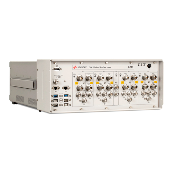
- Page 71 WLAN Mode Reference 1 About the Test Set The X-Series E6640A EXM Wireless Test Set is a one-box tester consisting of instruments loaded into a M9018A PXI mainframe with a front impact cover. The mainframe has a common PC controller (located on the far left) and M9300A PXI Frequency Reference (located in the center of the rack).
- Page 72 For the latest information on Keysight X-series measurement applications and upgrade kits, visit the following internet URL. http://www.keysight.com/find/e6640a Viewing a License Key Measurement applications that you purchased with your instrument have been installed and activated at the factory before shipment.
- Page 73 1 About the Test Set Installing Application Software any improvements and expanded functionality. Because the software was loaded at the initial purchase, further additional measurement applications may now be available. If the application you are interested in licensing is not available, you will need to do a software update.
- Page 74 View the Webpage, which you should click to display the home page). 3. Locate the Options & Accessories tab, as highlighted in the example below, which shows the home page for the E6640A. 4. Click the Options & Accessories tab, to display a list of available options and accessories for your instrument.
- Page 75 "Front and Rear Panel Features") of the document: Latest available on line document: E6640A Getting Started Guide Embedded PDF installed with the latest firmware revision: If you are viewing this information as a Help file in the instrument, then you can click on the link above to open the PDF document.
- Page 76 Display Annotations are fully detailed under the chapter "Front and Rear Panel Features" of the document: Latest available on line document: E6640A Getting Started Guide Embedded PDF installed with the latest firmware revision: If you are viewing this information as a Help file in the instrument, then you can click on the links above to open the PDF document.
- Page 77 "Front and Rear Panel Features") of the document: Latest available on line document: E6640A Getting Started Guide Embedded PDF installed with the latest firmware revision: If you are viewing this information as a Help file in the instrument, then you can click on the link above to open the PDF document.
- Page 78 1 About the Test Set Window Control Keys Window Control Keys The instrument provides three virtual-front-panel keys or four menu items for controlling windows. Virtual Front Panel The virtual-front-panel keys are Multi Window, Zoom, and Next Window. These are all “immediate action” keys.
- Page 79 1 About the Test Set Window Control Keys Multi-Window The Multi Window front-panel key will toggle you back and forth between the Normal View and the last Multi Window View (Zone Span, Trace Zoom or Spectrogram) that you were in, when using the Swept SA measurement of the Spectrum Analyzer Mode. ...
- Page 80 1 About the Test Set Window Control Keys RTSA measurements: Only two windows are available in the Spectrogram view under the Spectrum measurement and up to three windows are available in the Power vs. Time measurement, depending on the view set up. Remote Command :DISPlay:WINDow[:SELect] <number>...
- Page 81 1 About the Test Set Mouse and Keyboard Control Mouse and Keyboard Control If you do not have access to the instrument front-panel, there are several ways that a mouse and PC Keyboard can give you access to functions normally accessed using the front-panel keys. For instrument lacking a physical front panel display, you can watch the instrument display via external monitor or remote desktop connection Right-Click...
- Page 82 1 About the Test Set Mouse and Keyboard Control This method can be used to access any of the front-panel keys by using a mouse; as for example if you are accessing the instrument through Remote Desktop. The array of keys thus available is shown below: WLAN Mode Reference...
- Page 83 1 About the Test Set Mouse and Keyboard Control PC Keyboard If you have a PC keyboard plugged in (or via Remote Desktop), certain key codes on the PC keyboard map to front-panel keys on the GPSA front panel. These key codes are shown below: Front-panel key Key code Frequency...
- Page 84 1 About the Test Set Mouse and Keyboard Control Front-panel key Key code Full Screen CTRL+SHIFT+B Return CTRL+SHIFT+R Mute Mute Inc Audio Volume Up Dec Audio Volume Down Help Control CTRL Enter Return Cancel Delete Backspace Backspace Select Space Up Arrow Down Arrow Down Left Arrow...
- Page 85 1 About the Test Set Mouse and Keyboard Control This is a pictorial view of the table: WLAN Mode Reference...
- Page 86 1 About the Test Set Instrument Security & Memory Volatility Instrument Security & Memory Volatility If you are using the instrument in a secure environment, you may need details of how to clear or sanitize its memory, in compliance with published security standards of the United States Department of Defense, or other similar authorities.
- Page 87 (Undefined variable: Primary.ProductName) WLAN Mode Reference 2 About the WLAN Measurement Application This chapter describes WLAN measurements made by the test set.
- Page 88 2 About the WLAN Measurement Application What Does the Keysight V9077B WLAN Measurement Application Do? What Does the Keysight V9077B WLAN Measurement Application Do? The Keysight V9077B WLAN measurement application can be used to quickly ensure a product development conforms to regulatory requirements, as well as providing RF diagnostic and troubleshooting capability for a WLAN device.
- Page 89 (Undefined variable: Primary.ProductName) WLAN Mode Reference 3 Programming the Test Set This section provides introductory information about the programming documentation included with your product. "What Programming Information is Available?" on page 90 "STATus Subsystem " on page 123 "Common Commands" on page 163...
- Page 90 3 Programming the Test Set What Programming Information is Available? What Programming Information is Available? The X-Series Documentation can be accessed through the Additional Documentation page in the instrument Help system. It can also be found online at: http://www.keysight.com/find/exm. The following resources are available to help you create programs for automating your X-Series measurements: Resource Description...
- Page 91 3 Programming the Test Set List of SCPI Commands List of SCPI Commands *CAL? *CLS *ESE <integer> *ESE? *ESR? *IDN? *OPC *OPC? *OPT? *RCL <register#> *RST *SAV <register#> *SRE <integer> *SRE? *STB? *TRG *TST? *WAI ABORt CALCualte:EVM:SPECtrum? CALCualte:FLATness:SPECtrum? CALCulate:CHPower:LIMit:POWer <ampl> CALCulate:CHPower:LIMit:POWer? CALCulate:CHPower:LIMit:POWer:FAIL? CALCulate:CHPower:LIMit:POWer:STATe OFF | ON | 0 | 1...
- Page 92 3 Programming the Test Set List of SCPI Commands CALCulate:DATA[1]|2|...|6:PEAKs? <threshold>, <excursion>[, AMPLitude | FREQuency | TIME] CALCulate:DATA[1]|2|...|6:PEAKs? <threshold>, <excursion>[, AMPLitude | FREQuency | TIME[, ALL | GTDLine | LTDLine]] CALCulate:EVM:EQUalizer:TMODe SEQuence | SDATa CALCulate:EVM:EQUalizer:TMODe? CALCulate:EVM:IQEStimation OFF | ON | 0 | 1 CALCulate:EVM:IQEStimation? CALCulate:EVM:IQNorm OFF | ON | 0 | 1 CALCulate:EVM:IQNorm?
- Page 93 3 Programming the Test Set List of SCPI Commands CALCulate:EVM:LIMit:RMS:QA16:R3B4? CALCulate:EVM:LIMit:RMS:QA64:R2B3? CALCulate:EVM:LIMit:RMS:QPSK:R3B4 CALCulate:EVM:LIMit:RMS:QPSK:R1B2 <rel_ampl> CALCulate:EVM:LIMit:RMS:QPSK:R3B4 <rel_ampl> CALCulate:EVM:LIMit:RMS:QPSK:R1B2 CALCulate:EVM:MARKer:AOFF CALCulate:EVM:MARKer:COUPle[:STATe] ON | OFF | 1 | 0 CALCulate:EVM:MARKer:COUPle[:STATe]? CALCulate:EVM:MARKer[1]|2|...12:MAXimum CALCulate:EVM:MARKer[1]|2|...12:MAXimum:LEFT CALCulate:EVM:MARKer[1]|2|...12:MAXimum:NEXT CALCulate:EVM:MARKer[1]|2|...12:MAXimum:RIGHt CALCulate:EVM:MARKer[1]|2|...12:MINimum CALCulate:EVM:MARKer[1]|2|...|12:MODE POSition | DELTa | OFF CALCulate:EVM:MARKer[1]|2|...|12:MODE? CALCulate:EVM:MARKer[1]|2|...12:PTPeak CALCulate:EVM:MARKer[1]|2|...|12:REFerence <integer>...
- Page 94 3 Programming the Test Set List of SCPI Commands CALCulate:EVM:SUBCarrier:COUNt CALCulate:EVM:TRACk:PHASe OFF | ON | 0 | 1 CALCulate:EVM:TRACk:PHASe? CALCulate:FLATness:LIMit:LOWer:SECTion1 <rel_amp> CALCulate:FLATness:LIMit:LOWer:SECTion2 <rel_amp> CALCulate:FLATness:LIMit:LOWer:SECTion2? CALCulate:FLATness:LIMit:LOWer:SECTion1? CALCulate:FLATness:LIMit:UPPer:SECTion2 <rel_amp> CALCulate:FLATness:LIMit:UPPer:SECTion1 <rel_amp> CALCulate:FLATness:LIMit:UPPer:SECTion1? CALCulate:FLATness:LIMit:UPPer:SECTion2? CALCulate:FLATness:MARKer:AOFF CALCulate:FLATness:MARKer:COUPle[:STATe] ON | OFF | 1 | 0 CALCulate:FLATness:MARKer:COUPle[:STATe]? CALCulate:FLATness:MARKer[1]|2|...12:MAXimum CALCulate:FLATness:MARKer[1]|2|...12:MODE POSition | DELTa | OFF...
- Page 95 3 Programming the Test Set List of SCPI Commands CALCulate:OBWidth:MARKer[1]|2|...|12:REFerence <integer> CALCulate:OBWidth:MARKer[1]|2|...|12:REFerence? CALCulate:OBWidth:MARKer[1]|2|...|12:STATe OFF | ON | 0 | 1 CALCulate:OBWidth:MARKer[1]|2|...|12:STATe? CALCulate:OBWidth:MARKer[1]|2|...|12:X <freq> CALCulate:OBWidth:MARKer[1]|2|...|12:X? CALCulate:OBWidth:MARKer[1]|2|...|12:X:POSition <real> CALCulate:OBWidth:MARKer[1]|2|...|12:X:POSition? CALCulate:OBWidth:MARKer[1]|2|...|12:Y? CALCulate:PVTime:FAIL UP | DOWN | BOTH CALCulate:PVTime:FAIL? CALCulate:PVTime:LIMit:DRTime CALCulate:PVTime:LIMit:RDTime <time> CALCulate:PVTime:LIMit:RDTime? CALCulate:PVTime:LIMit:RUTime <time> CALCulate:PVTime:LIMit:RUTime? CALCulate:PVTime:LIMit:URTime CALCulate:PVTime:MARKer:AOFF...
- Page 96 3 Programming the Test Set List of SCPI Commands CALCulate:WAVeform:MARKer[1]|2|...|12:MAXimum:NEXT CALCulate:WAVeform:MARKer[1]|2|...|12:MINimum CALCulate:WAVeform:MARKer[1]|2|...|12:MODE POSition | DELTa | OFF CALCulate:WAVeform:MARKer[1]|2|...|12:MODE? CALCulate:WAVeform:MARKer[1]|2|...|12:REFerence <integer> CALCulate:WAVeform:MARKer[1]|2|...|12:REFerence? CALCulate:WAVeform:MARKer[1]|2|...|12:TRACe RFENvelope | I | Q | IQ CALCulate:WAVeform:MARKer[1]|2|...|12:TRACe? CALCulate:WAVeform:MARKer[1]|2|...|12:X <time> CALCulate:WAVeform:MARKer[1]|2|...|12:X? CALCulate:WAVeform:MARKer[1]|2|...|12:X:POSition <real> CALCulate:WAVeform:MARKer[1]|2|...|12:X:POSition? CALCulate:WAVeform:MARKer[1]|2|...|4:X:SPAN CALCulate:WAVeform:MARKer[1]|2|...|12:Y? CALibration[:ALL] CALibration[:ALL]? CALibration[:ALL]:NPENding CALibration:EXPired? CALibration:IF...
- Page 97 3 Programming the Test Set List of SCPI Commands CONFigure:PVTime CONFigure:PVTime:NDEFault CONFigure:SEMask CONFigure:SEMask CONFigure:SEMask:NDEFault CONFigure:SPECtrum CONFigure:SPECtrum:NDEFault CONFigure:WAVeform CONFigure:WAVeform CONFigure:WAVeform:NDEFault COUPle ALL | NONE DISPlay:<measurement>:ANNotation:TITLe:DATA <string> DISPlay:<measurement>:ANNotation:TITLe:DATA? DISPlay:ACTivefunc[:STATe] ON | OFF | 1 | 0 DISPlay:ACTivefunc[:STATe]? DISPlay:ANNotation:MBAR[:STATe] OFF | ON | 0 | 1 DISPlay:ANNotation:MBAR[:STATe]? DISPlay:ANNotation:SCReen[:STATe] OFF | ON | 0 | 1 DISPlay:ANNotation:SCReen[:STATe]?
- Page 98 3 Programming the Test Set List of SCPI Commands DISPlay:EVM:VIEW[1]:WINDow[1]:TRACe:ROTation:STATe 0 | 1 | OFF | ON DISPlay:EVM:VIEW[1]:WINDow1:TRACe:ROTation:STATe? DISPlay:FLATness:LLINe ON | OFF | 1 | 0 DISPlay:FLATness:LLINe? DISPlay:FLATness:VIEW[1]:WINDow[1]:TRACe:X[:SCALe]:COUPle 0 | 1 | OFF | ON DISPlay:FLATness:VIEW[1]:WINDow[1]:TRACe:X[:SCALe]:COUPle? DISPlay:FLATness:VIEW[1]:WINDow[1]:TRACe:X[:SCALe]:PDIVision <real> DISPlay:FLATness:VIEW[1]:WINDow[1]:TRACe:X[:SCALe]:PDIVision? DISPlay:FLATness:VIEW[1]:WINDow[1]:TRACe:X[:SCALe]:RLEVel <real> DISPlay:FLATness:VIEW[1]:WINDow[1]:TRACe:X[:SCALe]:RLEVel? DISPlay:FLATness:VIEW[1]:WINDow[1]:TRACe:X[:SCALe]:RPOSition LEFT | CENTer | RIGHt...
- Page 99 3 Programming the Test Set List of SCPI Commands DISPlay:PVTime:VIEW[1]:WINDow[1]:TRACe:Y[:SCALe]:COUPle 0 | 1 | OFF | ON DISPlay:PVTime:VIEW[1]:WINDow[1]:TRACe:Y[:SCALe]:COUPle? DISPlay:PVTime:VIEW[1]:WINDow[1]:TRACe:Y[:SCALe]:PDIVision <rel_ampl> DISPlay:PVTime:VIEW[1]:WINDow[1]:TRACe:Y[:SCALe]:PDIVision? DISPlay:PVTime:VIEW[1]:WINDow[1]:TRACe:Y[:SCALe]:RLEVel <real> DISPlay:PVTime:VIEW[1]:WINDow[1]:TRACe:Y[:SCALe]:RLEVel? DISPlay:PVTime:VIEW[1]:WINDow[1]:TRACe:Y[:SCALe]:RPOSition TOP | CENTer | BOTTom DISPlay:PVTime:VIEW[1]:WINDow[1]:TRACe:Y[:SCALe]:RPOSition? DISPlay:SEMask:VIEW:NSELect <integer> DISPlay:SEMask:VIEW:NSELect? DISPlay:SEMask:VIEW[:SELect] APFReq | RPFReq | IPOWer | CINFormation DISPlay:SEMask:VIEW[:SELect]? DISPlay:SEMask:VIEW[1]:WINDow[1]:TRACe:X[:SCALe]:COUPle 0 | 1 | OFF | ON DISPlay:SEMask:VIEW[1]:WINDow[1]:TRACe:X[:SCALe]:COUPle?
- Page 100 3 Programming the Test Set List of SCPI Commands DISPlay:WAVeform:VIEW2:WINDow[1]:TRACe:Y[:SCALe]:RLEVel <voltage> DISPlay:WAVeform:VIEW[1]:WINDow[1]:TRACe:Y[:SCALe]:RLEVel <ampl> DISPlay:WAVeform:VIEW2:WINDow[1]:TRACe:Y[:SCALe]:RLEVel? DISPlay:WAVeform:VIEW[1]:WINDow[1]:TRACe:Y[:SCALe]:RLEVel? DISPlay:WAVeform:VIEW[1]:WINDow[1]:TRACe:Y[:SCALe]:RPOSition TOP | CENTer | BOTTom DISPlay:WAVeform:VIEW2:WINDow[1]:TRACe:Y[:SCALe]:RPOSition TOP | CENTer | BOTTom DISPlay:WAVeform:VIEW[1]:WINDow[1]:TRACe:Y[:SCALe]:RPOSition? DISPlay:WAVeform:VIEW2:WINDow[1]:TRACe:Y[:SCALe]:RPOSition? DISPlay:WINDow[1]:ANNotation[:ALL] OFF | ON | 0 | 1 DISPlay:WINDow[1]:ANNotation[:ALL]? DISPlay:WINDow:FORMat:TILE DISPlay:WINDow:FORMat:ZOOM DISPlay:WINDow[:SELect] <number>...
- Page 101 3 Programming the Test Set List of SCPI Commands INITiate:SPECtrum INITiate:WAVeform INPut<1|2>:TYPE INPUT1 | INPUT2 INPut<1|2>:TYPE? INPut[1]|2:LISN:FILTer:HPAS[:STATe] ON | OFF INPut[1]|2:LISN:FILTer:HPAS[:STATe]? INPut[1]|2:LISN:PEARth GROunded | FLOating INPut[1]|2:LISN:PEARth? INPut[1]|2:LISN:PHASe L1 | L2 | L3 | N INPut[1]|2:LISN:PHASe? INPut[1]|2:LISN[:TYPE] FOURphase | ESH2Z5 | ENV216 | OFF INPut[1]|2:LISN[:TYPE]? INPut:MIXer EXTernal | INTernal INPut:MIXer?
- Page 102 3 Programming the Test Set List of SCPI Commands MMEMory:CDIRectory? MMEMory:COPY <string>, <string>[, <string>, <string>] MMEMory:COPY:DEVice <source_string>, <dest_string> MMEMory:DATA <file_name>, <data> MMEMory:DATA? <file_name> MMEMory:DELete <file_name>[, <directory_name>] MMEMory:HEADer:ID? "<filename>" MMEMory:LOAD:MASK <string> MMEMory:LOAD:SEQuences:| SLISt | ALISt | SAAList | "MySequence.txt" MMEMory:LOAD:STATe 1, <filename> MMEMory:LOAD:STATe <filename>...
- Page 103 3 Programming the Test Set List of SCPI Commands [:SENSe]:CHPower:BANDwidth:INTegration? [:SENSe]:CHPower:BANDwidth[:RESolution] <bandwidth> [:SENSe]:CHPower:BANDwidth[:RESolution]? [:SENSe]:CHPower:BANDwidth[:RESolution]:AUTO ON | OFF | 1 | 0 [:SENSe]:CHPower:BANDwidth[:RESolution]:AUTO? [:SENSe]:CHPower:BANDwidth:SHAPe GAUSsian | FLATtop [:SENSe]:CHPower:BANDwidth:SHAPe? [:SENSe]:CHPower:BANDwidth:VIDeo <bandwidth> [:SENSe]:CHPower:BANDwidth:VIDeo? [:SENSe]:CHPower:BANDwidth:VIDeo:AUTO ON | OFF | 1 | 0 [:SENSe]:CHPower:BANDwidth:VIDeo:AUTO? [:SENSe]:CHPower:BWIDth[:RESolution] [:SENSe]:CHPower:BWIDth:SHAPe [:SENSe]:CHPower:DETector:AUTO ON | OFF | 1 | 0 [:SENSe]:CHPower:DETector:AUTO?
- Page 104 3 Programming the Test Set List of SCPI Commands [:SENSe]:CORRection:CSET[1]|2|...|8:DESCription "text" [:SENSe]:CORRection:CSET[1]|2|...|8:DESCription? [:SENSe]:CORRection:CSET[1]|2|...|8:RF:PORT RFIN | RFIO1 | RFIO2 | RFOut | GPSout | GNSSout | RFIO3 | RFIO4 [:SENSe]:CORRection:CSET[1]|2|...|8:RF:PORT? [:SENSe]:CORRection:CSET[1]|2|...|8:RF:PORT:RFIO2 SOURce | ANALyzer | BOTH [:SENSe]:CORRection:CSET[1]|2|...|8:RF:PORT:RFIO1 SOURce | ANALyzer | BOTH [:SENSe]:CORRection:CSET[1]|2|...|8:RF:PORT:RFIO1? [:SENSe]:CORRection:CSET[1]|2|...|8:RF:PORT:RFIO2? [:SENSe]:CORRection:CSET[1]|2|...|8[:STATe] ON | OFF | 1 | 0...
- Page 105 3 Programming the Test Set List of SCPI Commands [:SENSe]:DEMod[:WLAN]:AC160:SUBCarrier:SPACing <freq> [:SENSe]:DEMod[:WLAN]:AC20:SUBCarrier:SPACing <freq> [:SENSe]:DEMod[:WLAN]:AC80:SUBCarrier:SPACing? [:SENSe]:DEMod[:WLAN]:AC160:SUBCarrier:SPACing? [:SENSe]:DEMod[:WLAN]:AC40:SUBCarrier:SPACing? [:SENSe]:DEMod[:WLAN]:AC20:SUBCarrier:SPACing? [:SENSe]:DEMod[:WLAN]:ACT80:FORMat AUTO | BPSK | QPSK | QAM16 | QAM64 | QAM256 | SIG [:SENSe]:DEMod[:WLAN]:ACT80:FORMat? [:SENSe]:DEMod[:WLAN]:ACT80:GINTerval R1B4 | R1B8 | SIG | OTHer [:SENSe]:DEMod[:WLAN]:ACT80:GINTerval? [:SENSe]:DEMod[:WLAN]:ACT80:GINTerval:LENGth <real>...
- Page 106 3 Programming the Test Set List of SCPI Commands [:SENSe]:EBWidth:XDB [:SENSe]:EVM:AVERage:COUNt <integer> [:SENSe]:EVM:AVERage:COUNt? [:SENSe]:EVM:AVERage[:STATe] OFF | ON | 0 | 1 [:SENSe]:EVM:AVERage[:STATe]? [:SENSe]:EVM:AVERage:TCONtrol EXPonential | REPeat [:SENSe]:EVM:AVERage:TCONtrol? [:SENSe]:EVM:BANDwidth[:RESolution] <bandwidth> [:SENSe]:EVM:BANDwidth[:RESolution]? [:SENSe]:EVM:CADJust <real> [:SENSe]:EVM:CADJust? [:SENSe]:EVM:CHPRate <frequency> [:SENSe]:EVM:CHPRate? [:SENSe]:EVM:COMPensate OFF | ON | 0 | 1 [:SENSe]:EVM:COMPensate? [:SENSe]:EVM:CRATe <frequency>...
- Page 107 3 Programming the Test Set List of SCPI Commands [:SENSe]:EVM:TIME:RESMax? [:SENSe]:EVM:TIME:RESult:LENGth <integer> [:SENSe]:EVM:TIME:RESult:LENGth? [:SENSe]:EVM:TIME:RESult:MAX <integer> [:SENSe]:EVM:TIME:RESult:MAX? [:SENSe]:EVM:TIME:RESult:SIG OFF | ON | 0 | 1 [:SENSe]:EVM:TIME:RESult:SIG? [:SENSe]:EVM:TIME:RESult[:STATe]:AUTO OFF | ON | 0 | 1 [:SENSe]:EVM:TIME:RESult[:STATe]:AUTO? [:SENSe]:EVM:TIME:SEARchlength <real> [:SENSe]:EVM:TIME:SEARchlength [:SENSe]:EVM:TIME:SEARchlength? [:SENSe]:EVM:TIME:SLENgth <time> [:SENSe]:EVM:TIME:SLENgth? [:SENSe]:EVM:TRACk:AMP OFF | ON | 0 | 1 [:SENSe]:EVM:TRACk:AMP?
- Page 108 3 Programming the Test Set List of SCPI Commands [:SENSe]:FLATness:TADJust? [:SENSe]:FLATness:TIMadj <percent> [:SENSe]:FLATness:TIME:SEARchlen <time> [:SENSe]:FREQuency:CENTer <freq> [:SENSe]:FREQuency:CENTer? [:SENSe]:FREQuency:CENTer:STEP:AUTO OFF | ON | 0 | 1 [:SENSe]:FREQuency:CENTer:STEP:AUTO? [:SENSe]:FREQuency:CENTer:STEP[:INCRement] <freq> [:SENSe]:FREQuency:CENTer:STEP[:INCRement]? [:SENSe]:FREQuency:EMIXer:CENTer <freq> [:SENSe]:FREQuency:EMIXer:CENTer? [:SENSe]:FREQuency:IQ:CENTer <freq> [:SENSe]:FREQuency:IQ:CENTer? [:SENSe]:FREQuency:RF:CENTer <freq> [:SENSe]:FREQuency:RF:CENTer? [:SENSe]:HDUPlex:PORT:INPut RFIO3 | RFIO4 [:SENSe]:HDUPlex:PORT:OUTPut RFIO3 | RFIO4 [:SENSe]:OBWidth:AVERage:COUNt <integer>...
- Page 109 3 Programming the Test Set List of SCPI Commands [:SENSe]:OBWidth:SWEep:TIME <time> [:SENSe]:OBWidth:SWEep:TIME? [:SENSe]:OBWidth:SWEep:TIME:AUTO OFF | ON | 0 | 1 [:SENSe]:OBWidth:SWEep:TIME:AUTO? [:SENSe]:OBWidth:SWEep:TIME:AUTO:RULes NORMal | ACCuracy [:SENSe]:OBWidth:SWEep:TIME:AUTO:RULes? [:SENSe]:OBWidth:XDB <rel_ampl> [:SENSe]:OBWidth:XDB? [:SENSe]:POWer[:RF]:RANGe <real> [:SENSe]:POWer[:RF]:RANGe? [:SENSe]:POWer[:RF]:RANGe:MIXer:OFFSet <real> [:SENSe]:POWer[:RF]:RANGe:MIXer:OFFSet? [:SENSe]:POWer[:RF]:RANGe:OPTimize IMMediate [:SENSe]:POWer[:RF]:RANGe:OPTimize:ATTenuation OFF | ON | ELECtrical | COMBined [:SENSe]:POWer[:RF]:RANGe:OPTimize:ATTenuation? [:SENSe]:POWer[:RF]:RANGe:PARatio <real>...
- Page 110 3 Programming the Test Set List of SCPI Commands [:SENSe]:ROSCillator:EXTernal:FREQuency <freq> [:SENSe]:ROSCillator:EXTernal:FREQuency? [:SENSe]:ROSCillator:SOURce INTernal | EXTernal [:SENSe]:ROSCillator:SOURce? [:SENSe]:ROSCillator:SOURce:TYPE INTernal | EXTernal | SENSe | PULSe [:SENSe]:ROSCillator:SOURce:TYPE? [:SENSe]:SEMask:AVERage:COUNt <integer> [:SENSe]:SEMask:AVERage:COUNt? [:SENSe]:SEMask:AVERage[:STATe] ON | OFF | 1 | 0 [:SENSe]:SEMask:AVERage[:STATe]? [:SENSe]:SEMask:BANDwidth[1]|2:INTegration <bandwidth> [:SENSe]:SEMask:BANDwidth[1]|2:INTegration? [:SENSe]:SEMask:BANDwidth[1]|2[:RESolution] <bandwidth>...
- Page 111 3 Programming the Test Set List of SCPI Commands [:SENSe]:SEMask:LIMits STD | MAN [:SENSe]:SEMask:LIMits? [:SENSe]:SEMask:OFFSet[1]|2:LIST:BWIDth:IMULti [:SENSe]:SEMask:OFFSet[1]|2:LIST:BWIDth[:RESolution] [:SENSe]:SEMask:OFFSet[1]|2:LIST:BWIDth:VIDeo [:SENSe]:SEMask:OFFSet[1]|2:LIST:SWEep[:TIME] [:SENSe]:SEMask:OFFSet[1]|2[:OUTer]:LIST:BANDwidth:IMULti <integer>, ... [:SENSe]:SEMask:OFFSet[1]|2[:OUTer]:LIST:BANDwidth:IMULti? [:SENSe]:SEMask:OFFSet[1]|2[:OUTer]:LIST:BANDwidth[:RESolution] <bandwidth>, ... [:SENSe]:SEMask:OFFSet[1]|2[:OUTer]:LIST:BANDwidth[:RESolution]? [:SENSe]:SEMask:OFFSet[1]|2[:OUTer]:LIST:BANDwidth[:RESolution]:AUTO OFF | ON | 1 | 0, ... [:SENSe]:SEMask:OFFSet[1]|2[:OUTer]:LIST:BANDwidth[:RESolution]:AUTO? [:SENSe]:SEMask:OFFSet[1]|2[:OUTer]:LIST:BANDwidth:VIDeo <freq>, ... [:SENSe]:SEMask:OFFSet[1]|2[:OUTer]:LIST:BANDwidth:VIDeo? [:SENSe]:SEMask:OFFSet[1]|2[:OUTer]:LIST:BANDwidth:VIDeo:AUTO OFF | ON | 0 | 1, ...
- Page 112 3 Programming the Test Set List of SCPI Commands [:SENSe]:SEMask:OFFSet[1]|2[:OUTer]:LIST:TEST ABSolute | AND | OR | RELative, ... [:SENSe]:SEMask:OFFSet[1]|2[:OUTer]:LIST:TEST? [:SENSe]:SEMask:OFFSet[1]|2:TYPE CTOCenter | CTOEdge | ETOCenter | ETOEdge [:SENSe]:SEMask:OFFSet[1]|2:TYPE? [:SENSe]:SEMask:SWEep[1]|2:TIME <time> [:SENSe]:SEMask:SWEep[1]|2:TIME? [:SENSe]:SEMask:SWEep[1]|2:TIME:AUTO OFF | 0 | ON | 1 [:SENSe]:SEMask:SWEep[1]|2:TIME:AUTO? [:SENSe]:SEMask:T80Mask:AUTO ON | OFF | 1 | 0[:SENSe]:SEMask:T80Mask:AUTO? [:SENSe]:SEMask:TYPE PSDRef | TPRef | SPRef [:SENSe]:SEMask:TYPE?
- Page 113 3 Programming the Test Set List of SCPI Commands [:SENSe]:WAVeform:DIF:FILTer:BANDwidth:AUTO? [:SENSe]:WAVeform:DIF:FILTer:TYPE GAUSsian | FLATtop | SNYQuist | RSNYquist | RCOSine | RRCosine [:SENSe]:WAVeform:DIF:FILTer:TYPE GAUSsian | FLATtop [:SENSe]:WAVeform:DIF:FILTer:TYPE? [:SENSe]:WAVeform:DIF:FILTer:TYPE? [:SENSe]:WAVeform:SRATe <freq> [:SENSe]:WAVeform:SRATe? [:SENSe]:WAVeform:SWEep:TIME <time> [:SENSe]:WAVeform:SWEep:TIME? [:SENSe]:WAVeform:WBIF:FILTer:ALPHa SOURce:AM[:DEPTh][:LINear] SOURce:AM[:DEPTh][:LINear]? SOURce:AM:INTernal:FREQuency SOURce:AM:INTernal:FREQuency? SOURce:AM:STATe SOURce:AM:STATe? SOURce:FM[:DEViation] SOURce:FM[:DEViation]?
- Page 114 3 Programming the Test Set List of SCPI Commands SOURce:LIST:SETup:CNFRequency <double>, <double>, <double>, ... SOURce:LIST:SETup:CNFRequency? SOURce:LIST:SETup:DURation:TYPE <enum>, <enum>, <enum>, ... SOURce:LIST:SETup:DURation:TYPE? SOURce:LIST:SETup:INPut:TRIGger <enum>, <enum>, <enum>, ... SOURce:LIST:SETup:INPut:TRIGger? SOURce:LIST:SETup:OUTPut:TRIGger ? SOURce:LIST:SETup:OUTPut:TRIGger <bool>, <bool>, <bool>, ... SOURce:LIST:SETup:RADio:BAND <enum>, <enum>, <enum>, ... SOURce:LIST:SETup:RADio:BAND? SOURce:LIST:SETup:RADio:BAND:LINK <enum>, <enum>, <enum>, ...
- Page 115 3 Programming the Test Set List of SCPI Commands | BANDII | BANDIII | BANDIV | BANDV | BANDVI | BANDVII | BANDVIII | BANDIX | BANDX | BANDXI | BANDXII | BANDXIII | BANDXIV | BANDXIX | USCELL | USPCS | JAPAN | KOREAN | NMT | IMT2K | UPPER | SECOND | PAMR400 | PAMR800 | IMTEXT | PCS1DOT9G | AWS | US2DOT5G | PUBLIC | LOWER | NONE | BAND1 | BAND2 | BAND3 | BAND4 | BAND5 | BAND6 | BAND7 | BAND8 | BAND10 | BAND11 |...
- Page 116 3 Programming the Test Set List of SCPI Commands SOURce:RADio:ARB:MPOLarity:MARKer4 POSitive | NEGative SOURce:RADio:ARB:MPOLarity:MARKer3 POSitive | NEGative SOURce:RADio:ARB:MPOLarity:MARKer1 POSitive | NEGative SOURce:RADio:ARB:MPOLarity:MARKer2 POSitive | NEGative SOURce:RADio:ARB:MPOLarity:MARKer1? SOURce:RADio:ARB:MPOLarity:MARKer3? SOURce:RADio:ARB:MPOLarity:MARKer2? SOURce:RADio:ARB:MPOLarity:MARKer4? SOURce:RADio:ARB:RETRigger ON | OFF | IMMediate SOURce:RADio:ARB:RETRigger? SOURce:RADio:ARB:RSCaling <real> SOURce:RADio:ARB:RSCaling? SOURce:RADio:ARB:SCLock:RATE <freq> SOURce:RADio:ARB:SCLock:RATE? SOURce:RADio:ARB:SEQuence[:MWAVeform] <filename>, <waveform1>, <reps>, NONE | M1 | M2 | M3 | M4 | M1M2 | M1M3 | M1M4 | M2M3 | M2M4 | M3M4 |...
- Page 117 3 Programming the Test Set List of SCPI Commands STATus:QUEStionable:CALibration:EXTended:FAILure:ENABle? STATus:QUEStionable:CALibration:EXTended:FAILure[:EVENt]? STATus:QUEStionable:CALibration:EXTended:FAILure:NTRansition <integer> STATus:QUEStionable:CALibration:EXTended:FAILure:NTRansition? STATus:QUEStionable:CALibration:EXTended:FAILure:PTRansition <integer> STATus:QUEStionable:CALibration:EXTended:FAILure:PTRansition? STATus:QUEStionable:CALibration:EXTended:NEEDed:CONDition? STATus:QUEStionable:CALibration:EXTended:NEEDed:ENABle <integer> STATus:QUEStionable:CALibration:EXTended:NEEDed:ENABle? STATus:QUEStionable:CALibration:EXTended:NEEDed[:EVENt]? STATus:QUEStionable:CALibration:EXTended:NEEDed:NTRansition <integer> STATus:QUEStionable:CALibration:EXTended:NEEDed:NTRansition? STATus:QUEStionable:CALibration:EXTended:NEEDed:PTRansition <integer> STATus:QUEStionable:CALibration:EXTended:NEEDed:PTRansition? STATus:QUEStionable:CALibration:NTRansition <integer> STATus:QUEStionable:CALibration:NTRansition? STATus:QUEStionable:CALibration:PTRansition <integer> STATus:QUEStionable:CALibration:PTRansition? STATus:QUEStionable:CALibration:SKIPped:CONDition? STATus:QUEStionable:CALibration:SKIPped:ENABle <integer> STATus:QUEStionable:CALibration:SKIPped:ENABle? STATus:QUEStionable:CALibration:SKIPped[:EVENt]? STATus:QUEStionable:CALibration:SKIPped:NTRansition <integer> STATus:QUEStionable:CALibration:SKIPped:NTRansition? STATus:QUEStionable:CALibration:SKIPped:PTRansition <integer>...
- Page 118 3 Programming the Test Set List of SCPI Commands STATus:QUEStionable:INTegrity:SIGNal:PTRansition? STATus:QUEStionable:INTegrity:UNCalibrated:CONDition? STATus:QUEStionable:INTegrity:UNCalibrated:ENABle STATus:QUEStionable:INTegrity:UNCalibrated:ENABle? STATus:QUEStionable:INTegrity:UNCalibrated[:EVENt]? STATus:QUEStionable:INTegrity:UNCalibrated:NTRansition <integer> STATus:QUEStionable:INTegrity:UNCalibrated:NTRansition? STATus:QUEStionable:INTegrity:UNCalibrated:PTRansition <integer> STATus:QUEStionable:INTegrity:UNCalibrated:PTRansition? STATus:QUEStionable:NTRansition <integer> STATus:QUEStionable:NTRansition? STATus:QUEStionable:POWer:CONDition? STATus:QUEStionable:POWer:ENABle <integer> STATus:QUEStionable:POWer:ENABle? STATus:QUEStionable:POWer[:EVENt]? STATus:QUEStionable:POWer:NTRansition <integer> STATus:QUEStionable:POWer:NTRansition? STATus:QUEStionable:POWer:PTRansition <integer> STATus:QUEStionable:POWer:PTRansition?> STATus:QUEStionable:PTRansition <integer> STATus:QUEStionable:PTRansition? STATus:QUEStionable:TEMPerature:CONDition? STATus:QUEStionable:TEMPerature:ENABle <integer> STATus:QUEStionable:TEMPerature:ENABle? STATus:QUEStionable:TEMPerature[:EVENt]? STATus:QUEStionable:TEMPerature:NTRansition <integer>...
- Page 119 3 Programming the Test Set List of SCPI Commands SYSTem:CSYStem? SYSTem:DATE "<year>, <month>, <day>" SYSTem:DATE? SYSTem:DEFault [ALL] | ALIGn | INPut | MISC | MODes | PON SYSTem:ERRor[:NEXT]? SYSTem:ERRor:OVERload[:STATe] 0 | 1 | OFF | ON SYSTem:ERRor:PUP? SYSTem:ERRor:VERBose OFF | ON | 0 | 1 SYSTem:ERRor:VERBose? SYSTem:HELP:HEADers? SYSTem:HID?
- Page 120 3 Programming the Test Set List of SCPI Commands SYSTem:PON:APPLication:VMEMory:USED? SYSTem:PON:APPLication:VMEMory:USED:NAME? <INSTrument:SELectname> SYSTem:PON:MODE SA | BASIC | ADEMOD | NFIGURE | PNOISE | CDMA2K | TDSCDMA | VSA | VSA89601 | WCDMA | WIMAXOFDMA SYSTem:PON:MODE? SYSTem:PON:TIME? SYSTem:PON:TYPE MODE | USER | LAST SYSTem:PON:TYPE PRESet SYSTem:PON:TYPE? SYSTem:PRESet...
- Page 121 3 Programming the Test Set List of SCPI Commands TRIGger[:SEQuence]:DELay:STATe OFF | ON | 0 | 1 TRIGger[:SEQuence]:DELay:STATe? TRIGger[:SEQuence]:EXTernal2:DELay <time> TRIGger[:SEQuence]:EXTernal:DELay TRIGger[:SEQuence]:EXTernal1:DELay <time> TRIGger[:SEQuence]:EXTernal2:DELay? TRIGger[:SEQuence]:EXTernal1:DELay? TRIGger[:SEQuence]:EXTernal1:DELay:COMPensation OFF | ON | 0 | 1 TRIGger[:SEQuence]:EXTernal2:DELay:COMPensation OFF | ON | 0 | 1 TRIGger[:SEQuence]:EXTernal2:DELay:COMPensation? TRIGger[:SEQuence]:EXTernal1:DELay:COMPensation? TRIGger[:SEQuence]:EXTernal1:DELay:STATe OFF | ON | 0 | 1...
- Page 122 3 Programming the Test Set List of SCPI Commands TRIGger[:SEQuence]:HOLDoff:TYPE? TRIGger[:SEQuence]:IF:LEVel TRIGger[:SEQuence]:IF:LEVel? TRIGger[:SEQuence]:IF:SLOPe NEGative | POSitive TRIGger[:SEQuence]:IF:SLOPe? TRIGger[:SEQuence]:OFFSet <time> TRIGger[:SEQuence]:OFFSet? TRIGger[:SEQuence]:OFFSet:STATe OFF | ON | 0 | 1 TRIGger[:SEQuence]:OFFSet:STATe? TRIGger[:SEQuence]:RFBurst:DELay <time> TRIGger[:SEQuence]:RFBurst:DELay? TRIGger[:SEQuence]:RFBurst:DELay:STATe OFF | ON | 0 | 1 TRIGger[:SEQuence]:RFBurst:DELay:STATe? TRIGger[:SEQuence]:RFBurst:LEVel TRIGger[:SEQuence]:RFBurst:LEVel:ABSolute <ampl>...
- Page 123 3 Programming the Test Set STATus Subsystem STATus Subsystem The following diagram shows the entire Status Register Subsystem implementation of the X Series instruments. Detailed Description The STATus subsystem remote commands set and query the status hardware registers. This system of registers monitors various events and conditions in the instrument.
- Page 124 3 Programming the Test Set STATus Subsystem The operation and questionable status registers are sets of registers that monitor the overall instrument condition. They are accessed with the STATus:OPERation and STATus:QUEStionable commands in the STATus command subsystem. Each register set is made up of five registers: •...
- Page 125 3 Programming the Test Set STATus Subsystem • *STB? (status byte) queries the value of the status byte register without erasing its contents. How to Use the Status Registers A program often needs to be able to detect and manage error conditions or changes in instrument status. There are two methods you can use to programmatically access the information in status registers: •...
- Page 126 3 Programming the Test Set STATus Subsystem event register is cleared. Querying the event register allows you to detect that this condition occurred even if the condition no longer exists. The event register can only be cleared by querying it or sending the *CLS command.
- Page 127 3 Programming the Test Set STATus Subsystem 2. It’s usually a good idea to start by clearing all the status registers with *CLS. 3. Sending the STAT:QUES:INT:ENAB 1024 command lets you monitor only bit 10 events, instead of the default monitoring all the bits in the register. The register default is for positive transition events (0 to 1 transition).
- Page 128 3 Programming the Test Set STATus Subsystem The SRQ process sets the SRQ true. It also sets the status byte’s request service (RQS) bit to 1. Both actions are necessary to inform the controller that the instrument requires service. Setting the SRQ line only informs the controller that some device on the bus requires service.
- Page 129 3 Programming the Test Set STATus Subsystem The Status Byte Register The RQS bit is read and reset by a serial poll. The same bit position (MSS) is read, non-destructively by the *STB? command. If you serial poll bit 6 it is read as RQS, but if you send *STB it reads bit 6 as MSS. For more information refer to IEEE 488.2 standards, section 11.
- Page 130 3 Programming the Test Set STATus Subsystem Description 0, 1 These bits are always set to 0. A 1 in this bit position indicates that the SCPI error queue is not empty which means that it contains at least one error message. A 1 in this bit position indicates that the data questionable summary bit has been set.
- Page 131 3 Programming the Test Set STATus Subsystem bit 6) to your numeric sum when you enable any bits for a service request. The command *SRE? returns the decimal value of the sum of the bits previously enabled with the *SRE <integer> command. The service request enable register presets to zeros (0).
- Page 132 3 Programming the Test Set STATus Subsystem Description A 1 in this bit position indicates that all pending operations were completed following execution of the *OPC command. This bit is for GPIB handshaking to request control. Currently it is set to 0 because there are no implementations where the spectrum analyzer controls another instrument.
- Page 133 3 Programming the Test Set STATus Subsystem byte register will be set to 1, send the command *ESE 192 (128 + 64). The command *ESE? returns the decimal value of the sum of the bits previously enabled with the *ESE <integer> command. The standard event status enable register presets to zeros (0).
- Page 134 3 Programming the Test Set STATus Subsystem Power summary The instrument hardware has detected a power unleveled condition. Temperature summary The instrument is still warming up. Frequency summary The instrument hardware has detected an unlocked condition or a problem with the external frequency reference. Calibration summary The instrument has detected a hardware problem while doing the automatic internal alignment process.
- Page 135 3 Programming the Test Set STATus Subsystem Operation Enable This command determines which bits in the Operation Event register, will set the Operation Status Summary bit (bit 7) in the Status Byte Register. The variable <integer> is the sum of the decimal values of the bits you want to enable.
- Page 136 3 Programming the Test Set STATus Subsystem Mode Remote Command :STATus:OPERation:NTRansition <integer> :STATus:OPERation:NTRansition? Example STAT:OPER:NTR 1 Align Now operation complete will be reported to the Status Byte Register. Preset 32767 Status Bits/OPC Sequential command dependencies Initial S/W Revision Prior to A.02.00 Operation Positive Transition This command determines which bits in the Operation Condition register will set the corresponding bit in the Operation Event register when the condition register bit has a positive transition (0 to 1).
- Page 137 3 Programming the Test Set STATus Subsystem Questionable Register "Questionable Condition " on page 137 "Questionable Enable " on page 137 "Questionable Event Query " on page 138 "Questionable Negative Transition " on page 138 "Questionable Positive Transition" on page 138 Questionable Condition This query returns the decimal value of the sum of the bits in the Questionable Condition register.
- Page 138 3 Programming the Test Set STATus Subsystem Questionable Event Query This query returns the decimal value of the sum of the bits in the Questionable Event register. The register requires that the associated PTR or NTR filters be set before a condition register bit can set a bit in the event register.
- Page 139 3 Programming the Test Set STATus Subsystem Remote Command :STATus:QUEStionable:PTRansition <integer> :STATus:QUEStionable:PTRansition? Example STAT:QUES:PTR 16 Temperature summary ‘questionable asserted’ will be reported to the Status Byte Register. Preset 32767 32767 Status Bits/OPC Sequential command dependencies Initial S/W Revision Prior to A.02.00 Questionable Calibration Register "Questionable Calibration Condition "...
- Page 140 3 Programming the Test Set STATus Subsystem Mode Remote Command :STATus:QUEStionable:CALibration:ENABle <integer> :STATus:QUEStionable:CALibration:ENABle? Example STAT:QUES:CAL:ENAB 16384 Can be used to query if an alignment is needed, if you have turned off the automatic alignment process. 32767 Status Bits/OPC Sequential command dependencies Initial S/W Revision Prior to A.02.00...
- Page 141 3 Programming the Test Set STATus Subsystem 32767 Status Bits/OPC Sequential command dependencies Initial S/W Revision Prior to A.02.00 Questionable Calibration Positive Transition This command determines which bits in the Questionable Calibration Condition register will set the corresponding bit in the Questionable Calibration Event register when the condition register bit has a positive transition (0 to 1).
- Page 142 3 Programming the Test Set STATus Subsystem Example STAT:QUES:CAL:SKIP:COND? Preset Status Bits/OPC Sequential command dependencies Initial S/W Revision Prior to A.02.00 Questionable Calibration Skipped Enable This command determines which bits in the Questionable Calibration Skipped Condition Register will set bits in the Questionable Calibration Skipped Event register, which also sets bit 11 of the Questionable Calibration Register.
- Page 143 3 Programming the Test Set STATus Subsystem Questionable Calibration Skipped Negative Transition This command determines which bits in the Questionable Calibration Skipped Condition register will set the corresponding bit in the Questionable Calibration Skipped Event register when the condition register bit has a negative transition (1 to 0).
- Page 144 3 Programming the Test Set STATus Subsystem "Questionable Calibration Extended Failure Positive Transition " on page 145 Questionable Calibration Extended Failure Condition This query returns the decimal value of the sum of the bits in the Questionable Calibration Extended Failure Condition register.
- Page 145 3 Programming the Test Set STATus Subsystem Mode Remote Command :STATus:QUEStionable:CALibration:EXTended:FAILure[:EVENt]? Example STAT:QUES:CAL:EXT:FAIL? Preset Status Bits/OPC Sequential command dependencies Initial S/W Revision Prior to A.02.00 Questionable Calibration Extended Failure Negative Transition This command determines which bits in the Questionable Calibration Extended Failure Condition register will set the corresponding bit in the Questionable Calibration Extended Failure Event register when the condition register bit has a negative transition (1 to 0).
- Page 146 3 Programming the Test Set STATus Subsystem Status Bits/OPC Sequential command dependencies Initial S/W Revision Prior to A.02.00 Questionable Calibration Extended Needed Register "Questionable Calibration Extended Needed Condition " on page 146 "Questionable Calibration Extended Needed Enable " on page 146 "Questionable Calibration Extended Needed Event Query "...
- Page 147 3 Programming the Test Set STATus Subsystem 32767 Status Bits/OPC Sequential command dependencies Initial S/W Revision Prior to A.02.00 Questionable Calibration Extended Needed Event Query This query returns the decimal value of the sum of the bits in the Questionable Calibration Extended Needed Event register.
- Page 148 3 Programming the Test Set STATus Subsystem Questionable Calibration Extended Needed Positive Transition This command determines which bits in the Questionable Calibration Extended Needed Condition register will set the corresponding bit in the Questionable Calibration Extended Needed Event register when the condition register bit has a positive transition (0 to 1).
- Page 149 3 Programming the Test Set STATus Subsystem Questionable Frequency Enable This command determines which bits in the Questionable Frequency Condition Register will set bits in the Questionable Frequency Event register, which also sets the Frequency Summary bit (bit 5) in the Questionable Register.
- Page 150 3 Programming the Test Set STATus Subsystem Remote Command :STATus:QUEStionable:FREQuency:NTRansition <integer> :STATus:QUEStionable:FREQuency:NTRansition? Example STAT:QUES:FREQ:NTR 2 Frequency Reference ‘regained lock’ will be reported to the Frequency Summary of the Status Questionable register. Preset 32767 Status Bits/OPC Sequential command dependencies Initial S/W Revision Prior to A.02.00 Questionable Frequency Positive Transition This command determines which bits in the Questionable Frequency Condition register will set the...
- Page 151 3 Programming the Test Set STATus Subsystem The data in this register is continuously updated and reflects the current conditions. Mode Remote Command :STATus:QUEStionable:INTegrity:CONDition? Example STAT:QUES:INT:COND? Preset Status Bits/OPC Sequential command dependencies Initial S/W Revision Prior to A.02.00 Questionable Integrity Enable This command determines which bits in the Questionable Integrity Condition Register will set bits in the Questionable Integrity Event register, which also sets the Integrity Summary bit (bit 9) in the Questionable Register.
- Page 152 3 Programming the Test Set STATus Subsystem Questionable Integrity Negative Transition This command determines which bits in the Questionable Integrity Condition register will set the corresponding bit in the Questionable Integrity Event register when the condition register bit has a negative transition (1 to 0) The variable <integer>...
- Page 153 3 Programming the Test Set STATus Subsystem "Questionable Integrity Signal Enable" on page 153 "Questionable Integrity Signal Event Query" on page 154 "Questionable Integrity Signal Negative Transition" on page 154 "Questionable Integrity Signal Positive Transition" on page 154 Questionable Integrity Signal Condition This query returns the decimal value of the sum of the bits in the Questionable Integrity Signal Condition register.
- Page 154 3 Programming the Test Set STATus Subsystem Questionable Integrity Signal Event Query This query returns the decimal value of the sum of the bits in the Questionable Integrity Signal Event register. The register requires that the associated PTR or NTR filters be set before a condition register bit can set a bit in the event register.
- Page 155 3 Programming the Test Set STATus Subsystem Mode Remote Command :STATus:QUEStionable:INTegrity:SIGNal:PTRansition <integer> :STATus:QUEStionable:INTegrity:SIGNal:PTRansition? Example STAT:QUES:INT:SIGN:PTR 4 Burst not found will be reported to the Integrity Summary of the Status Questionable register. Preset 32767 32767 Status Bits/OPC Sequential command dependencies Initial S/W Revision Prior to A.02.00 Questionable Integrity Uncalibrated Register "Questionable Integrity Uncalibrated Condition "...
- Page 156 3 Programming the Test Set STATus Subsystem Mode Remote Command :STATus:QUEStionable:INTegrity:UNCalibrated:ENABle :STATus:QUEStionable:INTegrity:UNCalibrated:ENABle? Example STAT:QUES:INT:UNC:ENAB 1 Oversweep (Meas Uncal) will be reported to the Integrity Summary of the Status Questionable register. Preset 32767 32767 Status Bits/OPC Sequential command dependencies Initial S/W Revision Prior to A.02.00 Questionable Integrity Uncalibrated Event Query This query returns the decimal value of the sum of the bits in the Questionable Integrity Uncalibrated Event...
- Page 157 3 Programming the Test Set STATus Subsystem Preset 32767 Status Bits/OPC Sequential command dependencies Initial S/W Revision Prior to A.02.00 Questionable Integrity Uncalibrated Positive Transition This command determines which bits in the Questionable Integrity Uncalibrated Condition register will set the corresponding bit in the Questionable Integrity Uncalibrated Event register when the condition register bit has a positive transition (0 to 1).
- Page 158 3 Programming the Test Set STATus Subsystem Mode Remote Command :STATus:QUEStionable:POWer:CONDition? Example STAT:QUES:POW:COND? Preset Status Bits/OPC Sequential command dependencies Initial S/W Revision Prior to A.02.00 Questionable Power Enable This command determines which bits in the Questionable Power Condition Register will set bits in the Questionable Power Event register, which also sets the Power Summary bit (bit 3) in the Questionable Register.
- Page 159 3 Programming the Test Set STATus Subsystem Questionable Power Negative Transition This command determines which bits in the Questionable Power Condition register will set the corresponding bit in the Questionable Power Event register when the condition register bit has a negative transition (1 to 0).
- Page 160 3 Programming the Test Set STATus Subsystem "Questionable Temperature Enable" on page 160 "Questionable Temperature Event Query" on page 160 "Questionable Temperature Negative Transition" on page 161 "Questionable Temperature Positive Transition" on page 161 Questionable Temperature Condition This query returns the decimal value of the sum of the bits in the Questionable Temperature Condition register.
- Page 161 3 Programming the Test Set STATus Subsystem The register requires that the associated PTR or NTR filters be set before a condition register bit can set a bit in the event register. The data in this register is latched until it is queried. Once queried, the register is cleared Mode Remote Command...
- Page 162 3 Programming the Test Set STATus Subsystem Temperature Summary of the Status Questionable register. Preset 32767 32767 Status Bits/OPC Sequential command dependencies Initial S/W Revision Prior to A.02.00 WLAN Mode Reference...
- Page 163 3 Programming the Test Set Common Commands Common Commands "All (Daily use)" on page 304 "Clear Status " on page 165 "Standard Event Status Enable " on page 166 "Standard Event Status Register Query " on page 166 "Identification Query " on page 167 "Operation Complete "...
- Page 164 3 Programming the Test Set Common Commands If the Align RF subsystem succeeded in aligning (no interfering signal present), the elapsed time counter begins for Last Align Now, RF Time, and the temperature is captured for the Last Align Now, RF Temperature.
- Page 165 3 Programming the Test Set Common Commands Mode Remote Command *CAL? Example *CAL? Notes *CAL? returns 0 if successful *CAL? returns 1 if failed :CALibration[:ALL]? is the same as *CAL? See additional remarks described with :CALibration[:ALL]? Everything about :CALibration[:ALL]? is synonymous with *CAL? including all conditions, status register bits, and couplings Initial S/W Revision Prior to A.02.00...
- Page 166 3 Programming the Test Set Common Commands will also generate status bits. Initial S/W Revision Prior to A.02.00 Standard Event Status Enable Selects the desired bits from the standard event status enable register. This register monitors I/O errors and synchronization conditions such as operation complete, request control, query error, device dependent error, status execution error, command error, and power on.
- Page 167 Key Path No equivalent key. See related key System, Show System. Remote Command *IDN? Example *IDN? Returns instrument identification information, such as: Keysight Technologies, E6640A, US01020004, E.14.50 Initial S/W Revision Prior to A.02.00 Modified at S/W Revision x.14.50 Operation Complete The *OPC command sets bit 0 in the standard event status register (SER) to “1”...
- Page 168 3 Programming the Test Set Common Commands 2. Commands such as, *OPC/*OPC?/*WAI/*RST used to be global. They considered front panel operation in conjunction with the GPIB functionality. Now they are evaluated on a per channel basis. That is, the various rear panel remote ports and the front panel i/o are all considered separately.
- Page 169 3 Programming the Test Set Common Commands Notes Registers 0 through 6 are accessible from the front panel in menu keys for Recall Registers. Status Bits/OPC The command is sequential. dependencies Initial S/W Revision Prior to A.02.00 *RST (Remote Command Only) *RST is equivalent to :SYST:PRES;:INIT:CONT OFF, which is a Mode Preset in the Single measurement state.
- Page 170 3 Programming the Test Set Common Commands Service Request Enable This command enables the desired bits of the service request enable register. The query returns the value of the register, indicating which bits are currently enabled. Remote Command *SRE <integer> *SRE? Example *SRE 22 Enables bits 1, 2, and 4 in the service request enable register.
- Page 171 3 Programming the Test Set Common Commands Self Test Query This query performs the internal self-test routines and returns a number indicating the success of the testing. A zero is returned if the test is successful, 1 if it fails. Remote Command *TST? Example...
- Page 172 3 Programming the Test Set Common Commands WLAN Mode Reference...
- Page 173 (Undefined variable: Primary.ProductName) WLAN Mode Reference 4 Input/Output Functions...
- Page 174 4 Input/Output Functions Input/Output Input/Output The Input/Output features are common across multiple Modes and Measurements. These common features are described in this section. See the Measurement description for information on features that are unique. The Input/Output key accesses the keys that control the Input/Output parameters of the instrument. In general, these are functions associated with external connections to the analyzer, either to the inputs or the outputs. ...
- Page 175 4 Input/Output Functions Input/Output [:SENSe]:FEED QONLy aliases to [:SENSe]:FEED:IQ:TYPE QONLy The query [:SENSe]:FEED? will always returns AIQ whatever the type of legacy parameters IQ | IONLy | QONLy has been used. Backwards Compatibility Most of the settings in the X-Series Input/Output system, including External Gain, Amplitude Notes Corrections settings and data, etc., are shared by all modes and are not changed by a mode switch. ...
- Page 176 4 Input/Output Functions Input/Output by one of the three ways: • by using the Restore Input/Output Defaults key on the first page of the input/output menu, • by using the System->Restore System Defaults->Input/Output Settings or, • by using the System -> Restore System Defaults->All. Also, they survive a Preset and a Power cycle. A very few of the Input/Output settings do respond to a Mode Preset;...
- Page 177 4 Input/Output Functions Input/Output Key Path Input/Output, RF Input Remote Command [:SENSe]:CORRection:IMPedance[:INPut][:MAGNitude] 50|75 [:SENSe]:CORRection:IMPedance[:INPut][:MAGNitude]? Example CORR:IMP 75 sets the input impedance correction to 75 ohms. CORR:IMP? Preset This is unaffected by a Preset but is set to 50 ohms on a "Restore Input/Output Defaults" or "Restore System Defaults->All"...
- Page 178 :FEED:RF:PORT RFIN Notes On E6640A with hardware M9430A, if RF Input is selected as RF Input Port, you need to choose the settings in the Half Duplex Config menu to determine which port (RFIO3 or RFIO4) will be used. On E6640A with hardware M9431A, this setting is not supported. If the SCPI command is sent with this setting, an error is generated, –221, “Settings conflict;option not installed” ...
- Page 179 4 Input/Output Functions Input/Output External Gain Compensates for gain or loss in the measurement system outside the spectrum analyzer. The External Gain is subtracted from the amplitude readout (or the loss is added to the amplitude readout). So, the displayed signal level represents the signal level at the output of the device-under-test, which can be the input of an external device that provides gain or loss.
- Page 180 4 Input/Output Functions Input/Output Remote Command [:SENSe]:CORRection:SA[:RF]:GAIN <rel_ampl> [:SENSe]:CORRection:SA[:RF]:GAIN? Example CORR:SA:GAIN 10 sets the Ext Gain value to 10 dB CORR:SA:GAIN –10 sets the Ext Gain value to –10 dB (that is, an attenuation of 10 dB) Notes Does not auto return. Dependencies The reference level limits are determined in part by the External Gain/Atten, Max Mixer Level, and RF Atten.
- Page 181 4 Input/Output Functions Input/Output Overload detection and reporting will apply when the USB preamplifier is connected to USB. The USB Preamplifier has its own overload detector which reports overloads to the instrument over USB. This generates an error condition, “Input Overload;USB Preamp.” If, while the USB Preamp is connected to USB, a measurement is selected that does not support the USB preamplifier, the "No result;...
- Page 182 4 Input/Output Functions Input/Output Sets an external attenuation value for BTS (Base Transceiver Station) tests. Key Path Input/Output, External Gain Remote Command [:SENSe]:CORRection:BTS[:RF]:GAIN <rel_ampl> [:SENSe]:CORRection:BTS[:RF]:GAIN? Example CORR:BTS:GAIN 10 sets the Ext Gain value to 10 dB CORR:BTS:GAIN –10 sets the Ext Gain value to –10 dB (that is, a loss of 10 dB.) Notes Does not auto return.
- Page 183 4 Input/Output Functions Input/Output Restore Input/Output Defaults This selection causes the group of settings and data associated with the Input/Output key to be a reset to their default values. In addition, when a Source is installed, licensed and selected, Restore Input/Output defaults will initiate a Source Preset. ...
- Page 184 4 Input/Output Functions Input/Output Inputs Sets the measurement to use the input selections (RF, AREF, I/Q) Key Path Input/Output, Data Source Example FEED:DATA INP causes the measurement to look at the input selection Notes Does not auto return. Readback Inputs Initial S/W Revision Prior to A.02.00 Capture Buffer...
- Page 185 4 Input/Output Functions Input/Output Notes This is command only, there is no query Dependencies Grayed out in the SA measurement. Backwards [:SENSe]:FEED:SOURce:STORe Compatibility SCPI Initial S/W Revision Prior to A.02.00 Corrections This key accesses the Amplitude Corrections menu. Amplitude Corrections arrays can be entered, sent over SCPI, or loaded from a file. They allow you to correct the response of the analyzer for various use cases. ...
- Page 186 4 Input/Output Functions Input/Output Preset Corrections arrays are reset (deleted) by Restore Input/Output Defaults. They survive shutdown and restarting of the analyzer application, which means they will survive a power cycle. Initial S/W Revision A.02.00 Modified at S/W Revision x.14.50 Select Correction Specifies the selected correction.
- Page 187 4 Input/Output Functions Input/Output which DOES contain an antenna unit, a Mass Storage error is generated. This command will generate an “Option not available” error unless you have the proper option installed in your instrument. Preset Not affected by a Preset. Set to OFF by Restore Input/Output Defaults State Saved Saved in instrument state.
- Page 188 4 Input/Output Functions Input/Output When an array with an Antenna Unit other than "None" is turned on, the Y Axis Unit of the analyzer is forced to that unit. When this array is turned on, and it contains an Antenna Unit other than “None”, the Y Axis Unit of the analyzer is forced to that Antenna Unit., and all other Y Axis Unit choices are grayed out.
- Page 189 4 Input/Output Functions Input/Output dBµA/m Sets the antenna unit to dBµA/m. If this correction is turned on, and Apply Corrections is on, the Y Axis Unit will then be forced to dBµA/m and all other Y Axis Unit selections will be grayed out. Key Path Input/Output, Corrections, Properties, Antenna Unit Example...
- Page 190 4 Input/Output Functions Input/Output Frequency Interpolation This setting controls how the correction values per-bucket are calculated. We interpolate between frequencies in either the logarithmic or linear scale. This setting is handled and stored individually per correction set. "Interpolation" on page 190 Key Path Input/Output, Corrections, Properties Remote Command...
- Page 191 4 Input/Output Functions Input/Output On a linear scale (like that of the spectrum analyzer), this translates to: If we interpolate on a linear scale, we assume that the two points are connected by a straight line on the linear scale, as below: WLAN Mode Reference...
- Page 192 4 Input/Output Functions Input/Output The correction to be used for each bucket is taken from the interpolated correction curve at the center of the bucket. Description Sets an ASCII description field which will be stored in an exported file. Can be displayed in the active function area by selecting as the active function, if desired to appear in a screen capture.
- Page 193 RFIO1 and RFIO2 are not available in E6607C and E6630A GPSout (GNSSout) are only available in E6607C and E6630A RFIO3 and RFIO4 are only available on E6640A with hardware M9431A. RFIN and RFOut are not available on E6640A with hardware M9431A...
- Page 194 4 Input/Output Functions Input/Output RFIO1 The port that the current corrections will be applied to. Pressing this key again allows the user access to the menu for specifying which internal device the corrections for RFIO 1 will be applied to. Key Path Input/Output, Corrections, Properties, RF Port Remote Command...
- Page 195 4 Input/Output Functions Input/Output Key Path Input/Output, Corrections, Properties, RF Port Remote Command [:SENSe]:CORRection:CSET[1]|2|...|8:RF:PORT:RFIO2 SOURce | ANALyzer | BOTH [:SENSe]:CORRection:CSET[1]|2|...|8:RF:PORT:RFIO2? Example :CORR:CSET:RF:PORT:RFIO2 BOTH Preset Both State Saved Saved in State Correct Source Sets the corrections for the RFIO2 port to be applied to the source. Key Path Input/Output, Corrections, Properties, RF Port Example...
- Page 196 4 Input/Output Functions Input/Output correction for all amplitude corrections which are currently on, although the total, accumulated correction for all corrections which are turned on is still applied to the data traces. Because corrections data is always in dB, but the Y-axis of the analyzer is in absolute units, it is necessary to establish a reference line for display of the Corrections data.
- Page 197 4 Input/Output Functions Input/Output Frequency Lets you edit the frequency of the current row. Key Path Input/Output, Corrections, Edit Notes There is no value readback on the key. 1 THz Initial S/W Revision A.02.00 Amplitude Lets you edit the Amplitude of the current row. Key Path Input/Output, Corrections, Edit Notes...
- Page 198 4 Input/Output Functions Input/Output deletion is only performed if you press OK or Enter. Key Path Input/Output, Corrections Remote Command [:SENSe]:CORRection:CSET[1]|2|...|6:DELete Example CORR:CSET:DEL CORR:CSET1:DEL CORR:CSET4:DEL Notes Pressing this key when no corrections are present is accepted without error. Initial S/W Revision A.02.00 Apply Corrections Applies amplitude corrections, which are marked as ON to the measured data.
- Page 199 4 Input/Output Functions Input/Output Remote Correction Data Set Commands This section describes the remote (SCPI) commands used to put values into correction sets. See the correction / table editor section of the Input/Output section for the information on front panel entry of correction data.
- Page 200 4 Input/Output Functions Input/Output Preset Empty after Restore Input/Output Defaults. Survives shutdown/restart of analyzer application (including power cycle) Freq: 0 Hz Amptd: –1000 dBm Freq: 1 THz Amptd: +1000 dBm Initial S/W Revision A.02.00 Modified at S/W Revision A.14.00 Freq Ref In Specifies the frequency reference as being the internal reference at the rear panel input labeled EXT REF IN, a 1 pulse per second signal at the EXT REF IN input,, external reference or sensing the presence of a signal at the EXT REF IN input.
- Page 201 4 Input/Output Functions Input/Output (s) the reference input types (in SCPI commands, and in the Virtual Front Panel menus ) are blanked and unavailable for use. Key Path Input/Output Remote Command [:SENSe]:ROSCillator:SOURce:TYPE INTernal | EXTernal | SENSe | PULSe [:SENSe]:ROSCillator:SOURce:TYPE? Dependencies The PULSe parameter, and support of the 1 pps signal at the EXT REF IN input, are not available in firmware prior to A.13.00. ...
- Page 202 4 Input/Output Functions Input/Output Notes For PSA compatibility the command form is provided and is directly mapped to [:SENSe]:ROSCillator:SOURce:TYPE Note: The SCPI command does nothing for non-controlling instances. Initial S/W Revision Prior to A.02.00 Sense If Sense is selected, the instrument checks whether a signal is present at the external reference connector. ...
- Page 203 4 Input/Output Functions Input/Output Ext Ref Freq This key tells the analyzer the frequency of the external reference. When the external reference is in use (either because the reference has been switched to External or because the Reference has been switched to Sense and there is a valid external reference present) this information is used by the analyzer to determine the internal settings needed to lock to that particular external reference signal. ...
- Page 204 :FEED:RF:PORT:OUTP RFO Notes On E6640A with hardware M9430A, if RF Output is selected as RF Output Port, you need to choose the settings in the Half Duplex Config menu to determine which port (RFIO3 or RFIO4) will be used. On E6640A with hardware M9431A, this setting is not supported. If the SCPI command is sent with this setting, an error is generated, –221, “Settings conflict;option not installed”...
- Page 205 Output Port menu, which will correspond to RFIO3 and RFIO4. Key Path Input/Output, RF Output & Test Set Config Dependencies This menu is available on E6640A with hardware M9430A. It’s not available on E6640A with hardware M9431A. State Saved Saved in State Initial S/W Revision A.14.00...
- Page 206 4 Input/Output Functions Input/Output is selected as “RF Output”, “RF Input” will be set to RFIO3 automatically. Preset RFIO3 State Saved Saved in State Initial S/W Revision A.14.00 RF Output Specify the RF Output port from RFIO3 and RFIO4. Key Path Input/Output, RF Output &...
- Page 207 4 Input/Output Functions Input/Output TRIG2:OUTP GATE Dependencies The second Trigger output (Trig 2 Out) does not appear in all models; in models that do not support it, the Trig 2 Out key is blanked, and sending the SCPI command for this output generates an error, “Hardware missing;...
- Page 208 4 Input/Output Functions Input/Output Sweeping (HSWP) Selects the Sweeping Trigger signal to be output to the Trig 1 Out, or Trig 2 Out, connector when a measurement is made. This signal has historically been known as "HSWP" (High = Sweeping), and is 5 V TTL level with 50 ohm output impedance.
- Page 209 4 Input/Output Functions Input/Output Gate Selects the gate signal to be output to the Trig 1 Out, or Trig 2 Out, connector. The gate signal has been delayed and its length determined by delay and length settings. When the polarity is positive, a high on the Trig 1 Out, or Trig 2 Out, represents the time the gate is configured to pass the signal.
- Page 210 4 Input/Output Functions Input/Output State Saved Saved in instrument state Initial S/W Revision Prior to A.02.00 Selects no signal to be output to the Trig 1 Out, or Trig 2 Out, connector. Key Path Input/Output, Output Config, Trig 1/2 Output Example TRIG1:OUTP OFF Readback...
- Page 211 4 Input/Output Functions Input/Output Source Marker 4 Trigger output at marker 4 in current playing Waveform file. Key Path Input/Output, Output Config, Trig 1/2 Output Example :TRIG1:OUTP S4M ReadBack Marker 4 Initial S/W Revision A.05.01 Analog Out This menu lets you control which signal is fed to the “Analog Out” connector on the analyzer rear panel. See ...
- Page 212 4 Input/Output Functions Input/Output Nominal Range exc. Analog Out (10% overrange) Scale Factor Notes terminated at the mixer. Linear Video 0 – 1 V 100%/V Linear referenced to Ref Level, 1 V out for RF terminated envelope at the Ref Level. Demod (varies with analyzer setting) Audio...
- Page 213 4 Input/Output Functions Input/Output Remote Command INPut[1]|2:LISN[:TYPE] FOURphase|ESH2Z5| ENV216 | OFF INPut[1]|2:LISN[:TYPE]? Example :INP:LISN FOUR Notes FOURPhase and ESH2-Z5 R&S ESH2-Z5 (four phases and protective earth are controllable) ENV216 R&S ENV216 (two phases and highpass are controllable) Remote control deactivated This query will return :- FOUR when ESH2-Z5 is selected.
- Page 214 4 Input/Output Functions Input/Output is selected. If the grayed out key is pressed, an advisory message is generated. If the equivalent SCPI command is sent, this same message is generated as part of a “–221, Settings conflicts; LISN function not available” warning. Preset Set to off on a "Restore Input/Output Defaults"...
- Page 215 (Undefined variable: Primary.ProductName) WLAN Mode Reference 5 Mode Functions...
- Page 216 5 Mode Functions Mode Mode The Mode key allows you to select the available measurement applications or “Modes”. Modes are a collection of measurement capabilities packaged together to provide an instrument personality that is specific to your measurement needs. Each application software product is ordered separately by Model Number and must be licensed ...
- Page 217 5 Mode Functions Mode :CONF FSC This results in the analyzer being placed in the EMI Receiver Mode, running the Frequency Scan measurement, in order to emulate the ESU Receiver Mode. Initial S/W Revision Prior to A.02.00 Modified at S/W Revision A.13.00 Example :INST ‘SA’...
- Page 218 5 Mode Functions Mode 1. Close and restart the analyzer program without changing your configured preloads. This may free up enough memory to load the requested Mode, depending on your configured preloads 2. Clear out all preloads and close and restart the analyzer program with only the requested application preloaded, and with that application running. ...
- Page 219 5 Mode Functions Mode Key Path Mode Example INST:SEL BASIC INST:NSEL 8 Initial S/W Revision Prior to A.02.00 W-CDMA with HSPA+ Selects the W-CDMA with HSPA+ mode for general purpose measurements of signals following this standard. There are several measurements available in this mode. If you are using the Help feature, this mode must be currently active to access its detailed information.
- Page 220 5 Mode Functions Mode Bluetooth Selects the Bluetooth mode for Bluetooth specific measurements. There are several measurements available in this mode. If you are using the Help feature, this mode must be currently active to access its detailed information. If it is not active, exit the Help feature (Esc key), select the mode, and re-access Help.
- Page 221 5 Mode Functions Mode If you are using the Help feature, this mode must be currently active to access its detailed information. If it is not active, exit the Help feature (Esc key), select the mode, and re-access Help. Key Path Mode Example INST:SEL CDMA1XEV...
- Page 222 5 Mode Functions Mode LTE-Advanced TDD As LTE-Advanced TDD and LTE TDD modes are converged into one single application, the single softkey under Mode menu is designed to select the coverged mode. The display mode of the LTE TDD and LTE- Advanced TDD are distinguished by the licenses.
- Page 223 5 Mode Functions Mode Sequence Analyzer SEQAN I/Q Analyzer (Basic) BASIC WCDMA with HSPA+ WCDMA GSM/EDGE/EDGE Evo EDGEGSM Analog Demod ADEMOD Bluetooth BTooth TD-SCDMA with HSPA/8PSK TDSCDMA cdma2000 CDMA2K 1xEV-DO CDMA1XEV LTE TDD LTETDD LTE-Advanced FDD LTEAFDD LTE-Advanced TDD LTEATDD WLAN ...
- Page 224 5 Mode Functions Mode Backwards VSA (E4406A) :INSTrument:CATalog? returned a list of installed INSTrument:SELECT items as a comma separated Compatibil list of string values: ity Notes "BASIC","GSM","EDGEGSM","CDMA","NADC","PDC","WCDMA","CDMA2K","CDMA1XEV","IDEN","WIDEN","WL AN","SERVICE" X-Series uses the ESA/PSA compatible query of a string contain comma separated values: "SA,PNOISE,NFIGURE,BASIC,CDMA,CDMA2K,WCDMA,CDMA1XEV,EDGEGSM,GSM,NADC,PDC,TDSCDMA,DMOD ULATION,WLAN"...
- Page 225 5 Mode Functions Mode "1.0.0.0" String length is a maximum of 23 characters. (each numeral can be an integer + 3 decimal points) Preset Not affected by a Preset State Saved Not saved in state, the value will be the selected application when a Save is done. Initial S/W Revision Prior to A.02.00 Current Application Options...
- Page 226 5 Mode Functions Mode Application Catalog Model Numbers Returns a list of Model Numbers for the installed and licensed applications (Modes). Remote Command :SYSTem:APPLication:CATalog[:NAME]? Example :SYST:APPL:CAT? Notes Returned value is a quoted string of a comma separated list of Model Numbers. Example, if SAMS and Phase Noise are installed and licensed: "N9060A,N9068A"...
- Page 227 5 Mode Functions Mode State Saved Not saved in instrument state. Initial S/W Revision Prior to A.02.00 Detailed List of Modes This section contains an alphabetical list of Modes available in the X-Series, along with a brief description of each Mode. Note that with the exception of the 89601 VSA, only licensed applications appear in the Mode menu. ...
- Page 228 5 Mode Functions Mode • Over 35 general-purpose analog and digital demodulators ranging from 2FSK to 4096QAM • Flexible and custom IQ and OFDM signal analysis for single carrier • Standards specific modulation analysis including: −Cellular: GSM/EDGE, cdma2000, W-CDMA, TD-SCDMA, LTE(FDD/TDD), −LTE-Advanced and more −Wireless networking: 802.11a/b/g, 802.11n, 802.ac, 802.16 WiMAX (fixed/mobile), WiSUN (MR-FSK PHY)
- Page 229 5 Mode Functions Mode Bluetooth Selects the Bluetooth mode for Bluetooth specific measurements. There are several measurements available in this mode. If you are using the Help feature, this mode must be currently active to access its detailed information. If it is not active, exit the Help feature (Esc key), select the mode, and re-access Help.
- Page 230 5 Mode Functions Mode the Signal Analysis Mode using the Swept SA measurement. These frequency domain and time domain measurements can be used to output I/Q data results when measuring complex modulated digital signals. If you are using the Help feature, this mode must be currently active to access its detailed information. If it is not active, exit the Help feature (Esc key), select the mode, and re-access Help.
- Page 231 5 Mode Functions Mode Key Path Mode Example INST:SEL LTEAFDD INST:NSEL 107 Notes When the N9080A/80B–1FP exists, the display mode name is LTE. When the N9080A/80B–1FP and N9080B–2FP all exist, the display mode name is LTE FDD & LTE-A FDD. Backwards INST:SEL LTE Compatibility SCPI...
- Page 232 5 Mode Functions Mode INST:NSEL 400 Initial S/W Revision A.05.01 TD-SCDMA with HSPA/8PSK Selects the TD-SCDMA mode for general purpose measurements of signals following this standard. There are several measurements available in this mode. If you are using the Help feature, this mode must be currently active to access its detailed information. If it is not active, exit the Help feature (Esc key), select the mode, and re-access Help.
- Page 233 5 Mode Functions Mode Global Settings Opens a menu that allows you to switch certain Meas Global parameters to a Mode Global state. These switches apply to all Modes that support global settings. No matter what Mode you are in when you set the “Global Center Frequency”...
- Page 234 5 Mode Functions Mode Restore Defaults This key resets all of the functions in the Global Settings menu to Off. This also occurs when System, Restore Defaults, All Modes is pressed. Key Path Mode Setup, Global Settings Remote Command :INSTrument:COUPle:DEFault Example INST:COUP:DEF Backwards...
- Page 235 5 Mode Functions Mode Setup Mode Setup This key accesses a menu to allow you to select mode parameters. These settings apply to all measurements in the current mode. Key Path Front-panel key Initial S/W Revision A.10.01 Radio Std Accesses the Radio Std menu. In this menu, 3 group of WLAN standards can be selected, the first is 802.11a/g/b which includes 802.11a/g,802.11b/g,802.11g DSSS-OFDM, the second is 802.11n which includes 802.11n 20MHz and 802.11n 40MHz, the third one is 802.11ac which includes 802.11ac 20MHz, 802.11ac 40MHz, 802.11ac 80MHz, 802.11ac 80+80MHz and 802.11ac 160MHz.
- Page 236 5 Mode Functions Mode Setup 802.11a/b/g This key accesses a menu to allow you to select 802.11a/g(OFDM),802.11b/g(DSSS/CCK/PBCC),802.11g (DSSS-OFDM). Key Path Mode Setup, Radio std Initial S/W Revision A.10.01 802.11a/g When 802.11a/g key is not selected, pressing this key selects the 802.11a/g standard as WLAN standard. When 802.11a/g key is already selected, pressing this key accesses the demodulation setup for 802.11a/g standard.
- Page 237 5 Mode Functions Mode Setup 312.5 kHz matches the 802.11a/g/n standards. Key Path Mode Setup, Radio std, 802.11a/b/g, 802.11a/g Mode WLAN Remote Command [:SENSe]:DEMod[:WLAN]:AG:SUBCarrier:SPACing <freq> [:SENSe]:DEMod[:WLAN]:AG:SUBCarrier:SPACing? Example DEM:AG:SUBC:SPAC 312.5 kHz DEM:AG:SUBC:SPAC? Preset 312.5 kHz State Saved Saved in instrument state. 1.25MHz Initial S/W Revision A.10.01...
- Page 238 5 Mode Functions Mode Setup Mode WLAN Remote Command [:SENSe]:DEMod[:WLAN]:AG:GINTerval:LENGth <real> [:SENSe]:DEMod[:WLAN]:AG:GINTerval:LENGth? Example DEM:AG:GINT:LENG 0.25 DEM:AG:GINT:LENG? Preset 0.25 State Saved Saved in instrument state. 0.0078125 Initial S/W Revision A.10.01 802.11b/g When 802.11b/g key is not selected, pressing this key selects the 802.11b/g standard as WLAN standard. When 802.11b/g ...
- Page 239 5 Mode Functions Mode Setup 802.11g DSSS-OFDM When 802.11g DSSS-OFMD key is not selected, pressing this key selects the 802.11g DSSS-OFDM standard as WLAN standard. When 802.11g DSSS-OFDM key is already selected, pressing this key accesses the demodulation setup for 802.11g DSSS-OFDM standard. Key Path Mode Setup, Radio std, 802.11a/b/g Mode...
- Page 240 5 Mode Functions Mode Setup Preset 312.5 kHz State Saved Saved in instrument state. 1.25 MHz Initial S/W Revision A.10.01 Guard Interval This specifies the guard interval (also called cyclic extension) length for each symbol time, as a fraction of the FFT length.
- Page 241 5 Mode Functions Mode Setup 0.0078125 Initial S/W Revision A.10.01 802.11n This key accesses a menu to allow you to select 802.11n (20M),802.11n(40M). Key Path Mode Setup, Radio std Notes For E/M/PXA platform: If N9077A–2FP/TP + N9077A–3FP/TP are installed, this key will be available. If only N9077A– 2FP/TP is installed,this key will be blanked For CXA platform: If W9077A–2FP + W9077A–3FP are installed,this key will be available.
- Page 242 5 Mode Functions Mode Setup testing. Key Path Mode Setup, Radio std, 802.11n, 802.11n 20 MHz Mode WLAN Remote Command [:SENSe]:DEMod[:WLAN]:N20:FORMat AUTO | BPSK | QPSK | QAM16 | QAM64 | [:SENSe]:DEMod[:WLAN]:N20:FORMat? Example DEM:N20:FORM AUTO DEM:N20:FORM? Preset Auto Detect State Saved Saved in instrument state.
- Page 243 5 Mode Functions Mode Setup Key Path Mode Setup, Radio std, 802.11n, 802.11n 20 MHz Mode WLAN Remote Command [:SENSe]:DEMod[:WLAN]:N20:GINTerval R1B4|R1B8|SIG|OTHer [:SENSe]:DEMod[:WLAN]:N20:GINTerval? Example DEM:N20:GINT R1B4 DEM:N20:GINT? Preset State Saved Saved in instrument state. Range 1/4 | 1/8 | From SIG Syms | Other Initial S/W Revision A.10.01 Other...
- Page 244 5 Mode Functions Mode Setup RAD:STAN N40 will return –221,” Settings conflict; Option not available”. 2)If N9077A–2FP/TP + N9077A–3FP/TP are installed, this key will be available. (a)If maxium infoBW is less than 40 MHz and If current measurent is one of CCDF,Power vs Time,Spectral Flatness or IQ Waveform or Modulation Accuracy, then 802.1n(40MHz) key under radio standard is pressed, error message “Invalid results;Wider BW required”...
- Page 245 5 Mode Functions Mode Setup Subcarrier Spacing This parameter specifies the subcarrier frequency spacing of the input signal. This parameter must match the actual subcarrier frequency spacing of the input signal, otherwise demodulation will fail. The default 312.5 kHz matches the 802.11a/g/n standards. Key Path Mode Setup, Radio std, 802.11n, 802.11n 40 MHz Mode...
- Page 246 5 Mode Functions Mode Setup Other This specifies the guard interval (also called cyclic extension) length for each symbol time, when Guard Interval is set to Other, this value will be used as Guard Interval Key Path Mode Setup, 802.11n 40 MHz, Guard Interval Mode WLAN Remote Command...
- Page 247 5 Mode Functions Mode Setup Modulation Format Accessing the modulation format key allows you to specify the modulation format of input singal. You can select Auto Detect to automatically detect the modulation format or specify modulation format for your testing. Key Path Mode Setup, Radio std, 802.11ac, 802.11ac 20 MHz Mode...
- Page 248 5 Mode Functions Mode Setup require that the guard interval always is 1/4 of the FFT length. The 802.11ac standard allows values of either 1/4 or you can select from HT-SIG. Key Path Mode Setup, Radio std, 802.11n, 802.11n 20 MHz Mode WLAN Remote Command...
- Page 249 5 Mode Functions Mode Setup Example :RAD:STAN AC40 Notes If N9077A–4FP/TP is not available installed, this key will be blanked. RAD:STAN AC40 will return –221,” Settings conflict; Option not available”. State Saved Saved in instrument state. Initial S/W Revision A.11.01 Modulation Format Accessing the modulation format key allows you to specify the modulation format of input singal.
- Page 250 5 Mode Functions Mode Setup 1.25 MHz Initial S/W Revision A.11.01 Guard Interval This specifies the guard interval (also called cyclic extension) length for each symbol time, as a fraction of the FFT length. The value must match the guard interval length actually used in the input signal in order for demodulation to work properly.
- Page 251 5 Mode Functions Mode Setup 802.11ac 80 MHz When 802.11ac 80 MHz key is not selected, pressing this key selects the 802.11ac 80 MHz standard as WLAN standard. When 802.11ac 80 MHz key is already selected, pressing this key accesses the demodulation setup for 802.11ac 80 MHz standard.
- Page 252 5 Mode Functions Mode Setup Remote Command [:SENSe]:DEMod[:WLAN]:AC80:SUBCarrier:SPACing <freq> [:SENSe]:DEMod[:WLAN]:AC80:SUBCarrier:SPACing? Example DEM:AC80:SUBC:SPAC 312.5 kHz DEM:AC80:SUBC:SPAC? Preset 312.5 kHz State Saved Saved in instrument state. 1.25 MHz Initial S/W Revision A.11.01 Guard Interval This specifies the guard interval (also called cyclic extension) length for each symbol time, as a fraction of the FFT length.
- Page 253 5 Mode Functions Mode Setup Example DEM:AC80:GINT:LENG 0.25 DEM:AC80:GINT:LENG? Preset 0.25 State Saved Saved in instrument state. 0.0078125 Initial S/W Revision A.11.01 802.11ac 80+80 MHz When 802.11ac 80+80 MHz key is not selected, pressing this key selects the 802.11ac 80+80 MHz standard as WLAN standard.
- Page 254 5 Mode Functions Mode Setup Subcarrier Spacing This parameter specifies the subcarrier frequency spacing of the input signal. This parameter must match the actual subcarrier frequency spacing of the input signal, otherwise demodulation will fail. The default 312.5 kHz matches the 802.11a/g/n/ac standards. Key Path Mode Setup, Radio std, 802.11ac, 802.11ac 80 +80 MHz Mode...
- Page 255 5 Mode Functions Mode Setup Other This specifies the guard interval (also called cyclic extension) length for each symbol time, when Guard Interval is set to Other, this value will be used as Guard Interval Key Path Mode Setup, 802.11ac 80 + 80 MHz, Guard Interval Mode WLAN Remote Command...
- Page 256 5 Mode Functions Mode Setup [:SENSe]:DEMod[:WLAN]:AC160:FORMat? Example DEM:AC160:FORM AUTO DEM:AC160:FORM? Preset Auto Detect State Saved Saved in instrument state. Range Auto Detect | BPSK | QPSK | 16QAM | 64QAM |256QAM| From SIG Syms Initial S/W Revision A.11.01 Subcarrier Spacing This parameter specifies the subcarrier frequency spacing of the input signal.
- Page 257 5 Mode Functions Mode Setup DEM:AC160:GINT? Notes Preset State Saved Saved in instrument state. Range 1/4 | 1/8 | From SIG Syms | Other Initial S/W Revision A.11.01 Other This specifies the guard interval (also called cyclic extension) length for each symbol time, when Guard Interval is set to Other, this value will be used as Guard Interval Key Path Mode Setup, 802.11ac 160 MHz, Guard Interval...
- Page 258 5 Mode Functions Mode Setup Modulation Format Accessing the modulation format key allows you to specify the modulation format of input singal. You can select Auto Detect to automatically detect the modulation format or specify modulation format for your testing. Key Path Mode Setup, Radio std, 802.11ac, 802.11ac 20 MHz Mode...
- Page 259 5 Mode Functions Mode Setup require that the guard interval always is 1/4 of the FFT length. The 802.11ac standard allows values of either 1/4 or you can select from HT-SIG. Key Path Mode Setup, Radio std, 802.11n, 802.11n 20 MHz Mode WLAN Remote Command...
- Page 260 5 Mode Functions Mode Setup Key Path Mode Setup, Radio std, 802.11ac, 802.11ac20 MHz, Guard Interval Mode WLAN Remote Command [:SENSe]:DEMod[:WLAN]:AC20:GINTerval:LENGth <real> [:SENSe]:DEMod[:WLAN]:AC20:GINTerval:LENGth? Example DEM:AC20:GINT:LENG 0.25 DEM:AC20:GINT:LENG? Preset 0.25 State Saved Saved in instrument state. 0.0078125 Initial S/W Revision A.11.01 802.11ac 40 MHz When 802.11ac 40 MHz key is not selected, pressing this key selects the 802.11ac 40 MHz standard as WLAN standard.
- Page 261 5 Mode Functions Mode Setup Preset Auto Detect State Saved Saved in instrument state. Range Auto Detect | BPSK | QPSK | 16QAM | 64QAM |256QAM| From SIG Syms Initial S/W Revision A.11.01 Subcarrier Spacing This parameter specifies the subcarrier frequency spacing of the input signal. This parameter must match the actual subcarrier frequency spacing of the input signal, otherwise demodulation will fail.
- Page 262 5 Mode Functions Mode Setup State Saved Saved in instrument state. Range 1/4 | 1/8 | From SIG Syms | Other Initial S/W Revision A.11.01 Guard Interval This specifies the guard interval (also called cyclic extension) length for each symbol time, as a fraction of the FFT length.
- Page 263 5 Mode Functions Mode Setup 802.11ac 80 MHz When 802.11ac 80 MHz key is not selected, pressing this key selects the 802.11ac 80 MHz standard as WLAN standard. When 802.11ac 80 MHz key is already selected, pressing this key accesses the demodulation setup for 802.11ac 80 MHz standard.
- Page 264 5 Mode Functions Mode Setup Remote Command [:SENSe]:DEMod[:WLAN]:AC80:SUBCarrier:SPACing <freq> [:SENSe]:DEMod[:WLAN]:AC80:SUBCarrier:SPACing? Example DEM:AC80:SUBC:SPAC 312.5 kHz DEM:AC80:SUBC:SPAC? Preset 312.5 kHz State Saved Saved in instrument state. 1.25 MHz Initial S/W Revision A.11.01 Guard Interval This specifies the guard interval (also called cyclic extension) length for each symbol time, as a fraction of the FFT length.
- Page 265 5 Mode Functions Mode Setup Key Path Mode Setup, Radio std, 802.11ac, 802.11ac 160 MHz Mode WLAN Remote Command [:SENSe]:DEMod[:WLAN]:AC160:GINTerval R1B4|R1B8|SIG|OTHer [:SENSe]:DEMod[:WLAN]:AC160:GINTerval? Example DEM:AC160:GINT R1B4 DEM:AC160:GINT? Notes Preset State Saved Saved in instrument state. Range 1/4 | 1/8 | From SIG Syms | Other Initial S/W Revision A.11.01 Other...
- Page 266 5 Mode Functions Mode Setup RAD:STAN ACT80 will return –221,” Settings conflict; Option not available”. State Saved Saved in instrument state. Initial S/W Revision A.11.01 Modulation Format Accessing the modulation format key allows you to specify the modulation format of input singal. You can select Auto Detect to automatically detect the modulation format or specify modulation format for your testing.
- Page 267 5 Mode Functions Mode Setup Guard Interval This specifies the guard interval (also called cyclic extension) length for each symbol time, as a fraction of the FFT length. The value must match the guard interval length actually used in the input signal in order for demodulation to work properly.
- Page 268 5 Mode Functions Mode Setup Other This specifies the guard interval (also called cyclic extension) length for each symbol time, when Guard Interval is set to Other, this value will be used as Guard Interval Key Path Mode Setup, 802.11ac 80 + 80 MHz, Guard Interval Mode WLAN Remote Command...
- Page 269 5 Mode Functions Mode Setup Mode Remote Command :SYSTem:PRESet:TYPE FACTory|MODE|USER :SYSTem:PRESet:TYPE? Example :SYST:PRES:TYPE FACT Notes This command is supported for backward compatibility only. It is a no-op which does not change the behavior of any preset operation. Preset This is unaffected by Preset but is set to Mode on a “Restore System Defaults->All” State Saved Initial S/W Revision Prior to A.02.00...
- Page 270 When a new remote one is selected, system will automatically assign next available channel number to it. There are constraints on remote analyzer connection configuration in E6640A. For MIMO 2x2, valid remote analyzer connection is TRX1 (Master) + TRX2 (Slave) or TRX3 (Master) + TRX4 (Slave) 2- channel configuration.
- Page 271 5 Mode Functions Mode Setup in the remote analyzer list which the user wants to delete. If the parameter is not a valid IP address and SCPI socket port number, for example, the IP address with a wrong format or not in the list of the remote analyzers, only the valid IP address will be accepted and an error message will be generated, for example, “Invalid IP address and SCPI socket port: 0.0.0.0:0000.”.
- Page 272 5 Mode Functions Mode Setup State Saved Initial S/W Revision A.14.00 Adds the new analyzer to the remote analyzer list.When pressing this softkey, the following items will be checked: 1. Whether it is a new one to the remote analyzer list. 2.
- Page 273 5 Mode Functions Mode Setup 4. Whether the remote analyzer has B40 option or not. 5. Whether the HW of the remote analyzer can support MIMO or not. 6. Whether the remote Application in the remote analyzer is available. Key Path Mode Setup, Global Settings, Remote Analyzer Config Remote Command :SYSTem:COMMunicate:ANALyzer:VERify <address string>...
- Page 274 5 Mode Functions Mode Setup WLAN Mode Reference...
- Page 275 (Undefined variable: Primary.ProductName) WLAN Mode Reference 6 System Functions...
- Page 276 6 System Functions File File Opens a menu that enables you to access various standard and custom Windows functions. Press any other front-panel key to exit Key Path Front-panel key Initial S/W Revision Prior to A.02.00 File Explorer Opens the standard Windows File Explorer. The File Explorer opensin the My Documents directory for the current user.
- Page 277 6 System Functions File Key Path File Initial S/W Revision Prior to A.02.00 Print The Print key opens a Print dialog for configured printing (for example, to the printer of your choice). Refer to your Microsoft Windows Operating System manual for more information. Maximize/Restore Down These keys allow the Instrument Application to be maximized and then restored to its prior state.
- Page 278 6 System Functions File Key Path File Initial S/W Revision Prior to A.02.00 Paper size, the printer paper source, the page orientation and the margins are all settable. Just like any standard Windows dialog, you may navigate the dialog using the front-panel keys, or a mouse. There are no SCPI commands for controlling these parameters.
- Page 279 6 System Functions File The :HCOPy command is equivalent to pressing the PRINT key. The HCOPy:ABORt command can be used to abort a print which is already in progress. Sending HCOPy:ABORt will cause the analyzer to stop sending data to the printer, although the printer may continue or even complete the print, depending on how much data was sent to the printer before the user sent the ABORt command.
- Page 280 6 System Functions File key and press and release the Tab key) to restore the analyzer display. Key Path File Mode Notes No equivalent remote command for this key. State Saved Initial S/W Revision A.05.01 Exit This key, when pressed, will exit the Instrument Application. A dialog box is used to confirm that you intended to exit the application: Key Path File...
- Page 281 6 System Functions Print Print This front-panel key is equivalent to performing a File, Print, OK. It immediately performs the currently configured Print to the Default printer. The :HCOPy command is equivalent to pressing the PRINT key. The HCOPy:ABORt command can be used to abort a print which is already in progress. ...
- Page 282 6 System Functions System System Opens a menu of keys that access various configuration menus and dialogs. Key Path Front-panel key Notes No remote command for this key specifically. Initial S/W Revision Prior to A.02.00 Show Accesses a menu of choices that enable you to select the information window you want to view. Key Path System Mode...
- Page 283 6 System Functions System Repeat (RPT) - This field shows the number of consecutive instances of the event, uninterrupted by other events. If an event occurs 5 times with no other intervening event, the value of repeat will be 5. If the value of Repeat is 1 the field does not display.
- Page 284 6 System Functions System Next Page Next Page and Previous Page menu keys move you between pages of the log, if it fills more than one page. These keys are grayed out in some cases: • If on the last page of the log, the Next Page key is grayed-out •...
- Page 285 6 System Functions System Key Path System, Show, Errors Mode Remote Command :SYSTem:ERRor:VERBose OFF|ON|0|1 :SYSTem:ERRor:VERBose? Example :SYST:ERR:VERB ON Preset This is unaffected by Preset but is set to OFF on a “Restore System Defaults->Misc” State Saved Range On | Off Initial S/W Revision Prior to A.02.00 Refresh...
- Page 286 6 System Functions System not put into the SCPI error queue by default. Normally the status bit is the only way for detecting these errors remotely. It is possible to enable Input Overload reporting to the SCPI queue, by issuing the :SYSTem:ERRor:OVERload ON command.
- Page 287 6 System Functions System The Previous Page is grayed-out if the first page of information is presently displayed. The Next Page menu key is grayed-out if the last page is information is presently displayed. Key Path System, Show Mode Example SYST:SHOW SYST Backwards Compatibility The hardware statistics that are displayed in the PSA Show System screen have been moved to a...
- Page 288 6 System Functions System Remote Command :SYSTem:CSYStem? Example :SYST:CSYS? Notes The return value is the Computer System name and service pack level. Initial S/W Revision Prior to A.12.00 Hardware The show hardware screen is used to view details of the installed hardware. This information can be used to determine versions of hardware assemblies and field programmable devices, in the advent of future upgrades or potential repair needs.
- Page 289 6 System Functions System "List installed Options (Remote Command Only)" on page 289 "Lock the Front-panel keys (Remote Command Only)" on page 289 "List SCPI Commands (Remote Command Only)" on page 290 "SCPI Version Query (Remote Command Only)" on page 290 "Date (Remote Command Only)"...
- Page 290 6 System Functions System The front panel ‘Local’ key (Cancel/Esc) has no effect if Klock is ON. Mode Remote Command :SYSTem:KLOCk OFF|ON|0|1 :SYSTem:KLOCk? Example :SYST:KLOC ON Notes Keyboard lock remains in effect until turned-off or the instrument is power-cycled Preset Initialized to OFF at startup, unaffected by Preset State Saved Initial S/W Revision...
- Page 291 6 System Functions System Example :SYST:DATE “2006,05,26” Notes <year> is the four digit representation of year. (for example, 2006) <month> is the two digit representation of year. (for example. 01 to 12) <day> is the two digit representation of day. (for example, 01 to 28, 29, 30, or 31) depending on the month and year Unless the current account has Power User or Administrator privileges, an error will be generated by this command and no action will be taken.
- Page 292 6 System Functions System Module Index (Remote Command Only) Query only. This will return the index of this xSA instance. This index is used as the device number in a VISA address (“hlislip#”). Mode Remote Command :SYSTem:MODule:INDex? Example :SYST:MOD:IND? Notes It returns 0 if this instance’s device number in a VISA address is 0.
- Page 293 6 System Functions System it returns: TRX1,TRX1,Enabled,0,5023,5025,3574,E6640AModules.config#TRX1 TRX2,TRX2,Disabled,1,5123,5125,3575,E6640AModules.config#TRX2 TRX3,TRX3,Disabled,2,5223,5225,3576,E6640AModules.config#TRX3 TRX4,TRX4,Disabled,3,5323,5325,3577,E6640AModules.config#TRX4 Preset Not affected by Preset, reset to 0 with Restore System Defaults Misc. State Saved Initial S/W Revision A.13.80 Module Enable (Remote Command Only) Query and command. The query SYST:MOD:ENAB? “<mnemonic>” returns “0” for disabled, “1” for enabled.
- Page 294 6 System Functions System Preset Not affected by Preset and Restore System Defaults Misc. State Saved Initial S/W Revision A.13.80 Module Default (Remote Command Only) Query and command. The query SYST:MOD:DEF? returns the mnemonic of the default configuration. The command SYST:MOD:DEF “mnemonic>” will set that configuration as the default. If the configuration was disabled, the module default command on it will enable this confutation.
- Page 295 6 System Functions System Remote Command :SYSTem:MODule:MODel? Example :SYSTem:MODule:MODel? Notes This query will return model number. e.g. “M9430A” Preset Not affected by Preset, State Saved Initial S/W Revision E.14.14 Module Model Serial Number (Remote Command Only) Query only. The query “:SYST: MODule:SERial?” will return model serial number of the current module. Mode Remote Command :SYSTem:MODule:SERial?
- Page 296 6 System Functions System Mode and Input/Output Defaults When the analyzer is powered on in Mode and Input/Output Defaults, it performs a Restore Mode Defaults to all modes in the instrument and also performs a Restore Input/Output Defaults. Persistent parameters (such as Amplitude Correction tables or Limit tables) are not affected at power on, even though they are normally cleared by Restore Input/Output Defaults and/or Restore Mode Defaults.
- Page 297 6 System Functions System In products that run multiple instances of the X-Series Application, each instance has a unique Last State. An instrument can never power up for the first time in Last. If line power to the analyzer is interrupted, for example by pulling the line cord plug or by switching off power to a test rack, Power On Last State may not work properly.
- Page 298 6 System Functions System State Saved Initial S/W Revision Prior to A.02.00 Configure Applications The Configure Applications utility can be used to: • select applications for preload • determine how many applications can fit in memory at one time • specify the order of the Modes in the Mode menu. This utility consists of a window with instructions, a set of “Select Application”...
- Page 299 6 System Functions System Access to Configure Applications utility A version of the utility runs the first time you power up the analyzer after purchasing it from Keysight. The utility automatically configures preloads so that as many licensed applications as possible are preloaded while keeping the total estimated virtual memory usage below the limit.
- Page 300 6 System Functions System Deselect All Clears the marks from all applications in the selection list, except the Power On application. The Power On application cannot be eliminated from the pre-load list. Key Path System, Power On, Configure Applications Initial S/W Revision A.02.00 Move Up The application list is the order that applications appear in the Mode Menu.
- Page 301 6 System Functions System Key Path System, Power On, Configure Applications Remote Command :SYSTem:PUP:PROCess Example :SYST:PUP:PROC This is the SCPI command for restarting the analyzer. You must Wait after this command for the instrument application to restart Notes The softkey will be grayed-out when the virtual memory of the selected applications exceeds 100% of the limit.
- Page 302 6 System Functions System If you press any key other than OK or Enter, it is construed as a Cancel, because the only path that will actually cause the reset to be executed is through OK or Enter. Key Path System, Power On Example :SYST:DEF PON...
- Page 303 6 System Functions System • "Configuration Application Memory (Remote Command Only)" on page 304 Configuration list (Remote Command Only) This remote command is used to set or query the list of applications to be loaded in-memory. Remote Command :SYSTem:PON:APPLication:LLISt <string of INSTrument:SELect names> :SYSTem:PON:APPLication:LLISt? Example :SYST:PON:APPL:LLIS "SA,BASIC,WCDMA"...
- Page 304 6 System Functions System Preset Not affected by Preset Initial S/W Revision A.02.00 Configuration Application Memory (Remote Command Only) This remote command is used to query the amount of Virtual Memory a particular application consumes. Remote Command :SYSTem:PON:APPLication:VMEMory:USED:NAME? <INSTrument:SELect name> Example :SYST:PON:APPL:VMEM:USED:NAME? CDMA2K Notes...
- Page 305 6 System Functions System period between power-up of the TRX and invoking the “All” alignment. The instrument stops any measurement currently underway, performs the alignment, then restarts the measurement from the beginning (similar to pressing the Restart key). If an interfering user signal is present at the RF Input, the alignment is performed on all subsystems except the RF.
- Page 306 6 System Functions System Successful completion will clear bit 14 in the Status Questionable Calibration register. An interfering user signal is not grounds for failure of Align Now, All. However, bits 11 and 12 are set in the Status Questionable Calibration register to indicate Align Now, RF is required. An interfering user supplied signal will result in the instrument requiring an Align Now, RF with the interfering signal removed.
- Page 307 6 System Functions System All but RF Immediately executes an alignment of all subsystems except the RF subsystem which includes both the source and the analyzer in the TRX module . The instrument will stop any measurement currently underway, perform the alignment, and then restart the measurement from the beginning (similar to pressing the Restart key).
- Page 308 6 System Functions System Mode Remote Command :CALibration:NRF:NPENding Example CAL:NRF:NPEN Notes :CALibration:NRF:NPENding is the same as :CALibration:NRF including all conditions, status register bits, except that this scpi command does not BLOCK the scpi session, so the user should use status register bits to query if the calibration is successfully completed or not.
- Page 309 6 System Functions System Key Path System, Alignments, Align Now Mode Remote Command :CALibration:RF :CALibration:RF? Example :CAL:RF Notes :CALibration:RF? returns 0 if successful :CALibration:RF? returns 1 if failed (including interfering user signal) While Align Now, RF is performing the alignment, bit 0 in the Status Operation register is set. Completion, or termination, will clear bit 0 in the Status Operation register.
- Page 310 6 System Functions System Source (Weekly use) Accesses source alignment processes that are immediate action operations. They perform complete operations and run until they are complete. Immediately executes an IQ alignment, and power level alignment. The instrument stops any sequence of the source, performs the alignment, then restarts the sequence from the beginning.
- Page 311 6 System Functions System IF Alignment (Weekly use) (Remote Command Only) Immediately executes an alignment of the IF subsystem which includes both the source and the analyzer in the TRX module. The instrument stops any measurement currently underway, perform the alignment, and then restart the measurement from the beginning (similar to pressing the Restart key). ...
- Page 312 6 System Functions System completed or not. Typical usage is: 1) :CALibration:IF:NPENding (Start a IF calibration) 2) :STATus:OPERation:CONDition? (Check if the calibration is completed or not, If bit 0 is set, then the system is doing calibration, the user should repeat this scpi query until the bit is cleared ) 3):STATus:QUEStionable:CALibration:CONDition? (Check if bit 4 is set or not.
- Page 313 6 System Functions System the screen is being displayed. Initial S/W Revision Prior to A.02.00 Key Path Visual annotation in the Show Alignment Statistics screen Mode Remote Command :SYSTem:PON:TIME? Example :SYST:PON:TIME? Notes Value is the time since the most recent start-up in seconds. State Saved Initial S/W Revision Prior to A.02.00...
- Page 314 6 System Functions System was executed. State Saved Initial S/W Revision Prior to A.02.00 Key Path Visual annotation in the Show Alignment Statistics screen Mode Remote Command :CALibration:TIME:LRF? Example :CAL:TIME:LRF? Notes Value is the elapsed time, in seconds, since the last successful Align Now, RF was executed, either individually or as a component of Align Now, All.
- Page 315 6 System Functions System Example :CAL:TEMP:LIF? Notes Value is in degrees Centigrade at which the last successful Align IF was executed. State Saved Initial S/W Revision A.14.50 Key Path Visual annotation in the Show Alignment Statistics screen Mode Remote Command :CALibration:TIME:SOURce:LALL? Example :CAL:TIME:SOUR:LALL?
- Page 316 6 System Functions System The parameters affected are: Parameter Setting Timebase DAC Calibrated Timebase DAC setting Calibrated value Auto Align State Normal (if the instrument is not operating with default alignment data, Off otherwise) Auto Align All but RF Auto Align Alert Time &...
- Page 317 6 System Functions System I/O Config Activates a menu for identifying and changing the I/O configuration for remote control. Key Path System Initial S/W Revision Prior to A.02.00 SCPI LAN Activates a menu for identifying and changing the SCPI over a LAN configuration. There are a number of different ways to send SCPI remote commands to the instrument over LAN.
- Page 318 6 System Functions System Key Path System, I/O Config, SCPI LAN Mode Remote Command :SYSTem:COMMunicate:LAN:SCPI:SOCKet:ENABle OFF|ON|0|1 :SYSTem:COMMunicate:LAN:SCPI:SOCKet:ENABle? Example :SYST:COMM:LAN:SCPI:SOCK:ENAB OFF Preset This is unaffected by a Preset but is set to ON with a “Restore System Defaults->Misc” State Saved Range On | Off Initial S/W Revision Prior to A.02.00...
- Page 319 6 System Functions System HiSLIP Server Turns the HiSLIP server capability On or Off, enabling you to limit SCPI access over LAN through the HiSLIP server. HiSLIP stands for High Speed LAN Instrument Protocol and is part of the IVI–6.1 specification. Here is an example of a VISA connection string used to connect to the HiSLIP Server on an X-Series Spectrum Analyzer: TCPIP0::a-n9030a–93016::hislip0::INSTR...
- Page 320 6 System Functions System System IDN Response This key allows you to specify a response to the *IDN? query, or to return the analyzer to the Factory response if you have changed it. To choose the factory-set response, press the Factory key. To specify your own response, press the User key, and enter your desired response.
- Page 321 6 System Functions System If you enter a null string (for example, by clearing the User String while editing and then pressing Done) the analyzer automatically reverts to the Factory setting. Note: In products that run multiple instances of the X-Series Application, all instances use the same User System IDN response.
- Page 322 6 System Functions System Example SYST:DEF State Saved Initial S/W Revision Prior to A.02.00 Restore Input/Output Defaults Causes the group of settings and data associated with Input/Output front-panel key to be a reset to their default values. This level of Restore System Defaults does not affect any other system settings, mode settings and does not cause a mode switch.
- Page 323 6 System Functions System Key Path System, Restore System Defaults Example :SYST:DEF PON Initial S/W Revision Prior to A.02.00 Restore Align Defaults This selection causes the Alignment system settings to be a reset to their default values. This does not affect any Alignment data stored in the system.
- Page 324 6 System Functions System Miscellaneous Setting Default Value Save Type State State Save To Register 1 Screen Save To SCREEN000.png DISP:ENABle Full Screen SCPI Telnet SCPI Socket SICL Server Softkey Language English System Annotation Display Theme TDColor System IDN Response Factory result of *IDN? System IDN Response selection Factory...
- Page 325 6 System Functions System Restore Mode Defaults (All Modes) This selection resets all of the modes in the instrument back to their default state just as a Restore Mode Defaults does and it switches the instrument to the power-on mode and causes the default measurement for the power-on mode to be active.
- Page 326 6 System Functions System Key Path System, Restore System Defaults Example :SYST:DEF ALL Notes If using Keysight USB External Mixer, perform a Refresh USB Mixer Connection (SCPI command :MIX:BAND USB) following a Restore All Defaults. Couplings An All will cause the currently running measurement to be aborted and get all modes to a consistent state, so it is unnecessary to couple any settings.
- Page 327 6 System Functions System Or use Alt-Tab: press and hold the Alt key and press and release the Tab key until the Analyzer logo is showing in the window in the center of the screen, as above, then release the Alt key. Key Path System Notes...
- Page 328 6 System Functions System Example SYST:LKEY:DEL ‘N9073A–1FP”, ”027253AD27F83CDA5673A9BA5F427FDA5E4F25AEB1017638211AC9F60D9C639FE539735909C551DE0 A91” Notes The <”OptionInfo”> contains the feature and the version. You must specify the feature but can omit the version. If you omit the version, the system regards it as the latest one, if more than one version is installed. The <”LicenseInfo”>...
- Page 329 6 System Functions System <”LicenseInfo”> contains the signature, the expiration date, and serial number if transportable. Return Value Example: “B043920A51CA” Initial S/W Revision Prior to A.02.00 Remote Command :SYSTem:HID? Notes Return value is the host ID as a string Initial S/W Revision Prior to A.02.00 Security Accesses capabilities for operating the instrument in a security controlled environment.
- Page 330 6 System Functions System Read-Write Selection for allowing full read-write access to the USB ports. Key Path System, Security, USB Example :SYST:SEC:USB:WPR OFF Will set USB ports to Read-Write Initial S/W Revision A.04.00 Read only Selection for disabling write access to the USB ports. Key Path System, Security, USB Example...
- Page 331 6 System Functions System The CXA models in which the AC/DC Switch field is called Fixed Atten and that omit the mechanical attenuation fields are the N9000A–503/507 models. Modular HWs only have time and temperature information in Show Hardware Statistics. The data will be updated only when the Show Hardware Statistics menu key is pressed, it will not be updated while the screen is displayed.
- Page 332 Initial S/W Revision A.12.50 Show Result This key gives you access to show results of the following self tests: • Source self-test results • E6607C embedded MPA or E6640A/E6650A RFIO self-test results • E6607C FEC self-test results WLAN Mode Reference...
- Page 333 6 System Functions System Key Path System, Diagnostics, Self Test Initial S/W Revision A.12.50 FEC Self Test Results Provides a display of last FEC test results, the display should appear listing model number, serial number and test time at the top of display, and then list test date/time, test name, measured value, valid range and pass/fail of each FEC test item, the tabular data should be directly printable. ...
- Page 334 6 System Functions System 0.200 11/23/2012 16:13:56 –5VA –5.036 –5.100 - – Pass 4.900 11/23/2012 16:13:56 –6.1VA –5.880 –6.200 - – Pass 5.700 11/23/2012 16:13:56 –10VA –10.116 –10.200 - – Pass 9.800 11/23/2012 16:13:56 ABUS_–2.5V_REF –2.508 –2.520 - – Pass 2.470 ...
- Page 335 6 System Functions System Key Path System Mode Notes No equivalent remote command for this key. Initial S/W Revision A.05.01 WLAN Mode Reference...
- Page 336 6 System Functions System WLAN Mode Reference...
- Page 337 (Undefined variable: Primary.ProductName) WLAN Mode Reference 7 Trigger Functions...
- Page 338 7 Trigger Functions Trigger Trigger Accesses a menu of keys to control the selection of the trigger source and the setup of each of the trigger sources. The analyzer is designed to allow triggering from a number of different sources, for example, Free Run, Video, External, RF Burst, and so forth.
- Page 339 7 Trigger Functions Trigger the EXTernal2 parameter will generate a “Hardware missing; Not available for this model number” message. Preset See table below Status Bits/OPC The Status Operation Register bit 5 "Waiting for Trigger" is set at the same time as the Sweeping or dependencies Measuring bit is set.
- Page 340 7 Trigger Functions Trigger TD-SCDMA, source. When the trigger source changes to 1xEVDO, LTE, RFBurst, External1 or External2, the gate state LTETDD, CMMB, is set to on, and the gate source is set ISDB-T, MSR identically with the trigger source. When the trigger source changes to IMMediate, VIDeo, LINE, FRAMe or IF, the gate state is set to off.
- Page 341 7 Trigger Functions Trigger T/H, DTMB, LTE, LTETDD, CMMB, ISDB-T, Digital Cable TV, MSR WCDMA WCDMA PCON WCDMA QPSK WCDMA, C2K, All except 1xEVDO CDMA1xEVDO: IMMediate CDMA1xEVDO: EXT1 All except SA and IQ not BASIC supported LTETDD: LTETDD: BTS: External 1 BTS: External MS: Periodic Timer...
- Page 342 7 Trigger Functions Trigger EDGE EVM EDGE/GSM IQMag EDGE ORFS EDGE/GSM Periodic Timer IQ not supported Combined WCDMA IQ not supported WCDMA Combined EDGE/GSM IQ not supported List Power WCDMA, IQ not Step EDGE/GSM supported Transmit LTETDD LTETDD: LTETDD: On/Off BTS: External 1 BTS: External Power...
- Page 343 7 Trigger Functions Trigger TRIG:RF:SOUR VID Selects video triggering for the SANalyzer measurement and the RF input. For SAN, do not use the <measurement> keyword. Notes Not all measurements have all the trigger sources available to them. Check the trigger source documentation for your specific measurement to see what sources are available.
- Page 344 7 Trigger Functions Trigger −IMMediate - free run triggering −EXTernal1 (or EXTernal) - triggers on an externally connected trigger source on the rear panel −EXTernal2 - triggers on an externally connected trigger source on the front panel −IQMag - triggers on the magnitude of the I/Q signal −IDEMod - triggers on the I/Q signal's demodulated I voltage −QDEMod - triggers on the I/Q signal's demodulated Q voltage −IINPut - triggers on the I channel's ADC voltage...
- Page 345 7 Trigger Functions Trigger The following examples show trigger setup parameters using an external trigger source. Example 1 illustrates the trigger conditions with negative slope and no trigger occurs during trigger Holdoff time. Example 2 illustrates the trigger conditions with positive slope, trigger delay, and auto trigger time. Free Run Pressing this key, when it is not selected, selects free-run triggering.
- Page 346 7 Trigger Functions Trigger Video (IF Envelope) Pressing this key, when it is not selected, selects the video signal as the trigger. The Video trigger condition is met when the video signal (the filtered and detected version of the input signal, including both RBW and VBW filtering) crosses the video trigger level.
- Page 347 7 Trigger Functions Trigger given yourself effective gain with an amplitude correction factor, the Video Trigger will not fire until you have dropped the trigger line that far below the displayed signal level, rather than simply dropping it down to the displayed signal level. Note that other corrections, specifically External Gain and Ref Level Offset, modify the actual trace data as it is taken and therefore ARE taken into account by Trig Level.
- Page 348 7 Trigger Functions Trigger Remote Command :TRIGger[:SEQuence]:SLOPe POSitive|NEGative :TRIGger[:SEQuence]:SLOPe? Example TRIG:SLOP NEG Preset POSitive State Saved Saved in instrument state Backwards Compatibility In ESA/PSA, the Trigger Slope was global to all triggers. In the X-Series, the slope can be set Notes individually for each Trigger Source. ...
- Page 349 7 Trigger Functions Trigger Remote Command :TRIGger[:SEQuence]:DELay <time> :TRIGger[:SEQuence]:DELay? :TRIGger[:SEQuence]:DELay:STATe OFF|ON|0|1 :TRIGger[:SEQuence]:DELay:STATe? Example TRIG:DEL 1 ms Preset 1 us State Saved Saved in instrument state Backwards Compatibility In ESA/PSA, the Trigger Delay was global to all triggers. In the X-Series, the delay can be set Notes individually for each Trigger Source. ...
- Page 350 7 Trigger Functions Trigger Dependencies Grayed out if in use by Point Trigger in the Source Setup menu. Forced to Free Run if already selected and Point Trigger is set to External 1. State Saved Saved in instrument state Status Bits/OPC dependencies The Status Operation Register bit 5 "Waiting for Trigger"...
- Page 351 7 Trigger Functions Trigger :TRIGger[:SEQuence]:EXTernal1:SLOPe? Example TRIG:EXT1:SLOP NEG Couplings This same slope is used in the Ext1 selection for the trigger source in the Trigger menu and for the period timer sync source (in the Trigger menu and in the Gate Source menu). Preset POSitive State Saved...
- Page 352 7 Trigger Functions Trigger Notes and RFB triggers. The legacy :TRIGger[:SEQuence]:OFFSet command is supported for the VIDeo, LINE, EXT1, and EXT2 triggers. Initial S/W Revision Prior to A.02.00 Zero Span Delay Comp On/Off In zero span, there is a natural delay in the signal path, which comes from the RBW filter. This is usually desirable, as it allows you to trigger on events and also see those events, because the signal is delayed from the trigger event. ...
- Page 353 7 Trigger Functions Trigger State Saved Saved in instrument state Status Bits/OPC dependencies The Status Operation Register bit 5 "Waiting for Trigger" is set at the same time as the Sweeping or Measuring bit is set. It is cleared when the trigger actually occurs (that is, after the trigger event occurs and all the applicable trigger criteria have been met).
- Page 354 7 Trigger Functions Trigger Preset POSitive State Saved Saved in instrument state Backwards :TRIGger[:SEQuence]:FRAMe:EXTernal2:SLOPe Compatibility SCPI Backwards Compatibility The legacy :TRIGger[:SEQuence]:SLOPe command affects the slopes for the VID, LINE, EXT1, EXT2, Notes and RFB triggers. Initial S/W Revision Prior to A.02.00 Trig Delay Controls a time delay during which the analyzer will wait to begin a sweep after meeting the trigger criteria.
- Page 355 7 Trigger Functions Trigger from the trigger event. However, in some cases it is desirable to eliminate this delay, so that trigger events line up exactly with the zero time point in zero span. You can use the Zero Span Delay Comp On/Off feature to enable or disable zero span delay compensation.
- Page 356 7 Trigger Functions Trigger Absolute Trigger Level Sets the absolute trigger level for the RF burst envelope. When using the External Mixing path, the Absolute Trigger Level is uncalibrated because the factory default was set to accommodate the expected IF levels for the RF path. Key Path Trigger, RF Burst Scope...
- Page 357 7 Trigger Functions Trigger Relative Trigger Level Sets the relative trigger level for the RF burst envelope. In some models, the relative burst trigger function is implemented in hardware. In other models, without the advanced triggering hardware required, the relative burst trigger function is implemented in software in some measurements, and is unavailable in other measurements.
- Page 358 7 Trigger Functions Trigger had ONLY relative burst triggering Initial S/W Revision Prior to A.02.00 Modified at S/W Revision A.04.00 Trigger Slope It is set positive to trigger on a rising edge and negative to trigger on a falling edge. Key Path Trigger, RF Burst Remote Command...
- Page 359 7 Trigger Functions Trigger Preset Off, 1.000 us State Saved Saved in instrument state –150 ms 500 ms Default Unit Backwards Compatibility The legacy :TRIGger[:SEQuence]:DELay command affects the delay for the VID, LINE, EXT1, EXT2, Notes and RFB triggers. Initial S/W Revision Prior to A.02.00 Periodic Timer (Frame Trigger) Pressing this key, when it is not selected, selects the internal periodic timer signal as the trigger.
- Page 360 7 Trigger Functions Trigger measure spurious transmissions at an offset from the carrier that is larger than the bandwidth of the RF burst trigger. In this application, we can set the Periodic Timer to a 20.00 ms period and adjust the offset from that timer to position our trigger just where we want it.
- Page 361 7 Trigger Functions Trigger Example TRIG:FRAM:PER 100 ms Dependencies The invalid data indicator turns on when the period is changed, until the next sweep/measurement completes. Couplings The same period is used in the Gate Source selection of the period timer. Preset 20 ms GSM: 4.615383...
- Page 362 7 Trigger Functions Trigger delay the timing of the trigger event. Notes When the SCPI command is sent the value shown on the key (and the Active Function, if this happens to be the active function) is updated with the new value. However, the actual amount sent to the hardware is the delta value, that is, the current accumulated offset value minus the previous accumulated offset value.
- Page 363 7 Trigger Functions Trigger Example TRIG:FRAM:SYNC EXT2 Dependencies In some models, there is no second External input. In these models, the External 2 key is blanked and the EXTernal2 parameter will generate a “Hardware missing; Not available for this model number” message.
- Page 364 7 Trigger Functions Trigger Measuring bit is set. It is cleared when the trigger actually occurs (that is, after the trigger event occurs and all the applicable trigger criteria have been met). A corresponding pop-up message ("Waiting for trigger") is generated if no trigger signal appears after approximately 2 sec. This message goes away when a trigger signal appears.
- Page 365 7 Trigger Functions Trigger State Saved Saved in instrument state Backwards :TRIGger[:SEQuence]:EXTernal:SLOPe Compatibility SCPI For backward compatibility, the parameter EXTernal is mapped to EXTernal1 Backwards :TRIGger[:SEQuence]:FRAMe:EXTernal1:SLOPe Compatibility SCPI Backwards Compatibility The legacy :TRIGger[:SEQuence]:SLOPe command affects the slopes for the VID, LINE, EXT1, EXT2, Notes and RFB triggers.
- Page 366 7 Trigger Functions Trigger Example TRIG:EXT2:LEV 1.1 V Couplings This same level is used for the Ext2 trigger source in the Trigger menu, for the Ext2 selection in the Periodic Timer sync source (in the Trigger menu and in the Gate Source menu), and also for the Ext2 selection in the Gate Source menu.
- Page 367 7 Trigger Functions Trigger Key Path Trigger Example TRIG:SOUR RFB Swept SA measurement TRIG:<meas>:SOUR RFB Measurements other than Swept SA State Saved Saved in instrument state Status Bits/OPC dependencies The Status Operation Register bit 5 "Waiting for Trigger" is set at the same time as the Sweeping or Measuring bit is set.
- Page 368 7 Trigger Functions Trigger State Saved Saved in instrument state –200 dBm 100 dBm Default Unit depends on the current selected Y-Axis unit Backwards :TRIGger[:SEQuence]:FRAMe:RFBurst:LEVel:ABSolute Compatibility SCPI Initial S/W Revision Prior to A.02.00 Modified at S/W Revision A.04.00 Key Path Trigger, RF Burst Remote Command :TRIGger[:SEQuence]:RFBurst:LEVel:TYPE ABSolute|RELative...
- Page 369 7 Trigger Functions Trigger Trig Delay This setting delays the measurement timing relative to the Periodic Timer. Key Path Trigger, Periodic Timer Remote Command :TRIGger[:SEQuence]:FRAMe:DELay <time> :TRIGger[:SEQuence]:FRAMe:DELay? :TRIGger[:SEQuence]:FRAMe:DELay:STATe OFF|ON|0|1 :TRIGger[:SEQuence]:FRAMe:DELay:STATe? Notes Note that delay is used when the sync source is not set to OFF. If the sync source is set to OFF, offset is used.
- Page 370 7 Trigger Functions Trigger :TRIGger[:SEQuence]:ATRigger? :TRIGger[:SEQuence]:ATRigger:STATe OFF|ON|0|1 :TRIGger[:SEQuence]:ATRigger:STATe? Example TRIG:ATR:STAT ON TRIG:ATR 100 ms Notes The "time that the analyzer will wait" starts when the analyzer is ready for a trigger, which may be hundreds of ms after the data acquisition for a sweep is done. The "time" ends when the trigger condition is satisfied, not when the delay ends.
- Page 371 7 Trigger Functions Trigger Holdoff Type Lets you set the Trigger Holdoff Type. Holdoff Type is not supported by all measurements. If the current measurement does not support it, this key will be blank and the Holdoff Type will be Normal. If the Holdoff Type SCPI is sent while in such a measurement, the SCPI will be accepted and the setting remembered, but it will have no effect until a measurement is in force that supports Holdoff Type.
- Page 372 7 Trigger Functions Trigger WLAN Mode Reference...
- Page 373 (Undefined variable: Primary.ProductName) WLAN Mode Reference 8 Channel Power Measurement The Channel Power measurement is used to find the total power present in a specified bandwidth. The power spectral density (the power in the signal normalized to 1 Hz) is also reported (In WLAN mode or WLAN radio standard in SA mode, the peak power spectral density for 1 MHz is reported).
- Page 374 8 Channel Power Measurement Measurement Commands for Channel Power These commands are used to measure the total rms power in a specified integration bandwidth. Use :INSTrument:SELect to set the mode. :CONFigure:CHPower :CONFigure:CHPower:NDEFault :INITiate:CHPower :FETCh:CHPower[n]? :MEASure:CHPower[n]? :READ:CHPower[n]? :FETCh:CHPower:CHPower? :MEASure:CHPower:CHPower? :READ:CHPower:CHPower? :FETCh:CHPower:DENSity? :MEASure:CHPower:DENSity? :READ:CHPower:DENSity For more measurement related commands, see the SENSe subsystem, and the section...
- Page 375 8 Channel Power Measurement Remote CommandResults for Channel Power Measurement For WLAN, see Error! Reference source not found. Command Return Value FETCh:CHPower[n]? Refer to the table below. MEASure:CHPower[n]? READ:CHPower[n]? FETCh:CHPower:CHPower? Returns the Channel Power (dBm) MEASure:CHPower:CHPower? (BW compatibility functionality) READ:CHPower:CHPower? FETCh:CHPower:DENSity? Returns the Power Spectral Density (dBm/Hz) MEASure:CHPower:DENSity?
- Page 376 8 Channel Power Measurement Remote Command Results for WLAN Channel Power Measurement Results Returned n=1 (or not Returns scalar results: specified) When the radio standard is NOT WLAN 802.11ac 80 + 80 MHz: 1. Channel Power is a floating point number representing the total channel power in the specified integration bandwidth.
- Page 377 8 Channel Power Measurement AMPTD Y Scale AMPTD Y Scale Accesses a menu of functions that enable you to set the vertical scale parameters. The parameter values are measurement independent, except all Attenuation valuesand the Internal Preamp selection, which are the same across all measurements.
- Page 378 8 Channel Power Measurement AMPTD Y Scale Range Represents the amplitude of the largest sinusoidal signal that could be present within the IF without being clipped by the ADC. For signals with high peak-to-average ratios, the range may need to exceed the rms signal power by a fair amount to avoid clipping.
- Page 379 8 Channel Power Measurement AMPTD Y Scale Remote Command [:SENSe]:POWer[:RF]:RANGe:OPTimize:ATTenuation OFF | ON | ELECtrical | COMBined [:SENSe]:POWer[:RF]:RANGe:OPTimize:ATTenuation? Notes This parameter is shared with old XA platform which uses AutoAtten. To keep the backward compatibility, ELECtrical and COMBined still can be used. Then, upon receiving ELECtrical and COMBined, these enums will be interpreted as aliases of ON.
- Page 380 8 Channel Power Measurement AMPTD Y Scale Remote Command [:SENSe]:POWer[:RF]:RANGe:MIXer:OFFSet <real> [:SENSe]:POWer[:RF]:RANGe:MIXer:OFFSet? Example POW:RANG:MIX:OFFS –5 dB Preset 0 dB State Saved Saved in instrument state –35 dB 30 dB Initial S/W Revision A.13.00 Scale/Div Sets the units per division of the vertical scale in the logarithmic display. However, since the Auto Scaling is defaulted to On, this value is automatically determined by the measurement result.
- Page 381 8 Channel Power Measurement AMPTD Y Scale Key Path AMPTD Y Scale Mode SA, WCDMA, C2K, WIMAX OFDMA, 1xEVDO, DVB-T/H, DTMB (CTTB), ISDB-T, CMMB, LTE, LTETDD, Digital Cable TV, WLAN, MSR, LTEAFDD, LTEATDD Remote Command :DISPlay:CHPower:VIEW[1]:WINDow[1]:TRACe:Y[:SCALe]:RPOSition TOP | CENTer | BOTTom :DISPlay:CHPower:VIEW[1]:WINDow[1]:TRACe:Y[:SCALe]:RPOSition? Example DISP:CHP:VIEW:WIND:TRAC:Y:RPOS CENT...
- Page 382 8 Channel Power Measurement Auto Couple Auto Couple The Auto Couple feature provides a quick and convenient way to automatically couple multiple instrument settings. This helps ensure accurate measurements and optimum dynamic range. When the Auto Couple feature is activated, either from the front panel or remotely, all parameters of the current measurement that have an Auto/Manual mode are set to Auto mode and all measurement settings dependent on (or coupled to) the Auto/Man parameters are automatically adjusted for optimal performance.
- Page 383 8 Channel Power Measurement Auto Couple WLAN Mode Reference...
- Page 384 8 Channel Power Measurement Accesses a menu of functions that enable you to specify and control the video and resolution bandwidths. You can also select the type of filter for the measurement and set the filter bandwidth. Key Path Front-panel key Initial S/W Revision Prior to A.02.00 Res BW...
- Page 385 8 Channel Power Measurement Couplings Sweep time is coupled to the RBW. As the RBW changes, the sweep time (if set to Auto) is changed to maintain amplitude calibration. Video bandwidth (VBW) is coupled to the RBW. As the resolution bandwidth changes, the video bandwidth (if set to Auto) changes to maintain the ratio of VBW/RBW (10:1).
- Page 386 8 Channel Power Measurement [:SENSe]:CHPower:BANDwidth:VIDeo? [:SENSe]:CHPower:BANDwidth:VIDeo:AUTO ON|OFF|1|0 [:SENSe]:CHPower:BANDwidth:VIDeo:AUTO? Example CHP:BAND:VID 2.4 MHz CHP:BAND:VID? CHP:BAND:VID:AUTO OFF CHP:BAND:VID:AUTO? Notes You must be in the Spectrum Analysis mode, W-CDMA mode, cdma2000 mode, DVB-T/H mode, DTMB (CTTB) mode, ISDB-T mode, CMMB mode, Digital Cable TV mode, LTE mode, LTE TDD mode, WLAN mode, 1xEVDO mode, MSR,LTE-Advanced FDD/TDD mode or WIMAX OFDMA mode to use this command.
- Page 387 8 Channel Power Measurement State Saved Saved in instrument state. 1 Hz 50 MHz Initial S/W Revision Prior to A.02.00 Modified at S/W Revision A.02.00, A.03.00 Filter Type Selects the type of bandwidth filter that is used. The choices are Gaussian or Flat top. Key Path Mode SA, WCDMA, C2K, WIMAX OFDMA, 1xEVDO, DVB-T/H, DTMB (CTTB), ISDB-T, CMMB, LTE,...
- Page 388 8 Channel Power Measurement Cont (Continuous Measurement/Sweep) Cont (Continuous Measurement/Sweep) Sets the analyzer for Continuous measurement operation. The single/continuous state is Meas Global so the setting will affect all measurements. If you are Paused, pressing Cont does a Resume. Key Path Front-panel key Remote Command :INITiate:CONTinuous OFF|ON|0|1...
- Page 389 8 Channel Power Measurement Cont (Continuous Measurement/Sweep) the INIT:CONT 0 command will place the analyzer in Single Sweep but will have no effect on the current sequence until k = N, at which point the current sequence will stop and the instrument will go to the idle state.
- Page 390 8 Channel Power Measurement File File "File" on page 276 WLAN Mode Reference...
- Page 391 8 Channel Power Measurement FREQ Channel FREQ Channel Accesses a menu of keys that allow you to control the Frequency and Channel parameters of the instrument. Some features in the Frequency menu are the same for all measurements – they do not change as you change measurements. ...
- Page 392 8 Channel Power Measurement FREQ Channel Example FREQ:CENT 50 MHz FREQ:CENT UP changes the center frequency to 150 MHz if you use FREQ:CENT:STEP 100 MHz to set the center frequency step size to 100 MHz FREQ:CENT? Notes This command sets either the RF or I/Q Center Frequency depending on the selected input. For RF input it is equivalent to FREQ:RF:CENT For I/Q input it is equivalent to FREQ:IQ:CENT Preset and Max values are dependent on Hardware Options (5xx)
- Page 393 8 Channel Power Measurement FREQ Channel above) 1.805 GHz 3.6 GHz 3.7 GHz (all but N9000A) 1.505 GHz 3.0 GHz 3.08 GHz (N9000A) 3.505 GHz 7.0 GHz 7.1 GHz (all but N9000A) 3.755 GHz 7.5 GHz 7.58 GHz (N9000A) 1.805 GHz 3.6 GHz 8.5 GHz (all but N9038A) 4.205 GHz...
- Page 394 8 Channel Power Measurement FREQ Channel can’t tune below TG turned on while TG on) 9 kHz 3.0 GHz 3.08 GHz 9 kHz 6.0 GHz 6.05 GHz The following table shows the Center Frequency Presets for modes other than Spectrum Analyzer: Mode CF Preset for RF WCDMA...
- Page 395 8 Channel Power Measurement FREQ Channel Source Numerator, Source Denominator and Power Sweep. Preset See table above State Saved Saved in instrument state. –79.999995 MHz, unless Source Mode is set to Tracking, in which case it is limited by the minimum frequency of the Source See table above.
- Page 396 8 Channel Power Measurement FREQ Channel When Restore Input/Output Defaults is performed, the mixer presets to the 11970A, whose Start and Stop frequencies are 26.5 and 40 GHz respectively. The center of these two frequencies is 33.25 GHz. Therefore, after a Restore Input/Output Defaults, if you go into External Mixing and do a Mode Preset while in the Spectrum Analyzer Mode, the resulting Center Freq is 33.25 GHz.
- Page 397 8 Channel Power Measurement FREQ Channel Key Path FREQ Channel Remote Command [:SENSe]:FREQuency:CENTer:STEP[:INCRement] <freq> [:SENSe]:FREQuency:CENTer:STEP[:INCRement]? [:SENSe]:FREQuency:CENTer:STEP:AUTO OFF|ON|0|1 [:SENSe]:FREQuency:CENTer:STEP:AUTO? Example FREQ:CENT:STEP:AUTO ON FREQ:CENT:STEP 500 MHz FREQ:CENT UP increases the current center frequency value by 500 MHz FREQ:CENT:STEP? FREQ:CENT:STEP:AUTO? Notes Preset and Max values are depending on Hardware Options (503, 507, 508, 513, 526) Notes Preset and Max values are dependent on Hardware Options (5xx) Dependencies...
- Page 398 8 Channel Power Measurement Input/Output Input/Output "Input/Output" on page 174 WLAN Mode Reference...
- Page 399 8 Channel Power Measurement Marker Marker Accesses a menu that enables you to select, set up and control the markers for the current measurement. Key Path Front-panel key Initial S/W Revision Prior to A.02.00 Select Marker Displays 12 markers available for selection. Key Path Marker Initial S/W Revision...
- Page 400 8 Channel Power Measurement Marker Properties Accesses the marker properties menu. Key Path Marker Initial S/W Revision Prior to A.02.00 Select Marker Displays 12 markers available for selection. Key Path Marker Initial S/W Revision Prior to A.02.00 Relative To Sets the reference marker to which the selected marker is relative. Key Path Marker, Properties Mode...
- Page 401 8 Channel Power Measurement Marker Key Path Marker Mode SA, WCDMA, C2K, WIMAX OFDMA, 1xEVDO, DVB-T/H, DTMB (CTTB), ISDB-T, CMMB, LTE, LTETDD, Digital Cable TV, WLAN, MSR, LTEAFDD, LTEATDD Remote Command :CALCulate:CHPower:MARKer:AOFF Example CALC:CHP:MARK:AOFF Initial S/W Revision Prior to A.02.00 Modified at S/W Revision A.02.00, A.03.00 Marker X Axis Value (Remote Command Only)
- Page 402 8 Channel Power Measurement Marker CALC:CHP:MARK10:X:POS? Notes The query returns the marker’s absolute X Axis value in trace points if the control mode is Normal, or the offset from the marker’s reference marker in trace points if the control mode is Delta. Preset After a preset, all markers are turned OFF, so Marker X Axis Value query returns a not a number (NAN).
- Page 403 8 Channel Power Measurement Marker WLAN Mode Reference...
- Page 404 8 Channel Power Measurement Marker Function Marker Function There are no ‘Marker Functions’ supported in Channel Power, so this front-panel key displays a blank menu when pressed. Key Path Front-panel key Initial S/W Revision Prior to A.02.00 WLAN Mode Reference...
- Page 405 8 Channel Power Measurement Marker To Marker To There is no ‘Marker To’ functionality supported in Channel Power measurement, so this front-panel key displays a blank key menu when pressed. Key Path Front-panel key Initial S/W Revision Prior to A.02.00 WLAN Mode Reference...
- Page 406 8 Channel Power Measurement Meas Meas The information in this section is common to all measurements. For key and remote command information for a specific measurement, refer to the section that describes the measurement of interest. Measurements available under the Meas key are specific to the current Mode. When viewing Help for measurements, note the following: Operation for some keys differs between measurements.
- Page 407 8 Channel Power Measurement Meas Measurement Group of Commands Measure Commands: :MEASure:<measurement>[n]? This is a fast single-command way to make a measurement using the factory default instrument settings. These are the settings and units that conform to the Mode Setup settings (e.g. radio standard) that you have currently selected. •...
- Page 408 8 Channel Power Measurement Meas the factory default instrument settings. It does not initiate the taking of measurement data unless INIT:CONTinuous is ON. If you change any measurement settings after using the CONFigure command, the READ command can be used to initiate a measurement without changing the settings back to their defaults.
- Page 409 8 Channel Power Measurement Meas measurement and you send READ:ACP? it will initiate a new measurement using the same instrument settings. • Initiates the measurement and puts valid data into the output buffer. If a measurement other than the current one is specified, the instrument will switch to that measurement before it initiates the measurement and returns results.
- Page 410 8 Channel Power Measurement Meas Remote Command :CALCulate:DATA[n]? Notes The return trace depends on the measurement. In CALCulate:<meas>:DATA[n], n is any valid subopcode for the current measurement. It returns the same data as the FETCh:<measurement>? query where <measurement> is the current measurement.
- Page 411 8 Channel Power Measurement Meas • CFIT or curve fit - applies curve fitting routines to the data. <soffset> and <length> are required to define the data that you want. <roffset> is an optional parameter for the desired order of the curve equation. The query will return the following values: the x-offset (in seconds) and the curve coefficients ((order + 1) values).
- Page 412 8 Channel Power Measurement Meas • RMS - returns a single value that is the average power on a root-mean-squared voltage scale (arithmetic rms) of the data point values for the specified region(s) of trace data. See the following equation. For I/Q trace data, the rms of the magnitudes of the I/Q pairs is returned.
- Page 413 8 Channel Power Measurement Meas where Xi is a data point value, X is the arithmetic mean of the data point values for the specified region (s), and n is the number of data points in the specified region(s). where |Xi| is the magnitude of an I/Q pair, X is the mean of the magnitudes for the specified region(s), and n is the number of data points in the specified region(s).
- Page 414 8 Channel Power Measurement Meas Sample Trace Data - Not Constant Envelope (See below for explanation of variables.) <soffset> - start offset is an optional real number. (It is in seconds for time-domain traces, and is a dimensionless index 0 to Npoints – 1, for frequency-domain traces). It specifies the amount of data at the beginning of the trace that will be ignored before the decimation process starts.
- Page 415 8 Channel Power Measurement Meas Calculate Peaks of Trace Data (Remote Command Only) Returns a list of all the peaks for the currently selected measurement and sub-opcode [n]. The peaks must meet the requirements of the peak threshold and excursion values. n = any valid sub-opcode for the current measurement.
- Page 416 8 Channel Power Measurement Meas excursion value stored under the Peak Criteria menu. Values must be provided for threshold and excursion. The sorting and display line parameters are optional (defaults are AMPLitude and ALL). Note that there is always a Y-axis value for the display line, regardless of whether the display line state is on or off.
- Page 417 8 Channel Power Measurement Meas Notes Option FP2 is required. Initial S/W Revision A.14.00 Define Fast Power Measurement (Remote Command Only) Fast Power acquisitions are configured using the DEFine command. This command accepts a comma- delimited string of configuration parameters and their appropriate values, which are all specified in the subsection below.
- Page 418 8 Channel Power Measurement Meas DC Coupled Example CALC:FPOW:POW1:DEF "DCCoupled=True" Notes The DC coupled parameter allows the user to specify whether the DC blocking capacitor is utilized. Set parameter to true when measuring frequencies below 10 MHz. Preset False Range True (DC Coupled) or False (AC Coupled) Default Unit Boolean...
- Page 419 8 Channel Power Measurement Meas Do Spur Suppression Example CALC:FPOW:POW1:DEF "DoSpurSuppression=True" Notes When measuring very low level signals, or when large out-of-band inputs are input into the analyzer, sometimes unwanted spurs and residuals can appear in the measured spectrum. Spur suppression is a method to help minimize the levels of these internally generated spurs and residuals.
- Page 420 8 Channel Power Measurement Meas Default Unit Initial S/W A.14.00 Revision IF Gain Example CALC:FPOW:POW1:DEF "IFGain=10" Notes The IF gain parameter allows the user to specify the gain at the IF stage anywhere from –6 to 16 dB (1 dB steps).
- Page 421 8 Channel Power Measurement Meas Mechanical Attenuation Example CALC:FPOW:POW1:DEF "MechAttenuation=10" Notes The mechanical attenuation value parameter sets the amount of mechanical attenuation anywhere from 0 to 70 dB (2 dB steps). Preset 0 dB Range 0 – 70 dB (2 dB steps) Default Unit Initial S/W A.14.00...
- Page 422 8 Channel Power Measurement Meas Preset 0 Hz Default Unit Initial S/W A.14.00 Revision Trigger Delay Example CALC:FPOW:POW1:DEF "TriggerDelay=0.025" Notes The trigger delay parameter sets the time after an external trigger is detected until the measurement is performed. Preset Range 0 –...
- Page 423 8 Channel Power Measurement Meas Trigger Source Example CALC:FPOW:POW1:DEF "TriggerSource=Ext1" Notes The trigger source parameter allows the user to choose between measurement’s triggering freely or controlled by an external input. Ext1 and Ext2 correspond to Trigger 1 In and Trigger 2 In, respectively. Preset Free Range...
- Page 424 8 Channel Power Measurement Meas Default Unit Boolean Initial S/W Revision A.14.00 Channel Bandwidth Array Example CALC:FPOW:POW1:DEF "Bandwidth=[3.84e6, 5e6, 3.84e6]" Notes The bandwidth parameter array defines the bandwidth of each channel that will be measured. All array parameters should have the same number of elements. Alternatively, if all the elements are the same value, a single number with no square brackets can be used to define the parameter.
- Page 425 8 Channel Power Measurement Meas Channel Measurement Function Array Example CALC:FPOW:POW1:DEF "Function=[BandPower, PeakPower, BandPower]" Notes This parameter array defines what measurement is being made for each individually-specified channel: BandPower: Total power within the specified bandwidth of the channel (dBm) BandDensity: Total power density within the specified bandwidth of the channel (dBm/Hz) PeakPower: The peak power value within the specified bandwidth of the channel (dBm) PeakFrequency: The frequency which corresponds to the peak power value within the specified bandwidth of the channel.
- Page 426 8 Channel Power Measurement Meas Preset [0.99] Range 0 – 1.0 Initial S/W A.14.00 Revision Channel x-dB Bandwidth Array Example CALC:FPOW:POW1:DEF " XdBBandwidth =[–6.02, –3.01, –1.0]" Notes This parameter only applies for channels whose Function is set to XdBBandwidth. The X dB bandwidth parameter is used to specify the power relative to the peak channel power over which the bandwidth is calculated.
- Page 427 8 Channel Power Measurement Meas This command query is used to retrieve a list of all defined parameters in an ASCII format. The following is an example of the returned results: "DCCoupled=False,ElecAttBypass=True,ElecAttenuation=0,IFGain=0,MechAttenuation=0,PreAmpMode=Off,PreSelectorOffset =0,UsePreSelector=False,ExternalReferenceFrequency=10000000,FrequencyReferenceSource=AutoExternalFrequencyRefer ence,IFType=B40M,LOMode=SLW,SignalInput=FpMainRf,AcquisitionTime=0.001,CenterFrequency=1000000000,Resolution BW=0,ResolutionBWMode=BestSpeed,DetectorType=RmsAverage,Bandwidth=[1000000],OffsetFrequency=[0],Function= [BandPower],FilterType=[IBW],FilterAlpha=[0.22],OccupiedBandwidthPercent=[0.99],XdBBandwidth=[– 3.01],DoNoiseCorrection=False,DoSpurSuppression=False,MeasurementMethod=HardwareFFT,IncludePowerSpectrum=Fals e,TriggerDelay=0,TriggerLevel=1.2,TriggerSlope=Positive,TriggerSource=Free,TriggerTimeout=1" A.14.00 Configure Fast Power Measurement (Remote Command Only) The configure command begins hardware setup and returns immediately, with no acquisition made.
- Page 428 8 Channel Power Measurement Meas Initiate Fast Power Measurement (Remote Command Only) The INITiate command begins an acquisition and returns immediately. The results of the measurement can be retrieved using FETCh. Mode Remote Command :CALCulate:FPOWer:POWer[1,2,…,999]:INITiate Example :CALC:FPOW:POW1:INIT Notes Option FP2 is required. Initial S/W Revision A.14.00 Fetch Fast Power Measurement (Remote Command Only)
- Page 429 8 Channel Power Measurement Meas Binary Read Fast Power Measurement (Remote Command Only) This command query is used as shorthand for an INIT command immediately followed by a FETC? command. The returned results are in a binary format. Mode Remote :CALCulate:FPOWer:POWer[1,2,…,999]:READ? Command :CALCulate:FPOWer:POWer[1,2,…,999]:READ1?
- Page 430 8 Channel Power Measurement Meas Spectrum Data 1. Number of points in the spectrum data, k [4 byte int] 2. Start frequency of spectrum data (Hz) [8 byte double] 3. Step frequency of spectrum data (Hz) [8 byte double] 4. FFT bin at 1st point (dBm) [4 byte float] 5.
- Page 431 8 Channel Power Measurement Meas ASCii - Amplitude values are in ASCII, in the current Y Axis Unit, one ASCII character per digit, values separated by commas, each value in the form: SX.YYYYYEsZZ Where: S = sign (+ or -) X = one digit to left of decimal point Y = 5 digits to right of decimal point E = E, exponent header...
- Page 432 8 Channel Power Measurement Meas Setup Meas Setup Displays the setup menu for the currently selected measurement. The parameters included in this menu are as follows. Averaging IF Gain Channel Power Span Integrated Bandwidth Filter Bandwidth Root Raised Cosine (RRC) Filter Key Path Front-panel key Initial S/W Revision...
- Page 433 8 Channel Power Measurement Meas Setup DVB-T/H: 20 DTMB (CTTB): 20 ISDB-T: 10 CMMB: 10 Digital Cable TV: 10 WLAN: 10 LTEAFDD, LTEATDD:200 State Saved Saved in instrument state. 10000 Initial S/W Revision Prior to A.02.00 Modified at S/W Revision A.02.00, A.03.00 Avg Mode Allows you to select the type of termination control used for the averaging function.
- Page 434 8 Channel Power Measurement Meas Setup Integ BW Specifies the range of integration used in calculating the power in the channel. The integration bandwidth (IBW) is displayed on the trace as two markers connected by an arrow. Key Path Meas Setup Mode SA, WCDMA, C2K, WIMAX OFDMA, 1xEVDO, DVB-T/H, DTMB (CTTB), ISDB-T, CMMB, LTE, LTETDD, Digital Cable TV, WLAN, LTEAFDD, LTEATDD...
- Page 435 8 Channel Power Measurement Meas Setup if Radio Std is 802.11ac (80 MHz + 80 MHz): 80 MHz State Saved Saved in instrument state. 100 Hz Hardware Maximum Span Initial S/W Revision Prior to A.02.00 Modified at S/W Revision A.02.00, A.03.00, A.14.50 Method Turns the Root Raised Cosine (RRC) filter On or Off.
- Page 436 8 Channel Power Measurement Meas Setup Method Turns the Root Raised Cosine (RRC) filter On or Off. The α value (roll off) for the filter is set to the value of the Filter Alpha parameter, and the RRC filter bandwidth is set to the Filter BW parameter. Key Path Meas Setup Mode...
- Page 437 8 Channel Power Measurement Meas Setup mode, LTE TDD mode, WLAN mode,WIMAX OFMDA mode or W-CDMA mode to use this command. Use :INSTrument:SELect to set the mode. Dependencies For CDMA2K mode, this key is blank. For 1xEVDO mode, this key is blank. For MSR mode, this key is blank.
- Page 438 8 Channel Power Measurement Meas Setup WIMAX OFDMA: 10MHz DVB-T/H: 8MHz DTMB (CTTB): 7.56MHz ISDB-T: 5.6MHz CMMB: 7.512MHz Digital Cable TV: 6.9MHz WLAN: if Radio Std is 802.11a/g(OFDM/DSSS-OFDM): 16.6 MHz if Radio Std is 802.11b: 22 MHz if Radio Std is 802.11n(20MHz): 17.8 MHz if Radio Std is 802.11n(40MHz: 36.6 MHz State Saved Saved in instrument state.
- Page 439 8 Channel Power Measurement Meas Setup Example CALC:CHP:LIM:POW 16.00 CALC:CHP:LIM:POW? CALC:CHP:LIM:POW:STAT ON CALC:CHP:LIM:POW:STAT? Notes This parameter and PSD Limit can determine Pass/Fail criteria. If (( power limit = On) and (PSD limit= Off) ) Pass if (power test passes) Fail if (power test fails) If (( power limit = On) and (PSD limit= On) ) Pass if ( both power test and PSD test pass) Fail if ( either of power test or PSD test fails)
- Page 440 8 Channel Power Measurement Meas Setup :CALCulate:CHPower:LIMit:PSDensity? :CALCulate:CHPower:LIMit:PSDensity:STATe OFF|ON|0|1 :CALCulate:CHPower:LIMit:PSDensity:STATe? Example CALC:CHP:LIM:PSD 4.00 CALC:CHP:LIM:PSD? CALC:CHP:LIM:POW:STAT ON CALC:CHP:LIM:POW:STAT? Notes This parameter and Power Limit can determine Pass/Fail criteria. If (( power limit = On) and (PSD limit= Off) ) Pass if (power test passes) Fail if (power test fails) If (( power limit = On) and (PSD limit= On) ) Pass if ( both power test and PSD test pass)
- Page 441 8 Channel Power Measurement Meas Setup Notes This command is query only. When Power Limit is off, the returned value is always 0 (pass). When Power Limit is on, the returned value is 0(pass) while power test passes and 1(fail) while power test fails.
- Page 442 8 Channel Power Measurement Meas Setup Meas Preset Restores all the measurement parameters to their default values. Key Path Meas Setup Mode SA, WCDMA, C2K, WIMAX OFDMA, 1xEVDO, DVB-T/H, DTMB (CTTB), ISDB-T, CMMB, LTE, LTETDD, Digital Cable TV, WLAN, MSR, LTEAFDD, LTEATDD Remote Command :CONFigure:CHPower Example...
- Page 443 8 Channel Power Measurement Mode Mode "Mode" on page 216 WLAN Mode Reference...
- Page 444 8 Channel Power Measurement Mode Preset Mode Preset Returns the active mode to a known state. Mode Preset does the following for the currently active mode: • Aborts the currently running measurement. • Brings up the default menu for the mode, with no active function. •...
- Page 445 8 Channel Power Measurement Mode Preset User Preset. Initial S/W Revision Prior to A.02.00 How-To Preset The table below shows all possible presets, their corresponding SCPI commands and front-panel access (key paths). Instrument settings depend on the current measurement context. Some settings are local to the current measurement, some are global (common) across all the measurements in the current mode, and some are global to all the available modes.
- Page 446 8 Channel Power Measurement Mode Preset Power On Mode Preset :SYSTem:PON:TYPE MODE System Menu Power On User Preset :SYSTem:PON:TYPE USER System Menu Power On Last State :SYSTem:PON:TYPE LAST System Menu WLAN Mode Reference...
- Page 447 8 Channel Power Measurement Mode Setup Mode Setup "Mode Setup" on page 235 WLAN Mode Reference...
- Page 448 8 Channel Power Measurement Peak Search Peak Search Places the selected marker on the trace point with the maximum y-axis value. Pressing Peak Search with the selected marker Off causes the selected marker to be set to Normal, then a peak search is immediately performed.
- Page 449 8 Channel Power Measurement Print Print "Print" on page 281 WLAN Mode Reference...
- Page 450 8 Channel Power Measurement Quick Save Quick Save The Quick Save front-panel key repeats the most recent save that was performed from the Save menu, with the following exceptions: • Register saves are not remembered as Saves for the purpose of the Quick Save function •...
- Page 451 8 Channel Power Measurement Quick Save If you enter a file name for a given file type, then the prefix becomes the filename you entered instead of the default prefix, followed by an underscore. The last four letters (the suffix) are the 4-digit number. For example, if you save a measurement results file as “fred.csv”, then the next auto file name chosen for a measurement results save will be fred_0000.csv.
- Page 452 8 Channel Power Measurement Recall Recall The Recall menu lets you choose what you want to recall, and where you want to recall it from. Among the types of files you can recall are States andTraces. In addition, an Import (Data) option lets you recall a number of data types stored in CSV files (as used by Excel and other spreadsheet programs).
- Page 453 8 Channel Power Measurement Recall The content of a state file includes all of the settings and data required to return the analyzer as closely as possible to the Mode it was in, with the exact settings that were in place, when the save occurred. The Mode settings in each state file include the settings that are affected by Mode Preset, as well as the additional settings affected by Restore Mode Defaults;...
- Page 454 8 Channel Power Measurement Recall • Executes a *CLS If the file specified is empty an error is generated. If the specified file does not exist, another error is generated. If there is a mismatch between the file and the proper file type, an error is generated. If there is a mismatch between file version or model number or instrument version or model number, a warning is displayed.
- Page 455 8 Channel Power Measurement Recall Listed below are the functions of the various fields in the dialog, and the corresponding softkeys: Open Performs the recall of the specified file. While the recall is being performed, the floppy icon appears briefly in the Meas bar.
- Page 456 8 Channel Power Measurement Recall Accesses a menu that enables you to sort the files within the File Open dialog. Only one sorting type can be selected at a time and the sorting happens immediately. The sorting types are By Date, By Name, By extension, and By Size.
- Page 457 8 Channel Power Measurement Recall modified. In addition, you can use the Edit Register Names key under Save, State to enter custom names for each register. In products that run multiple instances of the X-Series Application, recalling the same register name on each instance is a way to share setups between the instances.
- Page 458 8 Channel Power Measurement Recall After the recall completes, the message "Register <register number> recalled" appears in the message bar. If you are in the Spectrum Analyzer Mode, and you are recalling a register that was saved in the Spectrum Analyzer Mode, then after the recall, you will still be in the Recall Register menu. If the Recall causes you to switch modes, then after the Recall, you will be in the Frequency menu.
- Page 459 8 Channel Power Measurement Recall Example :MMEM:LOAD:SEQ:SLIS "MySequence.txt" Dependencies Only available in XOBT Initial S/W Revision A.05.00 Open… When you press “Open”, the analyzer brings up a Windows dialog and a menu entitled “File Open.” This menu allows you to navigate to the various fields in the Windows dialog without using a keyboard or mouse.
- Page 460 8 Channel Power Measurement Recall Masks This key enables you to recall a preset mask file from the list. It is only available in SEM measurement under the Data menu: Limit Mask. Limit Mask enables setting a preset limit mask for 802.11p 5MHz and 10MHz system.
- Page 461 8 Channel Power Measurement Recall Capture Buffer Capture buffer functionality is only available when measurement is Mod Accuracy and radio standand is not 802.11ac 80+80MHz. The captured data is raw data which is not processed. Key Path Recall, Data Mode WLAN Example MMEM:LOAD:CAPT "MyCaptureData.bin"...
- Page 462 8 Channel Power Measurement Restart Restart The Restart function restarts the current sweep, or measurement, or set of averaged/held sweeps or measurements. If you are Paused, pressing Restart does a Resume. The Restart function is accessed in several ways: • Pressing the Restart key •...
- Page 463 8 Channel Power Measurement Restart Even when set for Single operation, multiple sweeps may be taken when Restart is pressed (for example, when averaging/holding is on). Thus when we say that Restart "restarts a measurement," we may mean: • It restarts the current sweep •...
- Page 464 8 Channel Power Measurement Save Save The Save menu lets you choose what you want to save and where you want to save it. Among the types of files you can save are States, Traces, and Screen Images. In addition, an Export (Data) option lets you save a number of data types as CSV files for easy import into Excel and other spreadsheet programs.
- Page 465 8 Channel Power Measurement Save After saving to a register, that register’s menu key is updated with the date the time, unless a custom label has been entered for that key. After saving to a register, you remain in the Save State menu, so that you can see the Register key update.
- Page 466 8 Channel Power Measurement Save the file will be overwritten. Using the C: drive is strongly discouraged, since it runs the risk of being overwritten during an instrument software upgrade. While the save is being performed, the floppy icon appears briefly in the Meas bar. File/Folder List Enables you to navigate to the center of the dialog that contains the list of files and folders.
- Page 467 8 Channel Power Measurement Save This key corresponds to the Cancel selection in the dialog. It causes the current Save As request to be cancelled. The ESC key does the same thing. Key Path Save, State Mode Notes Brings up Save As dialog for saving a State Save Type Initial S/W Revision Prior to A.02.00 Edit Register Names...
- Page 468 8 Channel Power Measurement Save consequence of this is that the names will be persistent through a power cycle. Also, if a named state file is transferred to another analyzer, it will bring its custom name along with it. If you try to edit the name of an empty register, the analyzer will first save the state to have a file to put the name in.
- Page 469 8 Channel Power Measurement Save what date and time it was last modified. In addition, you can use the Edit Register Names key to enter custom names for each register. In products that run multiple instances of the X-Series Application, save with different register name if you do not want to overwrite the register of another running instance.
- Page 470 8 Channel Power Measurement Save Mass Storage Change Directory (Remote Command Only) Key path SCPI Only Remote Command :MMEMory:CDIRectory [<directory_name>] :MMEMory:CDIRectory? Notes The string must be a valid logical path. Changes the default directory for a mass memory file system. The <directory_name> parameter is a string.
- Page 471 8 Channel Power Measurement Save Mass Storage Delete (Remote Command Only) Key path SCPI Only Remote Command :MMEMory:DELete <file_name>[,<directory_name>] Notes The string must be a valid logical path. Removes a file from the specified directory. The <file_name> parameter specifies the file name to be removed.
- Page 472 8 Channel Power Measurement Save Two forms of parameters are allowed. The first form has two parameters. In this form, the first parameter specifies the source, and the second parameter specifies the destination. The second form has four parameters. In this form, the first and third parameters specify the source. The second and fourth parameters specify the directories.
- Page 473 8 Channel Power Measurement Save Source Sequence The list of parameters, that configure steps, that makes up a sequence for the Source. The Source sequence is a sequence of flexible configurable steps that can be set anywhere in the instruments frequency range. Key Path Save, Sequences Example...
- Page 474 8 Channel Power Measurement Save Notes The menu is built from whatever data types are available for the mode. So the key locations in the sub menu will vary. No SCPI command directly controls the Data Type that this key controls. The Data Type is included in the MMEM:STORe commands.
- Page 475 8 Channel Power Measurement Save My Documents\<mode name>\data\traces For all of the Limit Data Files: My Documents\<mode name>\data\limits For all of the Measurement Results Data Files: My Documents\<mode name>\data\<measurement name>\results For all of the Capture Buffer Data Files: My Documents\<mode name>\data\captureBuffer Key Path Save, Data Mode...
- Page 476 8 Channel Power Measurement Save When you continue on into the Save As menu and complete the Screen Image save, the image depicted in the thumbnail is the one that gets saved, showing the menus that were on the screen before going into the Save menus.
- Page 477 8 Channel Power Measurement Save The Themes option is the same as the Themes option under the Display and Page Setup dialogs. It allows you to choose between themes to be used when saving the screen image. Key Path Save, Screen Image Remote Command :MMEMory:STORe:SCReen:THEMe TDColor | TDMonochrome | FCOLor | FMONochrome...
- Page 478 8 Channel Power Measurement Save Example MMEM:STOR:SCR:THEM FCOL Readback Flat Color Initial S/W Revision Prior to A.02.00 Flat Monochrome Selects a format that is like Flat Color. But only black is used (no colors, not even gray), and no fill. Key Path Save, Screen Image, Themes Example...
- Page 479 8 Channel Power Measurement Single (Single Measurement/Sweep) Single (Single Measurement/Sweep) Sets the analyzer for Single measurement operation. The single/continuous state is Meas Global, so the setting will affect all the measurements. If you are Paused, pressing Single does a Resume. "More Information"...
- Page 480 8 Channel Power Measurement Source Source Opens a menu of keys that access various source configuration menus and settings. In the test set, pressing this key also causes the central view area to change and display the Source Control Main view. Key Path Front-panel key RF Output...
- Page 481 8 Channel Power Measurement Source RF Power Allows you to adjust the power level of the source using the numeric keypad, step keys, or RPG. Pressing any digit, 0 through 9, on the numeric keypad brings up the unit terminator. Please refer to the "RF Power Range "...
- Page 482 8 Channel Power Measurement Source RF Power Range RF Output Port Frequency Range Min Output Power Max Output Power High Power RF Out 10 MHz ≤ f ≤ 6 GHz –150 dBm 20 dBm 10 MHz ≤ f ≤ 6 GHz RFIO 1 &...
- Page 483 8 Channel Power Measurement Source Where: reference power equals the original RF Power entered under Source>Amplitude>RF Power and set as the reference power entered power equals a new value entered under Source>Amplitude>Amptd Offset For more information on Reference Frequency refer to "Set Reference Power "...
- Page 484 8 Channel Power Measurement Source Where: entered power equals the amplitude entered under Source>Amplitude>RF Power offset power equals the value previously entered and set under Source>Amplitude>Amptd Offset Key Path Source, Amplitude Remote Command :SOURce:POWer[:LEVel][:IMMediate]:OFFSet <rel_ampl> :SOURce:POWer[:LEVel][:IMMediate]:OFFSet? Example :SOUR:POW:OFFS 0.00 dB Dependencies This setting is unavailable, and is grayed out when the List Sequencer is turned ON.
- Page 485 Option 504 = 3.8 GHz Option 506 = 6.00 GHz For E6640A, if license 5WC is present,the frequency range should be limited to: 1.1GHz–1.7GHz, 2.4GHz–2.5GHz, 4.8GHz–6.0GHz. If the user-defined frequency is outside of range, UI will report an error message called “Settings conflict; Frequency is outside available range”.
- Page 486 8 Channel Power Measurement Source Key Path Source, Frequency Remote Command :SOURce:FREQuency:CHANnels:NUMBer <int> :SOURce:FREQuency:CHANnels:NUMBer? Example :SOUR:FREQ:CHAN:NUMB 1 Notes This key is grayed out when the "Radio Standard" on page 2472 is set to NONE. This key is grayed out on E6630A. Dependencies This key is grayed out when the "Radio Standard"...
- Page 487 8 Channel Power Measurement Source Band Link (Device) Range Frequency (MHz) Downlink (BS) 306 ≤ n ≤ 340 489.000 + 0.20*(n–306) GSM 850 Uplink (MS) 128 ≤ n ≤ 251 824.200 + 0.20*(n–128) Downlink (BS) 128 ≤ n ≤ 251 869.200 + 0.20*(n–128) GSM 700 Uplink (MS)
- Page 488 8 Channel Power Measurement Source Band Link (Device) Range Frequency (MHz) Band IX Downlink 9237 ≤ n ≤ 9387 n÷5 Uplink 8762 ≤ n ≤ 8912 n÷5 Band X Downlink 3112 ≤ n ≤ 3388 n÷5 + 1490 3412 ≤ n ≤ 3687 n÷5 + 1430.1 Uplink 2887 ≤...
- Page 489 8 Channel Power Measurement Source Band Link (Device) Range Frequency (MHz) Japan Cellular Band Uplink (MS, 1 ≤ N ≤ 799 0.0125×(N+ 915.000 reverse link) 801 ≤ N ≤ 1039 0.0125×(N–800)+ 898.000 1041 ≤ N ≤ 1199 0.0125×(N–1040)+ 887.000 1201 ≤ N ≤ 1600 0.0125×(N–1200)+ 893.000 Downlink (BS, 1 ≤...
- Page 490 8 Channel Power Measurement Source Band Link (Device) Range Frequency (MHz) Downlink (BS, 0 ≤ N ≤ 1299 1930.000 + 0.050×N forward link) Uplink (MS, 0 ≤ N ≤ 899 1710.000 + 0.050×N reverse link) Downlink (BS, 2100.000 + 0.050×N 0 ≤...
- Page 491 8 Channel Power Measurement Source The relation between EARFCN and the carrier frequency in MHz for the uplink is given by the following equation where FUL_low and NOffs-UL are given in table 5.4.4–1 and NUL is the uplink EARFCN. FUL = FUL_low + 0.1(NUL – NOffs-UL) Band Downlink Uplink...
- Page 492 8 Channel Power Measurement Source LTE TDD Channel Number Ranges The carrier frequency in the uplink and downlink is designated by the E-UTRA Absolute Radio Frequency Channel Number (EARFCN) in the range 0 – 65535. The relation between EARFCN and the carrier frequency in MHz for the downlink is given by the following equation, where FDL_low and NOffs-DL are given in table 5.4.4–1 and NDL is the downlink EARFCN.
- Page 493 8 Channel Power Measurement Source Nt = 5*F 0.0 MHz ≤ F≤ 3276.6 MHz where F is the carrier frequency in MHz Additional channels applicable to operation in the frequency band defined in sub-clause 5.2(d) are defined via the following UARFCN definition: Nt = 5 * (F –...
- Page 494 8 Channel Power Measurement Source Radio Standard Allows access to the channel band sub-menus to select the desired radio standard. When you have selected the radio standard, you can then set an active channel band. The radio standard and the active channel band allow you to use ...
- Page 495 8 Channel Power Measurement Source E-GSM Selects E-GSM as the active channel band. Key Path Source, Frequency, Radio Setup, Radio Standard, GSM/EDGE Example :SOUR:FREQ:CHAN:BAND EGSM Initial S/W Revision A.05.00 R-GSM Selects R-GSM as the active channel band. Key Path Source, Frequency, Radio Setup, Radio Standard, GSM/EDGE Example :SOUR:FREQ:CHAN:BAND RGSM Initial S/W Revision...
- Page 496 8 Channel Power Measurement Source GSM 480 Selects GSM 480 as the active channel band. Key Path Source, Frequency, Radio Setup, Radio Standard, GSM/EDGE Example :SOUR:FREQ:CHAN:BAND GSM480 Initial S/W Revision A.05.00 GSM 850 Selects GSM 850 as the active channel band. Key Path Source, Frequency, Radio Setup, Radio Standard, GSM/EDGE Example...
- Page 497 8 Channel Power Measurement Source Key Path Source, Frequency, Radio Setup, Radio Standard, WCDMA Example :SOUR:FREQ:CHAN:BAND BANDI Initial S/W Revision A.05.00 Band II Selects Band II as the active channel band. Key Path Source, Frequency, Radio Setup, Radio Standard, WCDMA Example :SOUR:FREQ:CHAN:BAND BANDII Initial S/W Revision...
- Page 498 8 Channel Power Measurement Source Key Path Source, Frequency, Radio Setup, Radio Standard, WCDMA Example :SOUR:FREQ:CHAN:BAND BANDVI Initial S/W Revision A.05.00 Band VII Selects Band VII as the active channel band. Key Path Source, Frequency, Radio Setup, Radio Standard, WCDMA Example :SOUR:FREQ:CHAN:BAND BANDVII Initial S/W Revision...
- Page 499 8 Channel Power Measurement Source Key Path Source, Frequency, Radio Setup, Radio Standard, WCDMA Example :SOUR:FREQ:CHAN:BAND BANDXI Initial S/W Revision A.05.00 Band XII Selects Band XII as the active channel band. Key Path Source, Frequency, Radio Setup, Radio Standard, WCDMA Example :SOUR:FREQ:CHAN:BAND BANDXII Initial S/W Revision...
- Page 500 8 Channel Power Measurement Source Key Path Source, Frequency, Radio Setup, Radio Standard Initial S/W Revision A.05.00 US CELL Selects US Cell as the active channel band. Key Path Source, Frequency, Radio Setup, Radio Standard, CDMA 2000 / 1xEVDO Example :SOUR:FREQ:CHAN:BAND USCELL Initial S/W Revision A.05.00...
- Page 501 8 Channel Power Measurement Source Example :SOUR:FREQ:CHAN:BAND NMT Initial S/W Revision A.05.00 IMT 2000 Selects IMT 2000 as the active channel band. Key Path Source, Frequency, Radio Setup, Radio Standard, CDMA 2000 / 1xEVDO Example :SOUR:FREQ:CHAN:BAND IMT2K Initial S/W Revision A.05.00 Upper 700 Selects Upper 700 as the active channel band.
- Page 502 8 Channel Power Measurement Source Example :SOUR:FREQ:CHAN:BAND PAMR800 Initial S/W Revision A.05.00 2.5GHz IMT EXT Selects 2.5 GHz IMT EXT as the active channel band. Key Path Source, Frequency, Radio Setup, Radio Standard, CDMA 2000 / 1xEVDO Example :SOUR:FREQ:CHAN:BAND IMTEXT Initial S/W Revision A.05.00 US PCS 1.9GHz...
- Page 503 8 Channel Power Measurement Source Example :SOUR:FREQ:CHAN:BAND PUBLIC Initial S/W Revision A.05.00 C2K Lower 700 Selects C2K Lower 700 as the active channel band. Key Path Source, Frequency, Radio Setup, Radio Standard, CDMA 2000 / 1xEVDO Example :SOUR:FREQ:CHAN:BAND LOWER Initial S/W Revision A.05.00 Sets LTE FDD as the radio standard for use and accesses the LTE FDD specific channel band sub-menus..
- Page 504 8 Channel Power Measurement Source BAND 4 Selects BAND 4 as the band for the current step. Key Path Source, Frequency, Radio Setup, Radio Standard, LTE Example :SOUR:FREQ:CHAN:BAND BAND4 Initial S/W Revision A.09.50 BAND 5 Selects BAND 5 as the band for the current step. Key Path Source, Frequency, Radio Setup, Radio Standard, LTE Example...
- Page 505 8 Channel Power Measurement Source BAND 9 Selects BAND 9 as the band for the current step. Key Path Source, Frequency, Radio Setup, Radio Standard, LTE Example :SOUR:FREQ:CHAN:BAND BAND9 Initial S/W Revision A.09.50 BAND 10 Selects BAND 10 as the band for the current step. Key Path Source, Frequency, Radio Setup, Radio Standard, LTE Example...
- Page 506 8 Channel Power Measurement Source BAND 14 Selects BAND 14 as the band for the current step. Key Path Source, Frequency, Radio Setup, Radio Standard, LTE Example :SOUR:FREQ:CHAN:BAND BAND14 Initial S/W Revision A.09.50 BAND 17 Selects BAND 17 as the band for the current step. Key Path Source, Frequency, Radio Setup, Radio Standard, LTE Example...
- Page 507 8 Channel Power Measurement Source BAND 21 Selects BAND 21 as the band for the current step. Key Path Source, Frequency, Radio Setup, Radio Standard, LTE Example :SOUR:FREQ:CHAN:BAND BAND21 Initial S/W Revision A.09.50 BAND 24 Selects BAND 24 as the band for the current step. Key Path Source, Frequency, Radio Setup, Radio Standard, LTE Example...
- Page 508 8 Channel Power Measurement Source BAND 28 Selects BAND 28 as the band for the current step. Key Path Source, Frequency, Radio Setup, Radio Standard, LTE Example :SOUR:FREQ:CHAN:BAND BAND28 Initial S/W Revision A.14.00 BAND 31 Selects BAND 31 as the band for the current step. Key Path Source, Frequency, Radio Setup, Radio Standard, LTE Example...
- Page 509 8 Channel Power Measurement Source Key Path Source, Frequency, Radio Setup, Radio Standard, LTE TDD Example :SOUR:FREQ:CHAN:BAND BAND35 Initial S/W Revision A.11.50 BAND 36 Selects BAND 36 as the band for the current step. Key Path Source, Frequency, Radio Setup, Radio Standard, LTE TDD Example :SOUR:FREQ:CHAN:BAND BAND36 Initial S/W Revision...
- Page 510 8 Channel Power Measurement Source Key Path Source, Frequency, Radio Setup, Radio Standard, LTE TDD Example :SOUR:FREQ:CHAN:BAND BAND40 Initial S/W Revision A.11.50 BAND 41 Selects BAND 41 as the band for the current step. Key Path Source, Frequency, Radio Setup, Radio Standard, LTE TDD Example :SOUR:FREQ:CHAN:BAND BAND41 Initial S/W Revision...
- Page 511 8 Channel Power Measurement Source Key Path Source, Frequency, Radio Setup, Radio Standard Initial S/W Revision A.11.50 BAND A Selects BAND A as the band for the current step. Key Path Source, Frequency, Radio Setup, Radio Standard, TDSCDMA Example :SOUR:FREQ:CHAN:BAND BANDA Initial S/W Revision A.11.50 BAND B...
- Page 512 8 Channel Power Measurement Source Example :SOUR:FREQ:CHAN:BAND BANDE Initial S/W Revision A.11.50 BAND F Selects BAND F as the band for the current step. Key Path Source, Frequency, Radio Setup, Radio Standard, TDSCDMA Example :SOUR:FREQ:CHAN:BAND BANDF Initial S/W Revision A.11.50 Radio Band Link Allows you to specify the channel band type as either uplink or downlink link direction.
- Page 513 8 Channel Power Measurement Source Where: reference frequency equals the original RF frequency entered under Source>Frequency>Frequency and set as the reference frequency entered frequency equals a new value entered under Source>Frequency>Frequency In addition, the displayed frequency value will be the same as the value entered under Source>Frequency>Frequency.
- Page 514 8 Channel Power Measurement Source :SOUR:FREQ:REF:STATe ON Dependencies This setting is unavailable, and is grayed out when the List Sequencer is turned ON. Couplings The frequency reference state is coupled to the frequency reference set immediate action. When the reference set immediate action key is pressed, or the SCPI command issued, it turns the frequency reference state ON.
- Page 515 8 Channel Power Measurement Source :SOURce:FREQuency:OFFSet? Example :SOUR:FREQ:OFFS 0 Hz Dependencies This setting is unavailable, and is grayed out when the List Sequencer is turned ON. Preset 0 Hz –100.00 GHz 100.00 GHz Initial S/W Revision A.05.00 Modulation Setup Allows access to the menus for setting up the available modulation types: "ARB"...
- Page 516 8 Channel Power Measurement Source The ARB can only be turned on when there is a waveform file selected for playback. On the GUI If no waveform is selected, this key is grayed out. If you send the SCPI command to turn the ARB on with no waveform selected for playback, the ARB state remains OFF and an error is generated.
- Page 517 8 Channel Power Measurement Source none of the waveform segments is loaded. If the ARB is ON, and you attampt to play a waveform sequence but not all the waveform segments within the sequence could be found to be loaded into ARB memory, an error is generated. The selected waveform keeps the previous value and ARB state remains On.
- Page 518 8 Channel Power Measurement Source Remote Command :SOURce:RADio:ARB:LOAD <string> Example :SOUR:RAD:ARB:LOAD “D: VARB\testwaveform.bin” :SOUR:RAD:ARB:LOAD “NVWFM:testwaveform.bin” Notes Because loading the file involves a delay of unpredictable length, this command should be followed by the query *OPC?, which holds off subsequent commands until the loading operating is complete. <string>...
- Page 519 8 Channel Power Measurement Source when the ARB memory is full, the copy ceases, and an error is generated. If you specify a directory over SCPI, but the directory does not exist, an error is generated. If the ARB is ON, a user then loads or deletes file to ARB memory, the playing waveform segment may not keep phase continuity during the ARB memory operation.
- Page 520 8 Channel Power Measurement Source Delete Segment From ARB Mem Allows you to remove a segment from ARB playback memory. Key Path Source, Modulation Setup, ARB, Select Waveform, Segments in ARB Memory Remote Command :SOURce:RADio:ARB:DELete <string> Example :SOUR:RAD:ARB:DEL “testwaveform.bin” Notes <string>...
- Page 521 8 Channel Power Measurement Source Query ARB Memory File List (Remote Command Only) Queries the test set for the list of waveform segments in the ARB memory. This command returns a string for waveform segment names in ARB memory. If you want a string list of waveform segments in the ARB memory, use "Query ARB Memory Full File List (Remote Command Only)"...
- Page 522 Example :SOUR:RAD:ARB:RSC 100.00 Notes This setting cannot be set in E6640A. Grey out on menu and the value is fixed at 70.00%. Dependencies When a new waveform is selected for playback the settings contained within the associated waveform header file are applied to the ARB. The run-time scaling is one of the values stored within the header file.
- Page 523 8 Channel Power Measurement Source Key Path Source, Modulation Setup, ARB, ARB Setup Remote Command :SOURce:RADio:ARB:BASeband:FREQuency:OFFSet <freq> :SOURce:RADio:ARB:BASeband:FREQuency:OFFSet? Example :SOUR:RAD:ARB:BAS:FREQ:OFFS 0.00 Hz Dependencies When a new waveform is selected for playback the settings contained within the associated waveform header file are applied to the ARB. The baseband frequency offset is one of the values stored within the header file.
- Page 524 8 Channel Power Measurement Source Range Free Run | Trigger + Run | Reset + Run Initial S/W Revision A.05.00 Free Run Selects Free Run as the trigger response for the continuous trigger type. Free Run sets the waveform generator to play a waveform sequence or segment continuously, without waiting for a trigger. In this mode, the waveform generator does not respond to triggers.
- Page 525 8 Channel Power Measurement Source :SOURce:RADio:ARB:RETRigger? Example :SOUR:RAD:ARB:RETR OFF Notes ON: Buffered Trigger OFF: No Retrigger Immediate: Restart on Trigger This is defined as an enumerated SCPI command, with ON|OFF being considered as enumerated types rather than Boolean. This means the query will return OFF instead of 0, and ON instead of 1. Preset Range No Retrigger | Buffered Trigger | Restart on Trigger...
- Page 526 8 Channel Power Measurement Source Segment Advance Sets the active trigger type to Segment Advance. If Segment Advance is already selected as the active trigger type, pressing this key allows access to the segment advance trigger type setup menu. Segment Advance triggering allows you to control the playback of waveform segments within a waveform sequence.
- Page 527 Example :SOUR:RAD:ARB:TRIGger EXT2 Notes Note: When on E6640A, trigger 2 is a bi-directional trigger port. So when trigger 2 has been configured as OUTPUT type, choosing External 2 as the input trigger for the current step will generate error. Initial S/W Revision A.05.00...
- Page 528 8 Channel Power Measurement Source Trigger Initiate Used to initiate an immediate trigger event if the trigger source is set to Trigger Key. Key Path Source, Modulation Setup, ARB Notes No remote command, SCPIfront panel only. Initial S/W Revision A.05.00 Waveform Sequences Allows access to the waveform sequence sub-menus.
- Page 529 8 Channel Power Measurement Source Key Path Source, Modulation Setup, ARB, Waveform Sequences, Build New Sequence Notes No remote command, SCPIfront panel only. Waveform segment name string length upper limit is 128 chars. Please do NOT insert waveform which name string exceeds 128 chars. Initial S/W Revision A.05.00 Insert Waveform...
- Page 530 8 Channel Power Measurement Source NOTE: When a waveform file is loaded to ARB memory, burst timing adjustments are made automatically, based on whether or not a Multiport Adapter is connected to the test set and powered on. If the connection/power status of the Multiport Adapter is changed after a waveform file has been loaded, it needs to be loaded again.
- Page 531 8 Channel Power Measurement Source Example :SOUR:RAD:ARB:LOAD:ALL “D: varb” Notes <string> - specifies the directory on the HDD to load the files into ARB memory from. When in Sequence Analyzer mode, and Include Source is Yes, an attempt to load all files from a directory to ARB memory is rejected with an error.
- Page 532 8 Channel Power Measurement Source Key Path Source, Modulation Setup, ARB, Select Waveform Initial S/W Revision A.05.00 Delete Segment From ARB Mem Allows you to remove a segment from ARB playback memory. Key Path Source, Modulation Setup, ARB, Select Waveform, Segments in ARB Memory Remote Command :SOURce:RADio:ARB:DELete <string>...
- Page 533 8 Channel Power Measurement Source If the ARB is ON and you load a file to ARB memory or delete a file from ARB memory, the playing waveform segment may not keep phase continuity during the ARB memory operation. The waveform will be replayed after the ARB operation is finished.
- Page 534 8 Channel Power Measurement Source Segments in ARB Memory This key functions the same as "Segments in ARB Memory" on page 2566. Key Path Source, Modulation Setup, ARB, Waveform Sequences, Build New Sequence, Insert New Waveform Initial S/W Revision Prior to A.09.00 Delete Segment From ARB Memory This key functions the same as "Delete Segment From ARB Mem"...
- Page 535 8 Channel Power Measurement Source Key Path Source, Modulation Setup, ARB, Waveform Sequences, Build New Sequence, Edit Selected Waveform Notes No remote command, SCPIfront panel only. Preset 65535 Initial S/W Revision A.05.00 Marker 1 Allows you to enable or disable marker 1 for the currently selected waveform. For a waveform sequence, you can enable and disable markers on a per-segment basis, allowing you to output markers from some waveform segments within the sequence, but not for others.
- Page 536 8 Channel Power Measurement Source Waveform Notes No remote command, front panel only. Preset Enabled Range Enabled|Disabled Initial S/W Revision A.05.00 Marker 4 Allows you to enable or disable marker 4 for the currently selected waveform. For a waveform sequence, you can enable and disable markers on a per-segment basis, allowing you to output markers from some waveform segments within the sequence, but not for others.
- Page 537 8 Channel Power Measurement Source This command writes a waveform sequence file to the hard disk. You must specify the waveform sequence file path and filename which will be saved on the hard disk, and the waveform segment file path and name which will be nested into the waveform sequence file.
- Page 538 8 Channel Power Measurement Source This variable specifies the number of times a segment or sequence plays before moving on to the next segment or sequence. <marker> - Enum Type NONE – This choice disables all four markers for the waveform. Disabling markers means that the waveform sequence ignores the segments or sequence marker settings.
- Page 539 Allows you access to the Multi - Pack License sub-menus. Pressing this key also changes the central view area to display the Multi -Pack License Management view. On modular instrument like E6630A or E6640A, multi-pack license operations are only allowed on the default module, i.e. “Left” module for E6630A or “TRX1” module for E6640A.
- Page 540 8 Channel Power Measurement Source Add Waveform Pressing this key accesses the Add Waveform sub-menu. It also changes the central display area to display the Multi-Pack License Waveform Add view. Key Path Source, Modulation Setup, ARB, Waveform Utilities, Multi-Pack Licenses Dependencies This key is only available if there is at least one slot available within at least one multi-pack license.
- Page 541 8 Channel Power Measurement Source Key Path Source, Modulation Setup, ARB, Select Waveform Initial S/W Revision A.05.00 Load Segment To ARB Memory Allows you to load the selected file into ARB memory. On the front panel you select the file for loading to the ARB memory by highlighting the desired file in the list.
- Page 542 8 Channel Power Measurement Source case, a GUI only warning message –800, “Operation complete; Loaded <filename> successfully, but no license <required licenses> installed”. User can install required licenses according to <required licenses> string to license it, or multi-pack license it. Initial S/W Revision A.05.00 Load All To ARB Memory...
- Page 543 8 Channel Power Measurement Source Default Directory... Allows you to change the default directory. It is used as a search location for waveform segments that are required to be loaded into ARB memory for playback of a waveform sequence, and as a search location for selecting waveforms using SCPI.
- Page 544 8 Channel Power Measurement Source Default Directory … This key functions the same as "Default Directory..." on page 2566 Key Path Source, Modulation Setup, ARB, Waveform Utilities, Multi-Pack Licenses, Add Waveform, Segment on Hard Drive Initial S/W Revision Prior to A.09.00 Replace Waveform Pressing this key accesses the Replace Waveform submenu.
- Page 545 8 Channel Power Measurement Source Segments on Hard Disk This key functions the same as "Segments on Hard Disk" on page 2564. Key Path Source, Modulation Setup, ARB, Waveform Utilities, Multi-Pack Licenses, Replace Waveform Initial S/W Revision Prior to A.09.00 Load Segment To ARB Memory This key functions the same as "Load Segment To ARB Memory"...
- Page 546 8 Channel Power Measurement Source Key Path Source, Modulation Setup, ARB, Waveform Utilities, Multi-Pack Licenses Remote Command :SYSTem:LKEY:WAVeform:CLEar <int> :SYSTem:LICense[:FPACk]:WAVeform:CLEar <int> Example SYST:LKEY:WAV:CLE 1 :SYST:LIC:WAV:CLE 1 Notes The second SCPI :SYSTem:LICense[:FPACk]:WAVeform:CLEar is provided to be consistent with the style of Agilent signal sources. You can use either one of them. Waveform slot number <int>...
- Page 547 8 Channel Power Measurement Source Slot Status Query (Remote Command Only) Returns the status of the specified slot. Remote Command :SYSTem:LKEY:WAVeform:STATus? <int> :SYSTem:LICense[:FPACk]:WAVeform:STATus? <int> Example :SYST:LKEY:WAV:STAT? 1 <"Locked" :SYST:LIC:WAV:STAT? 1 <"Locked" Notes The second SCPI :SYSTem:LICense[:FPACk]:WAVeform:STATus is provided to be consistent with the style of Agilent ...
- Page 548 8 Channel Power Measurement Source :SYST:LIC:WAV:USED? Notes The second SCPI :SYSTem:LICense[:FPACk]:WAVeform:USED is provided to be consistent with the style of Agilent signal sources. You can use either one of them. Initial S/W Revision A.05.00 Slot Waveform Name Query (Remote Command Only) Returns the waveform name of the specified slot Remote Command :SYSTem:LKEY:WAVeform:NAME? <int>...
- Page 549 8 Channel Power Measurement Source If no waveform stored in the specified slot, then “0” is returned Initial S/W Revision A.12.00 Locked Waveform Name List Query (Remote Command Only) Returns the waveform name list of locked. Remote Command :SOURce:RADio:ARB:MPLicensed:NAME:LOCKed? Example SOUR:RAD:ARB:MPL:NAME:LOCKed? <"CDMA2K_27.wfm", "GSM_MCS1.WFM", "c2kWfm.wfm"...
- Page 550 8 Channel Power Measurement Source Mkr 1 Polarity Allows you to set the polarity of marker 1. Key Path Source, Modulation Setup, ARB, Marker Utilities, Marker Polarity Remote Command :SOURce:RADio:ARB:MPOLarity:MARKer1 POSitive|NEGative :SOURce:RADio:ARB:MPOLarity:MARKer1? Example :SOUR:RAD:ARB:MPOL:MARK1 NEG Dependencies When a new waveform is selected for playback the settings contained within the associated waveform header file are applied to the ARB.
- Page 551 8 Channel Power Measurement Source waveform header file are applied to the ARB. The marker polarity is one of the values stored within the header file. If the newly selected waveform file has an associated header file, the marker polarity is updated with the value from the header file.
- Page 552 8 Channel Power Measurement Source Marker points should be set before using this function. Enabling this function without setting maker points may create a continuous low or high signal, dependant on the marker polarity. This causes either no RF output, or a continuous RF output. Key Path Source, Modulation Setup, ARB, Marker Utilities, Marker Routing Remote Command...
- Page 553 8 Channel Power Measurement Source Marker 3 Sets marker 3 to be used for the pulse/RF blanking function. Key Path Source, Modulation Setup, ARB, Marker Utilities, Marker Routing, Pulse/RF Blank Example :SOUR:RAD:ARB:MDES:PULS M3 Initial S/W Revision A.05.00 Marker 4 Sets marker 4 to be used for the pulse/RF blanking function. Key Path Source, Modulation Setup, ARB, Marker Utilities, Marker Routing, Pulse/RF Blank Example...
- Page 554 8 Channel Power Measurement Source Marker 1 Sets marker 1 to be used for the ALC hold function. Key Path Source, Modulation Setup, ARB, Marker Utilities, Marker Routing, ALC Hold Example :SOUR:RAD:ARB:MDES:PULS M1 Initial S/W Revision A.05.00 Marker 2 Sets marker 2 to be used for the ALC hold function. Key Path Source, Modulation Setup, ARB, Marker Utilities, Marker Routing, ALC Hold Example...
- Page 555 8 Channel Power Measurement Source Clear Header Allows you to clear the header information from the file header associated with the currently selected waveform. Key Path Source, Modulation Setup, ARB, Header Utilities Remote Command :SOURce:RADio:ARB:HEADer:CLEar Example :SOUR:RAD:ARB:HEAD:CLE Notes Attempting to clear the header details via SCPI when no waveform was selected for playback will generate an error.
- Page 556 8 Channel Power Measurement Source Bus Trigger Command (Remote Command Only) Used to initiate an immediate trigger event if the trigger source is set to Bus. Remote Command :SOURce:RADio:ARB:TRIGger:INITiate Example :SOUR:RAD:ARB:TRIG:INIT Initial S/W Revision A.05.00 Allows access to the menu for configuring the Amplitude Modulation. Key Path Source, Modulation Setup Initial S/W Revision...
- Page 557 8 Channel Power Measurement Source AM Rate Allows you to set the internal amplitude modulation rate. Key Path Source, Modulation Setup, AM Remote Command :SOURce:AM:INTernal:FREQuency :SOURce:AM:INTernal:FREQuency? Example :SOUR:AM:INT:FREQ 40.0 Hz Preset 400.0 Hz 10 Hz 40 kHz Initial S/W Revision A.05.00 Allows access to the menu for configuring the frequency modulation.
- Page 558 8 Channel Power Measurement Source Remote Command :SOURce:FM[:DEViation] :SOURce:FM[:DEViation]? Example :SOUR:FM 1.00 kHz Preset 1.00 Hz 1.00 Hz 100.00 kHz Initial S/W Revision A.05.00 FM Rate Allows you to set the internal frequency modulation rate. Key Path Source, Modulation Setup, FM Remote Command :SOURce:FM:INTernal:FREQuency :SOURce:FM:INTernal:FREQuency?
- Page 559 8 Channel Power Measurement Source Preset Range On | Off Initial S/W Revision A.05.00 PM Deviation Allows you to set the phase modulation deviation. Key Path Source, Modulation Setup, PM Remote Command :SOURce:PM[:DEViation] :SOURce:PM[:DEViation]? Example :SOUR:PM 1.00 rad Preset 0.1 rad 0.1 rad 20.0 rad Initial S/W Revision...
- Page 560 8 Channel Power Measurement Source tabular form. The details of the SCPI for configuring the list sequencer can be found in "Step Configuration (Remote Command Only)" on page 2571. Once the List Sequencer has been configured using the front panel, SCPI, or loading in a tab delimited file, the sequence must be initiated using the front panel Initiate Sequence key or the corresponding SCPI command.
- Page 561 8 Channel Power Measurement Source and an error will be generated. There is a blocking SCPI query which can be used to query if source list sequence being initiated successfully or not. (see "Query List Sequence Initiation Armed Status (Remote Command Only)" on page 2582 Query Source List Sequence Armed Status) Dependencies...
- Page 562 8 Channel Power Measurement Source Notes No remote command, front panel only. Preset Step Count Initial S/W Revision A.05.00 Insert Step Before Allows you to insert a new step, containing default values, before the currently selected step. Inserting a step will automatically increase the Step Count parameter by 1. If sequence already reaches upper limit of 1000 steps, then insert more step will be rejected and popup error –221, “Setting Conflict;...
- Page 563 8 Channel Power Measurement Source Key Path Source, List Sequencer, List Sequencer Setup Remote Command :SOURce:LIST:STEP[1]|2|3…1000:SETup:INPut:TRIGger IMMediate | INTernal | EXTernal2 | KEY | BUS | EXTernal4 :SOURce:LIST:STEP[1]|2|3…1000:SETup:INPut:TRIGger? Example :SOUR:LIST:STEP2:SET:INP:TRIG BUS :SOUR:LIST:STEP2:SET:INP:TRIG? Notes SCPI is supported after A.09.40 Preset Free Run Range Free Run | Internal | Manual (Trigger Key) | Bus | External 2| EXTernal4 Initial S/W Revision...
- Page 564 SCPI is supported after A.09.40 Notes Note: When on E6640A, trigger 2 is a bi-directional trigger port. So when trigger 2 has been configured as OUTPUT type, choosing External 2 as the input trigger for the current step will generate error.
- Page 565 8 Channel Power Measurement Source If the Transition Time value is shorter than the time necessary for the hardware to settle and a List Sequence is initiated, a warning is generated. If the Transition Time value is longer than the Step Duration, an error is generated when initiating a source list sequence.
- Page 566 8 Channel Power Measurement Source BAND39 | BAND40 | BAND41 | BAND42 | BAND43 | BAND44 | BANDA | BANDB | BANDC | BANDD | BANDE | BANDF :SOURce:LIST:STEP[1]|2|3…1000:SETup: RADio:BAND? Example :SOUR:LIST:STEP2:SET:RAD:BAND PGSM :SOUR:LIST:STEP2:SET:RAD:BAND? Notes SCPI is supported after A.09.40 Initial S/W Revision A.05.00 None...
- Page 567 8 Channel Power Measurement Source R-GSM Selects R-GSM as the band for the current step. Key Path Source, List Sequencer, List Sequencer Setup, Radio Setup, Radio Standard, GSM/EDGE Initial S/W Revision A.05.00 DCS 1800 Selects DCS 1800 as the band for the current step. Key Path Source, List Sequencer, List Sequencer Setup, Radio Setup, Radio Standard, GSM/EDGE Initial S/W Revision...
- Page 568 8 Channel Power Measurement Source GSM 700 Selects GSM 700 as the band for the current step. Key Path Source, List Sequencer, List Sequencer Setup, Radio Setup, Radio Standard, GSM/EDGE Initial S/W Revision A.05.00 T-GSM 810 Selects T-GSM 810 as the band for the current step. Key Path Source, List Sequencer, List Sequencer Setup, Radio Setup, Radio Standard, GSM/EDGE Initial S/W Revision...
- Page 569 8 Channel Power Measurement Source Band IV Selects Band IV as the band for the current step. Key Path Source, List Sequencer, List Sequencer Setup, Radio Setup, Radio Standard, WCDMA Initial S/W Revision A.05.00 Band V Selects Band V as the band for the current step. Key Path Source, List Sequencer, List Sequencer Setup, Radio Setup, Radio Standard, WCDMA Initial S/W Revision...
- Page 570 8 Channel Power Measurement Source Band X Selects Band X as the band for the current step. Key Path Source, List Sequencer, List Sequencer Setup, Radio Setup, Radio Standard, WCDMA Initial S/W Revision A.05.00 Band XI Selects Band XI as the band for the current step. Key Path Source, List Sequencer, List Sequencer Setup, Radio Setup, Radio Standard, WCDMA Initial S/W Revision...
- Page 571 8 Channel Power Measurement Source CDMA 2000 / 1xEVDO Pressing this key once selects CDMA 2000/1xEVDO as the radio standard and the current CDMA 2000/1xEVDO band as the active channel band. Pressing this key again allows access to the sub-menus for selecting a different CDMA 2000/1xEVDO band.
- Page 572 8 Channel Power Measurement Source Key Path Source, List Sequencer, List Sequencer Setup, Radio Setup, Radio Standard, CDMA 2000 / 1xEVDO Initial S/W Revision A.05.00 IMT 2000 Selects IMT 2000 as the band for the current step. Key Path Source, List Sequencer, List Sequencer Setup, Radio Setup, Radio Standard, CDMA 2000 / 1xEVDO Initial S/W Revision A.05.00 Upper 700...
- Page 573 8 Channel Power Measurement Source Key Path Source, List Sequencer, List Sequencer Setup, Radio Setup, Radio Standard, CDMA 2000 / 1xEVDO Initial S/W Revision A.05.00 US PCS 1.9GHz Selects US PCS 1.9 GHz as the band for the current step. Key Path Source, List Sequencer, List Sequencer Setup, Radio Setup, Radio Standard, CDMA 2000 / 1xEVDO Initial S/W Revision...
- Page 574 8 Channel Power Measurement Source Pressing this key once selects LTE FDD as the radio standard and the current LTE FDD band as the active channel band. Pressing this key again allows access to the sub-menus for selecting a different LTE FDD band.
- Page 575 8 Channel Power Measurement Source BAND 6 Selects BAND 6 as the band for the current step. Key Path Source, List Sequencer, List Sequencer Setup, Radio Setup, Radio Standard, LTE Initial S/W Revision A.09.50 BAND 7 Selects BAND 7 as the band for the current step. Key Path Source, List Sequencer, List Sequencer Setup, Radio Setup, Radio Standard, LTE Initial S/W Revision...
- Page 576 8 Channel Power Measurement Source BAND 12 Selects BAND 12 as the band for the current step. Key Path Source, List Sequencer, List Sequencer Setup, Radio Setup, Radio Standard, LTE Initial S/W Revision A.09.50 BAND 13 Selects BAND 13 as the band for the current step. Key Path Source, List Sequencer, List Sequencer Setup, Radio Setup, Radio Standard, LTE Initial S/W Revision...
- Page 577 8 Channel Power Measurement Source BAND 20 Selects BAND 20 as the band for the current step. Key Path Source, List Sequencer, List Sequencer Setup, Radio Setup, Radio Standard, LTE Initial S/W Revision A.09.50 BAND 21 Selects BAND 21 as the band for the current step. Key Path Source, List Sequencer, List Sequencer Setup, Radio Setup, Radio Standard, LTE Initial S/W Revision...
- Page 578 8 Channel Power Measurement Source BAND 28 Selects BAND 28 as the band for the current step. Key Path Source, List Sequencer, List Sequencer Setup, Radio Setup, Radio Standard, LTE Initial S/W Revision A.14.00 BAND 31 Selects BAND 31 as the band for the current step. Key Path Source, List Sequencer, List Sequencer Setup, Radio Setup, Radio Standard, LTE Initial S/W Revision...
- Page 579 8 Channel Power Measurement Source Key Path Source, Frequency, Radio Setup, Radio Standard, LTE TDD Example :SOUR:FREQ:CHAN:BAND BAND35 Initial S/W Revision A.11.50 BAND 36 Selects BAND 36 as the band for the current step. Key Path Source, Frequency, Radio Setup, Radio Standard, LTE TDD Example :SOUR:FREQ:CHAN:BAND BAND36 Initial S/W Revision...
- Page 580 8 Channel Power Measurement Source Key Path Source, Frequency, Radio Setup, Radio Standard, LTE TDD Example :SOUR:FREQ:CHAN:BAND BAND40 Initial S/W Revision A.11.50 BAND 41 Selects BAND 41 as the band for the current step. Key Path Source, Frequency, Radio Setup, Radio Standard, LTE TDD Example :SOUR:FREQ:CHAN:BAND BAND41 Initial S/W Revision...
- Page 581 8 Channel Power Measurement Source Key Path Source, Frequency, Radio Setup, Radio Standard Initial S/W Revision A.11.50 BAND A Selects BAND A as the band for the current step. Key Path Source, Frequency, Radio Setup, Radio Standard, TDSCDMA Example :SOUR:FREQ:CHAN:BAND BANDA Initial S/W Revision A.11.50 BAND B...
- Page 582 8 Channel Power Measurement Source Example :SOUR:FREQ:CHAN:BAND BANDE Initial S/W Revision A.11.50 BAND F Selects BAND F as the band for the current step. Key Path Source, Frequency, Radio Setup, Radio Standard, TDSCDMA Example :SOUR:FREQ:CHAN:BAND BANDF Initial S/W Revision A.11.50 Radio Band Link Allows you to specify the radio band link direction for the steps within the list sequence.
- Page 583 8 Channel Power Measurement Source This SCPI is used to setup channel number or frequency setting, according to current Radio Band setting. If Radio Band is “NONE”, then it’s frequency. If Radio Band is not “NONE”, then it’s channel number. Couplings The channel number is coupled to the step frequency value.
- Page 584 8 Channel Power Measurement Source Key Path Source, List Sequencer, List Sequencer Setup Remote Command :SOURce:LIST:STEP[1]|2|3…1000:SETup:AMPLitude <double> :SOURce:LIST:STEP[1]|2|3…1000:SETup:AMPLitude? Example :SOUR:LIST:STEP2:SET:AMPL –50dBm :SOUR:LIST:STEP2:SET:AMPL? Notes SCPI is supported after A.09.40 Notes Amplitude corrections can be specified for use with the source. In the event of amplitude corrections being applied, the valid ranges for the RF power do not change dependant on the current amplitude correction setting.
- Page 585 8 Channel Power Measurement Source Preset Range Waveform | Continue Previous | CW | Off Initial S/W Revision A.05.00 Sets the current step to output a CW tone. Key Path Source, List Sequencer, List Sequencer Setup, Waveform Example :SOUR:LIST:STEP2:SET:WAV “CW” Notes SCPI is supported after A.09.40 Initial S/W Revision...
- Page 586 8 Channel Power Measurement Source Key Path Source, List Sequencer, List Sequencer Setup, Waveform Example :SOUR:LIST:STEP2:SET:WAV “Off” Notes SCPI is supported after A.09.40 Initial S/W Revision A.05.00 Segments on Hard Disk Allows you access to the sub-menus for loading waveform segments from the hard disk into ARB memory. The default directory is: D: varb.
- Page 587 8 Channel Power Measurement Source When in Sequence Analyzer mode, and Include Source is Yes, an attempt to load a file to ARB memory will be rejected with an error. When Include Source is Noand if there is insufficient free ARB memory to load the selected waveform, an error is generated.
- Page 588 8 Channel Power Measurement Source Change Directory... Allows you to change the currently selected directory on the hard disk. Pressing this key opens a standard windows change directory dialog allowing you to select the new directory of interest. The current directory is used for manually loading waveform segments into ARB memory for playback, and as a search location for waveform segments that are required to be loaded into ARB memory for playback of a waveform sequence or a list sequence.
- Page 589 8 Channel Power Measurement Source memory is rejected with an error. When Include Source is No and you specify a file that does not exist within ARB memory, an error is generated. It is possible to delete files from within the ARB memory when the ARB is ON. However, if you attempt to delete the file that is currently playing an error is generated.
- Page 590 8 Channel Power Measurement Source Load Segment To ARB Memory This key functions the same as "Load Segment To ARB Memory" on page 2564. Key Path Source, List Sequencer, List Sequencer Setup, Waveform, Segment on Hard Drive Initial S/W Revision Prior to A.09.00 Load All To ARB Memory This key functions the same as ...
- Page 591 8 Channel Power Measurement Source Delete All From ARB Memory This key functions the same as "Delete All From ARB Memory" on page 2567. Key Path Source, List Sequencer, List Sequencer Setup, Waveform, Segments in ARB Memory, Segment in ARB Memory Initial S/W Revision Prior to A.09.00 Step Duration...
- Page 592 8 Channel Power Measurement Source When Step Duration is Continuous Abort this parameter specifies the maximum duration that the waveform will continue to play after a step trigger is received before the transition to the next waveform will occur. Duration is limited to a maximum of 20 seconds. If the Transition Time value is longer than the Step Duration Time, an error is generated when initiating a source list sequence.
- Page 593 8 Channel Power Measurement Source Key Path Source, Modulation Setup, ARB Dependencies This key is only available if there is currently a waveform selected for playback. If no waveform is selected, the key is grayed out. Initial S/W Revision A.05.00 Continuous Sets the current step to be played continuously until the next step starts.
- Page 594 8 Channel Power Measurement Source BUS | EXTernal2, <time>, NONE | PGSM | EGSM | RGSM | DCS1800 | PCS1900 | TGSM810 | GSM450 | GSM480 | GSM700 | GSM850 | BANDI | BANDII | BANDIII | BANDIV | BANDV | BANDVI | BANDVII | BANDVIII | BANDIX | BANDX | BANDXI | BANDXII | BANDXIII | BANDXIV | BANDXIX | USCELL | USPCS | JAPAN | KOREAN | NMT | IMT2K | UPPER | SECOND | PAMR400 | PAMR800 | IMTEXT | PCS1DOT9G | AWS | US2DOT5G | PUBLIC | LOWER | NONE | BAND1 |...
- Page 595 8 Channel Power Measurement Source Duration" on page 2569. 9. Time or Count <time/int> – specifies time duration in seconds or play count of the ARB file associated with the step. For further details of this setting, including the valid ranges for the time or play count setting, "Time"...
- Page 596 8 Channel Power Measurement Source :SOUR:LIST:SET:TRAN:TIME? Notes The command is to setup below parameter array of whole list sequence. Transition Time <time> – specifies the transition time for the stepin seconds. For details of the valid ranges for the transition time see "Transition Time"...
- Page 597 8 Channel Power Measurement Source 9|BAND20|BAND21|BAND24|BAND25|BAND26|BAND33|BAND34|BAND35|BAND36|BAND37|BAND38|BAND39|BAND40|BAN D41|BAND42|BAND43|BANDA|BANDB|BANDC|BANDD|BANDE|BANDF The range is 1 to 1000 which is determined by the number of steps you have configured. For details see "Number of Steps" on page 2539. A.09.40 WLAN Mode Reference...
- Page 598 8 Channel Power Measurement Source Step Configuration of Radio Band Link parameter list (Remote Command Only) This SCPI command is to configure “Radio Band Link” parameter array of the whole List Sequencer at one time. The number of array is same as step number defined in "Number of Steps"...
- Page 599 8 Channel Power Measurement Source legal step number will be updated. Dependencies The range is 1 to 1000 which is determined by the number of steps you have configured. For details "Number of Steps" on page 2539. Initial S/W Revision A.09.40 Step Configuration of Power parameter list (Remote Command Only) This SCPI command is to configure “Power”parameter array of the whole List Sequencer at one time.
- Page 600 8 Channel Power Measurement Source CONT – continues playback of the ARB file from the previous step CW – outputs a CW tone OFF – disable RF output If input parameter number exceeds the step number defined by "Number of Steps" on page 2539Number of Steps then generate error ", and only those parametes whose index number falls in number of steps will be updated.
- Page 601 8 Channel Power Measurement Source Example :SOUR:LIST:SET:TOC 1s,2s,3s :SOUR:LIST:SET:TOC? :SOUR:LIST:SET:TOC 5,6,7 :SOUR:LIST:SET:TOC? Notes The command is to setup below parameter array of whole list sequence. Time or Count <time/int> – specifies time duration in seconds or play count of the ARB file associated with the step.
- Page 602 8 Channel Power Measurement Source Remote Command :SOURce:LIST:SETup:CLEar Example :SOUR:LIST:SETup:CLE Initial S/W Revision A.05.00 Trigger Type Allows access to the sub-menu for selecting the output trigger type for the list sequencer globally. It cannot be changed between different sequence steps. Key Path Source, List Sequencer Remote Command...
- Page 603 8 Channel Power Measurement Source Key Path Source, List Sequencer, Trigger Type, DataMarker Example :SOUR:LIST:TRIG:TYPE:MARK M1 Notes SCPI is supported after A.14.00 Initial S/W Revision A.14.00 Marker 2 Sets the output trigger maker routing to Marker 2 for DataMarker in the whole source sequence. Key Path Source, List Sequencer, Trigger Type, DataMarker Example...
- Page 604 8 Channel Power Measurement Source Remote Software Trigger (Remote command Only) During execution of a list sequence, the sequence will halt and wait at any step that has Step Trigger set to “Bus”. Sending this command will trigger the step and continue the sequence. Remote Command :SOURce:LIST:TRIGger:INITiate[:IMMediate] Example...
- Page 605 8 Channel Power Measurement Span X Scale Span X Scale Accesses a menu of functions that enable you set the horizontal scale parameters. Key Path Front-panel key Initial S/W Revision Prior to A.02.00 Span Changes the frequency range symmetrically about the center frequency. The default (and minimum) Span is calculated using the number of carriers and the carrier width where;...
- Page 606 8 Channel Power Measurement Span X Scale Preset SA: 3 MHz WCDMA: 7.5 MHz C2K: 1.845 MHz WIMAX OFDMA: 20 MHz 1xEVDO: 2.0MHz DVB-T/H: 10MHz DTMB (CTTB): 10MHz ISDB-T: 10MHz CMMB: 10MHz LTE: 7.5 MHz LTETDD: 7.5 MHz Digital Cable TV: 10MHz WLAN: if Radio Std is 802.11a/g(OFDM/DSSS-OFDM): 30 MHz if Radio Std is 802.11b: 37.5MHz...
- Page 607 8 Channel Power Measurement Span X Scale WLAN mode, 1xEVDO mode or WIMAX OFDMA mode to use this command. Use :INSTrument:SELect to set the mode. Dependencies For MSR mode, this key is blank. For LTE-Advanced FDD/TDD mode, this key is blank. In order to keep backwards compitible with the legacy LTE FDD/TDD, the scpi command is supported in LTE &...
- Page 608 8 Channel Power Measurement Sweep/Control Sweep/Control Accesses a menu of functions that enable you to set up and control the acquisition timeand source for the current measurement. See "Sweep/Control" on page 2586 for more information. Key Path Front-panel key Initial S/W Revision Prior to A.02.00 Acq Time Sets the acquisition time;...
- Page 609 8 Channel Power Measurement Sweep/Control 4000 s Initial S/W Revision Prior to A.02.00 Modified at S/W Revision A.02.00, A.03.00 Sweep Setup Accesses a menu that enables you to set the sweep state for the current measurement. Key Path Sweep/Control Initial S/W Revision Prior to A.02.00 Auto Sweep Time Rules Switches the analyzer between normal and accuracy sweep states.
- Page 610 8 Channel Power Measurement Sweep/Control Pause Pauses a measurement after the current data acquisition is complete. When Paused, the label on the key changes to Resume. Pressing the Resume key resumes the measurement at the point it was at when paused.
- Page 611 8 Channel Power Measurement Sweep/Control Dependencies When in the ACP measurement: • When Meas Method is RBW or FAST, this function is unavailable and the key is grayed out. • Whenever Gate is on, Meas Method, RBW or FAST is unavailable and keys for those are grayed out.
- Page 612 8 Channel Power Measurement Sweep/Control • Gate View automatically turns off whenever a Span other than Zero is selected. • Gate View automatically turns off if you press the Last Span key while in Gate View, and the instrument returns to the Span it was in before entering Gate View (even if that is Zero Span). •...
- Page 613 8 Channel Power Measurement Sweep/Control Turning Gate View off returns the analyzer to the Normal measurement view. In the Swept SA, the normal measurement view is the single-window Swept SA view. When returning to this view, the Swept SA measurement returns to the Span it was in before entering Gate View (even if that is Zero Span).
- Page 614 8 Channel Power Measurement Sweep/Control Gate View Setup Accesses a menu that enables you to setup parameters relevant to the Gate View Key Path Sweep/Control, Gate Scope Meas Global Initial S/W Revision A.10.00 Gate View Acquisition Time Controls the acquisition time in the Gate View window. To provide an optimal view of the gate signal, the analyzer initializes Gate View Acq Time based on the current settings of Gate Delay and Gate Length.
- Page 615 8 Channel Power Measurement Sweep/Control Preset 0 ms State Saved Saved in instrument state 500 ms Initial S/W Revision A.10.00 Gate Delay Controls the length of time from the time the gate condition goes True until the gate is turned on. Key Path Sweep/Control, Gate Remote Command...
- Page 616 8 Channel Power Measurement Sweep/Control Notes Units of time are required or no units; otherwise an invalid suffix error message will be generated. Preset 461.6 us WiMAX OFDMA: 50 us GSM/EDGE: 200 us WLAN: 1.54 ms WLAN: 32 us State Saved Saved in instrument state 100 ns Backwards...
- Page 617 8 Channel Power Measurement Sweep/Control Video (IF Envelope) Pressing this key, when it is not selected, selects the video signal as the trigger. The Video trigger condition is met when the video signal (the filtered and detected version of the input signal, including both RBW and VBW filtering) crosses the video trigger level.
- Page 618 8 Channel Power Measurement Sweep/Control you have dropped the trigger line that far below the displayed signal level, rather than simply dropping it down to the displayed signal level. Note that other corrections, specifically External Gain and Ref Level Offset, modify the actual trace data as it is taken and therefore ARE taken into account by Trig Level.
- Page 619 8 Channel Power Measurement Sweep/Control :TRIGger[:SEQuence]:SLOPe? Example TRIG:SLOP NEG Preset POSitive State Saved Saved in instrument state Backwards Compatibility In ESA/PSA, the Trigger Slope was global to all triggers. In the X-Series, the slope can be set Notes individually for each Trigger Source. For backward compatibility, the global SLOPe command updates all instances of trigger slope (VID, LINE, EXT1, EXT2, TV, RFB).
- Page 620 8 Channel Power Measurement Sweep/Control selection in the Gate Source menu. Preset 1.2 V State Saved Saved in instrument state –5 V Default Unit Backwards :TRIGger[:SEQuence]:EXTernal:LEVel Compatibility SCPI For backward compatibility, the parameter EXTernal is mapped to EXTernal1 Backwards :TRIGger[:SEQuence]:FRAMe:EXTernal1:LEVel Compatibility SCPI Initial S/W Revision Prior to A.02.00...
- Page 621 8 Channel Power Measurement Sweep/Control Key Path Trigger, External 1 Remote Command :TRIGger[:SEQuence]:EXTernal1:DELay:COMPensation OFF|ON|0|1 :TRIGger[:SEQuence]:EXTernal1:DELay:COMPensation? Example TRIG:EXT1:DEL:COMP ON Dependencies No effect except in zero-span, but not locked out in nonzero spans. Blanked in modes that do not support zero-span measurements. If the SCPI command is sent when the key is blanked, an error is returned: ...
- Page 622 8 Channel Power Measurement Sweep/Control Key Path Trigger, External 2 Remote Command :TRIGger[:SEQuence]:EXTernal2:LEVel :TRIGger[:SEQuence]:EXTernal2:LEVel? Example TRIG:EXT2:LEV 1.1 V Couplings This same level is used for the Ext2 trigger source in the Trigger menu, for the Ext2 selection in the Periodic Timer sync source (in the Trigger menu and in the Gate Source menu), and also for the Ext2 selection in the Gate Source menu.
- Page 623 8 Channel Power Measurement Sweep/Control events line up exactly with the zero time point in zero span. You can use the Zero Span Delay Comp On/Off feature to enable or disable zero span delay compensation. Key Path Trigger, External 2 Remote Command :TRIGger[:SEQuence]:EXTernal2:DELay:COMPensation OFF|ON|0|1 :TRIGger[:SEQuence]:EXTernal2:DELay:COMPensation?
- Page 624 8 Channel Power Measurement Sweep/Control Absolute Trigger Level Sets the absolute trigger level for the RF burst envelope. When using the External Mixing path, the Absolute Trigger Level is uncalibrated because the factory default was set to accommodate the expected IF levels for the RF path. Key Path Trigger, RF Burst Scope...
- Page 625 8 Channel Power Measurement Sweep/Control Relative Trigger Level Sets the relative trigger level for the RF burst envelope. In some models, the relative burst trigger function is implemented in hardware. In other models, without the advanced triggering hardware required, the relative burst trigger function is implemented in software in some measurements, and is unavailable in other measurements.
- Page 626 8 Channel Power Measurement Sweep/Control had ONLY relative burst triggering Initial S/W Revision Prior to A.02.00 Modified at S/W Revision A.04.00 Trigger Slope It is set positive to trigger on a rising edge and negative to trigger on a falling edge. Key Path Trigger, RF Burst Remote Command...
- Page 627 8 Channel Power Measurement Sweep/Control Periodic Timer Triggering: This feature selects the internal periodic timer signal as the trigger. Trigger occurrences are set by the Periodic Timer parameter, which is modified by the Sync Source and Offset. The figure below shows the action of the periodic timer trigger. Before reviewing the figure, we’ll explain some uses for the periodic trigger.
- Page 628 8 Channel Power Measurement Sweep/Control Period Sets the period of the internal periodic timer clock. For digital communications signals, this is usually set to the frame period of your current input signal. In the case that sync source is not set to OFF, and the external sync source rate is changed for some reason, the periodic timer is synchronized at the every external synchronization pulse by resetting the internal state of the timer circuit.
- Page 629 8 Channel Power Measurement Sweep/Control that internal offset is unknown, we will just call that the accumulated offset. Whenever the Offset parameter is changed, you are changing that accumulated offset. You can reset the displayed offset using Reset Offset Display. Changing the display does not change the value of the accumulated offset, and you can still make additional changes to accumulated offset.
- Page 630 8 Channel Power Measurement Sweep/Control Remote Command :TRIGger[:SEQuence]:FRAMe:ADJust <time> Example TRIG:FRAM:ADJ 1.2 ms Notes Note also that Offset is used only when the sync source is set to OFF, otherwise delay is used, see section "Trig Delay" on page 369 An increase in the "offset"...
- Page 631 8 Channel Power Measurement Sweep/Control For convenience you may adjust the level and slope of the selected sync source in a conditional branch setup menu accessed from the Sync Source menu. Note that these settings match those in the Trigger and Gate Source menus;...
- Page 632 8 Channel Power Measurement Sweep/Control TRIG:<meas>:SOUR EXT1 Measurements other than Swept SA Dependencies Grayed out if in use by Point Trigger in the Source Setup menu. Forced to Free Run if already selected and Point Trigger is set to External 1. State Saved Saved in instrument state Status Bits/OPC...
- Page 633 8 Channel Power Measurement Sweep/Control :TRIGger[:SEQuence]:EXTernal1:SLOPe? Example TRIG:EXT1:SLOP NEG Couplings This same slope is used in the Ext1 selection for the trigger source in the Trigger menu and for the period timer sync source (in the Trigger menu and in the Gate Source menu). Preset POSitive State Saved...
- Page 634 8 Channel Power Measurement Sweep/Control Key Path Trigger, External 2 Remote Command :TRIGger[:SEQuence]:EXTernal2:LEVel :TRIGger[:SEQuence]:EXTernal2:LEVel? Example TRIG:EXT2:LEV 1.1 V Couplings This same level is used for the Ext2 trigger source in the Trigger menu, for the Ext2 selection in the Periodic Timer sync source (in the Trigger menu and in the Gate Source menu), and also for the Ext2 selection in the Gate Source menu.
- Page 635 8 Channel Power Measurement Sweep/Control In some models, a variety of burst trigger circuitry is available, resulting in various available burst trigger bandwidths. The analyzer automatically chooses the appropriate trigger path based on the hardware configuration and other settings of the analyzer. Key Path Trigger Example...
- Page 636 8 Channel Power Measurement Sweep/Control RF Burst selection in the Gate Source menu Preset –20 dBm State Saved Saved in instrument state –200 dBm 100 dBm Default Unit depends on the current selected Y-Axis unit Backwards :TRIGger[:SEQuence]:FRAMe:RFBurst:LEVel:ABSolute Compatibility SCPI Initial S/W Revision Prior to A.02.00 Modified at S/W Revision A.04.00...
- Page 637 8 Channel Power Measurement Sweep/Control Sync Holdoff Sync Holdoff specifies the duration that the sync source signal must be kept false before the transition to true to be recognized as the sync timing. The periodic timer phase is aligned when the sync source signal becomes true, after the Holdoff time is satisfied.
- Page 638 8 Channel Power Measurement Sweep/Control Key Path Trigger, Auto/Holdoff Remote Command :TRIGger[:SEQuence]:ATRigger <time> :TRIGger[:SEQuence]:ATRigger? :TRIGger[:SEQuence]:ATRigger:STATe OFF|ON|0|1 :TRIGger[:SEQuence]:ATRigger:STATe? Example TRIG:ATR:STAT ON TRIG:ATR 100 ms Notes The "time that the analyzer will wait" starts when the analyzer is ready for a trigger, which may be hundreds of ms after the data acquisition for a sweep is done.
- Page 639 8 Channel Power Measurement Sweep/Control Gate Preset (Remote Command Only) Presets the time-gated spectrum analysis capability. This command sets gate parameter values to the ESA preset values, as follows: Gate trigger type = edge Gate polarity = positive Gate delay = 1 us Gate length = 1 us Remote Command [:SENSe]:SWEep:TIME:GATE:PRESet ...
- Page 640 8 Channel Power Measurement Sweep/Control Remote Command [:SENSe]:SWEep:TIME:GATE:LEVel HIGH|LOW [:SENSe]:SWEep:TIME:GATE:LEVel? ESA compatibility Preset HIGH Initial S/W Revision Prior to A.02.00 Points Sets the number of points per sweep. The resolution of setting the acquisition time depends on the number of points selected. If Preset is selected, the number of points per sweep defaults to 1001. The current value of points is displayed parenthetically, next to the acquisition time in the lower-right corner of the display.
- Page 641 8 Channel Power Measurement Sweep/Control 20001 Initial S/W Revision Prior to A.02.00 Modified at S/W Revision A.02.00, A.03.00 WLAN Mode Reference...
- Page 642 8 Channel Power Measurement System System "System" on page 282 WLAN Mode Reference...
- Page 643 8 Channel Power Measurement Trace/Detector Trace/Detector Accesses a menu of functions that enable you to control the detectors for the current measurement. Key Path Front-panel key Initial S/W Revision Prior to A.02.00 Trace Type Allows you to select the type of trace you want to use for the current measurement. The first page of this menu contains a 1–of–N selection of the trace type (Clear Write, Average, Max Hold, Min Hold) for the selected trace.
- Page 644 8 Channel Power Measurement Trace/Detector • Normal–the detector determines the peak of the CW-like signals, and it yields alternating maximums and minimums of noise-like signals. This is also referred to as Rosenfell detection. • Average–the detector determines the average of the signal within the sweep points. The averaging method depends upon the Average Type selection (voltage, power or log scales).
- Page 645 8 Channel Power Measurement Trace/Detector Remote Command [:SENSe]:CHPower:DETector[:FUNCtion] NORMal | AVERage | POSitive | SAMPle | NEGative [:SENSe]:CHPower:DETector[:FUNCtion]? Example CHP:DET NORM CHP:DET? Notes When you manually select a detector (instead of selecting Auto), that detector is used regardless of other analyzer settings. The Normal detector determines the peak of CW-like signals, and it yields alternating maximums and minimums of noise-like signals.
- Page 646 8 Channel Power Measurement Trigger Trigger "Trigger" on page 338 Free Run "Free Run " on page 345 Video "Video (IF Envelope) " on page 1229 Trigger Level "Trigger Level " on page 1230 Trig Slope "Trig Slope " on page 1231 Trig Delay "Trig Delay "...
- Page 647 8 Channel Power Measurement Trigger Trig Delay "Trig Delay " on page 354 Zero Span Delay Comp "Zero Span Delay Comp On/Off" on page 1235 RF Burst "RF Burst " on page 1247 Absolute Trigger "Absolute Trigger Level" on page 1248 Relative Trigger "Relative Trigger Level"...
- Page 648 8 Channel Power Measurement Trigger Trigger Level "Trigger Level " on page 1244 Trig Slope "Trig Slope " on page 1245 External 2 "External 2 " on page 1245 Trigger Level "Trigger Level " on page 1246 Trig Slope "Trig Slope " on page 1247 RF Burst "RF Burst "...
- Page 649 8 Channel Power Measurement User Preset User Preset Accesses a menu that gives you the following three choices: • User Preset – recalls a state previously saved using the Save User Preset function. • User Preset All Modes – presets all of the modes in the analyzer •...
- Page 650 8 Channel Power Measurement User Preset • Clears the input and output buffers. • Sets the Status Byte to 0. Key Path User Preset Remote Command :SYSTem:PRESet:USER Example :SYST:PRES:USER:SAVE:SYST:PRES:USER Notes :SYST:PRES:USER:SAVE is used to save the current state as the user preset state. Clears all pending OPC bits.
- Page 651 8 Channel Power Measurement User Preset Recalling a User Preset file has the same issues that recalling a Save State file has. Some settings may need to be limited and therefore re-coupled, since the capabilities of the mode may have changes when the User Preset file was last saved.
- Page 652 8 Channel Power Measurement View/Display View/Display Accesses a menu of functions that enable you to control the instrument display as well as turn the bar graph On and Off. The results of the measurement can be displayed as a single spectrum trace view or displayed with a Bar Graph trace on the spectrum trace.
- Page 653 8 Channel Power Measurement View/Display If the current mode is WLAN and the format is WLAN 802.11ac 80+80 MHz, the spectrum view is changed a little so that the results of both carrier segments can be displayed. Spectrum View with Bar Graph off for WLAN 802.11ac (80 + 80 MHz): Spectrum View with Bar Graph on for WLAN 802.11ac (80 + 80 MHz): WLAN Mode Reference...
- Page 654 8 Channel Power Measurement View/Display Power Results: The spectrum trace and power bars are displayed in the upper window. Total carrier power, total PSD and total format carrier power are displayed in the lower window. Total format carrier power is total power of carriers of the same Radio Format.
- Page 655 8 Channel Power Measurement View/Display State Saved Saved in instrument state Range Power Results|Carrier Info Initial S/W Revision A.10.00 Selects the results view. The following SCPI command allows you to select the desired measurement view by enumeration. Key Path No equivalent front-panel key Mode MSR, LTEAFDD, LTEATDD Remote Command...
- Page 656 8 Channel Power Measurement View/Display View selection by name (ISDB-T, CMMB only) Selects the results view. The following SCPI command allows you to select the desired measurement view by enumeration. Key Path No equivalent front-panel key Mode ISDB-T, CMMB Remote Command :DISPlay:CHPower:VIEW[:SELect] RFSPectrum|SHOUlder :DISPlay:CHPower:VIEW[:SELect]? Example...
- Page 657 8 Channel Power Measurement View/Display 4. Active Function annotation: this is the active function display in the meas bar, and all of the active function values displayed on softkeys. See the figure below. Each type of annotation can be turned on and off individually. Key Path View/Display, Display Initial S/W Revision...
- Page 658 8 Channel Power Measurement View/Display Dependencies Grayed out and forced to OFF when System Display Settings, Annotation is set to Off. Preset This should remain Off through a Preset when System DisplaySettings, Annotation is set to Off. State Saved Saved in instrument state. Initial S/W Revision Prior to A.02.00 Screen...
- Page 659 8 Channel Power Measurement View/Display Key Path View/Display, Display, Annotation Remote Command :DISPlay:ACTivefunc[:STATe] ON|OFF|1|0 :DISPlay:ACTivefunc[:STATe]? Example DISP:ACT OFF Dependencies Grayed out and forced to OFF when System Display Settings, Annotation is set to Off. Preset This should remain Off through a Preset when System DisplaySettings, Annotation is set to Off State Saved Saved in instrument state.
- Page 660 8 Channel Power Measurement View/Display Press Change Title to enter a new title through the alpha editor. Press Enter or Return to complete the entry. Press ESC to cancel the entry and preserve your existing title. The display title will replace the measurement name. It remains for this measurement until you press Change Title again, or you recall a state, or a Preset is performed.
- Page 661 8 Channel Power Measurement View/Display Graticule Pressing Graticule turns the display graticule On or Off. It also turns the graticule y-axis annotation on and off. Key Path View/Display, Display Remote Command :DISPlay:WINDow[1]:TRACe:GRATicule:GRID[:STATe] OFF|ON|0|1 :DISPlay:WINDow[1]:TRACe:GRATicule:GRID[:STATe]? Example DISP:WIND:TRAC:GRAT:GRID OFF Notes The graticule is the set of horizontal and vertical lines that make up the grid/divisions for the x-axis and y-axis.
- Page 662 8 Channel Power Measurement View/Display Themes Accesses a menu of functions that enable you to choose the theme to be used when saving the screen image. The Themes option is the same as the Themes option under the Display and Page Setup dialogs. It allows you to choose between themes to be used when saving the screen image.
- Page 663 8 Channel Power Measurement View/Display Flat Color Selects a format that is best when the screen is to be printed on an ink printer. Key Path Save, Screen Image, Themes Example MMEM:STOR:SCR:THEM FCOL Readback Flat Color Initial S/W Revision Prior to A.02.00 Flat Monochrome Selects a format that is like Flat Color.
- Page 664 8 Channel Power Measurement View/Display WLAN Mode Reference...
- Page 665 (Undefined variable: Primary.ProductName) WLAN Mode Reference 9 Occupied Bandwidth Measurement The Occupied Bandwidth measurement computes and displays the bandwidth occupied by a given percentage of the total mean power of a signal. For measurement results and views, see "View/Display" on page 939.
- Page 666 9 Occupied Bandwidth Measurement Remote Commands for Occupied Bandwidth The following commands and queries can be used to retrieve the measurement results: :CONFigure:OBWidth :CONFigure:OBWidth:NDEFault :INITiate:OBWidth :FETCh:OBWidth[n]? :MEASure:OBWidth[n]? :READ:OBWidth[n]? :FETCh:OBWidth:OBWidth? :MEASure:OBWidth:OBWidth? :READ:OBWidth:OBWidth? :FETCh:OBWidth:FERRor? :MEASure:OBWidth:FERRor? :READ:OBWidth:FERRor? :FETCh:OBWidth:XDB? :MEASure:OBWidth:XDB? :READ:OBWidth:XDB? See also the section, "Remote Measurement Functions"...
- Page 667 9 Occupied Bandwidth Measurement Remote Command Results for Occupied Bandwidth Measurement The following table describes the results returned by the FETCh:OBWidth[n]?, MEASure:OBWidth[n]?, and READ:OBWidth[n]? queries listed above, according to the index value n. Results Returned n=1 (or not Returns 7 scalar results, in the following order: specified) 1.
- Page 668 9 Occupied Bandwidth Measurement AMPTD Y Scale (Amplitude/Y Scale) AMPTD Y Scale (Amplitude/Y Scale) Activates the Reference Value function and displays the Amplitude menu keys. These functions control how data on the vertical (Y) axis is displayed and control instrument settings that affect the vertical axis See AMPTD Y Scale for more information.
- Page 669 9 Occupied Bandwidth Measurement AMPTD Y Scale (Amplitude/Y Scale) Range Represents the amplitude of the largest sinusoidal signal that could be present within the IF without being clipped by the ADC. For signals with high peak-to-average ratios, the range may need to exceed the rms signal power by a fair amount to avoid clipping.
- Page 670 9 Occupied Bandwidth Measurement AMPTD Y Scale (Amplitude/Y Scale) Remote Command [:SENSe]:POWer[:RF]:RANGe:OPTimize:ATTenuation OFF | ON | ELECtrical | COMBined [:SENSe]:POWer[:RF]:RANGe:OPTimize:ATTenuation? Notes This parameter is shared with old XA platform which uses AutoAtten. To keep the backward compatibility, ELECtrical and COMBined still can be used. Then, upon receiving ELECtrical and COMBined, these enums will be interpreted as aliases of ON.
- Page 671 9 Occupied Bandwidth Measurement AMPTD Y Scale (Amplitude/Y Scale) Remote Command [:SENSe]:POWer[:RF]:RANGe:MIXer:OFFSet <real> [:SENSe]:POWer[:RF]:RANGe:MIXer:OFFSet? Example POW:RANG:MIX:OFFS –5 dB Preset 0 dB State Saved Saved in instrument state –35 dB 30 dB Initial S/W Revision A.13.00 Scale/Div Sets the logarithmic units per vertical graticule division on the display. When the Auto Scaling is On, the Scale/Div is automatically determined by the measurement result.
- Page 672 9 Occupied Bandwidth Measurement AMPTD Y Scale (Amplitude/Y Scale) Key Path AMPTD Y Scale Mode SA, WCDMA, C2K, WIMAX OFDMA, TD-SCDMA, 1xEVDO, ISDB-T, CMMB, LTE, LTETDD, BLUETOOTH, WLAN, MSR Remote Command :DISPlay:OBWidth:VIEW[1]:WINDow[1]:TRACe:Y[:SCALe]:RPOSition TOP | CENTer | BOTTom :DISPlay:OBWidth:VIEW[1]:WINDow[1]:TRACe:Y[:SCALe]:RPOSition? Example DISP:OBW:VIEW:WIND:TRAC:Y:RPOS BOTT DISP:OBW:VIEW:WIND:TRAC:Y:RPOS? Notes You must be in the Spectrum Analysis mode, W-CDMA mode, cdma2000 mode, TD-SCDMA...
- Page 673 9 Occupied Bandwidth Measurement AMPTD Y Scale (Amplitude/Y Scale) Presel Center When this key is pressed, the centering of the preselector filter is adjusted to optimize the amplitude accuracy at the frequency of the selected marker. See Presel Center@3017 for more information. Key Path AMPTD/Y Scale Initial S/W Revision...
- Page 674 9 Occupied Bandwidth Measurement Auto Couple Auto Couple The Auto Couple feature provides a quick and convenient way to automatically couple multiple instrument settings. This helps ensure accurate measurements and optimum dynamic range. When the Auto Couple feature is activated, either from the front panel or remotely, all parameters of the current measurement that have an Auto/Manual mode are set to Auto mode and all measurement settings dependent on (or coupled to) the Auto/Man parameters are automatically adjusted for optimal performance.
- Page 675 9 Occupied Bandwidth Measurement Auto Couple WLAN Mode Reference...
- Page 676 9 Occupied Bandwidth Measurement Accesses a menu of functions that enable you to specify and control the video and resolution bandwidths. You can also select the type of filter for the measurement. Key Path Front-panel key Initial S/W Revision Prior to A.02.00 Res BW Sets the resolution bandwidth for the current measurement.
- Page 677 9 Occupied Bandwidth Measurement CMMB: 3 kHz LTE: 30 kHz LTETDD: 30 kHz BLUETOOTH:10 kHz WLAN: 100kHz MSR: 30 kHz, SA: ON WCDMA, C2K, TD-SCDMA, WIMAX OFDMA, 1xEVDO , ISDB-T, CMMB, LTE, LTETDD, WLAN, MSR: State Saved Saved in instrument state. 1 Hz 8 MHz Backwards...
- Page 678 9 Occupied Bandwidth Measurement set to Auto) is changed to maintain amplitude calibration. This occurs because of common hardware between the two circuits, even though the Video BW filter is not actually “in-circuit” when the detector is set to Average. Because the purpose of the average detector and the VBW filter are the same, either can be used to reduce the variance of the result.
- Page 679 9 Occupied Bandwidth Measurement Preset GAUSsian State Saved Saved in instrument state. Range Gaussian|Flattop Backwards [:SENSe]:OBWidth:BWIDth:SHAPe Compatibility SCPI Initial S/W Revision Prior to A.02.00 Modified at S/W Revision A.03.00 WLAN Mode Reference...
- Page 680 9 Occupied Bandwidth Measurement Cont (Continuous Measurement/Sweep) Cont (Continuous Measurement/Sweep) Sets the analyzer for Continuous measurement operation. The single/continuous state is Meas Global so the setting will affect all measurements. If you are Paused, pressing Cont does a Resume. Key Path Front-panel key Remote Command :INITiate:CONTinuous OFF|ON|0|1...
- Page 681 9 Occupied Bandwidth Measurement Cont (Continuous Measurement/Sweep) the INIT:CONT 0 command will place the analyzer in Single Sweep but will have no effect on the current sequence until k = N, at which point the current sequence will stop and the instrument will go to the idle state.
- Page 682 9 Occupied Bandwidth Measurement File File "File" on page 276 WLAN Mode Reference...
- Page 683 9 Occupied Bandwidth Measurement FREQ Channel FREQ Channel Accesses a menu of keys that allow you to control the Frequency and Channel parameters of the instrument. Some features in the Frequency menu are the same for all measurements – they do not change as you change measurements. ...
- Page 684 9 Occupied Bandwidth Measurement FREQ Channel Example FREQ:CENT 50 MHz FREQ:CENT UP changes the center frequency to 150 MHz if you use FREQ:CENT:STEP 100 MHz to set the center frequency step size to 100 MHz FREQ:CENT? Notes This command sets either the RF or I/Q Center Frequency depending on the selected input. For RF input it is equivalent to FREQ:RF:CENT For I/Q input it is equivalent to FREQ:IQ:CENT Preset and Max values are dependent on Hardware Options (5xx)
- Page 685 9 Occupied Bandwidth Measurement FREQ Channel above) 1.805 GHz 3.6 GHz 3.7 GHz (all but N9000A) 1.505 GHz 3.0 GHz 3.08 GHz (N9000A) 3.505 GHz 7.0 GHz 7.1 GHz (all but N9000A) 3.755 GHz 7.5 GHz 7.58 GHz (N9000A) 1.805 GHz 3.6 GHz 8.5 GHz (all but N9038A) 4.205 GHz...
- Page 686 9 Occupied Bandwidth Measurement FREQ Channel can’t tune below TG turned on while TG on) 9 kHz 3.0 GHz 3.08 GHz 9 kHz 6.0 GHz 6.05 GHz The following table shows the Center Frequency Presets for modes other than Spectrum Analyzer: Mode CF Preset for RF WCDMA...
- Page 687 9 Occupied Bandwidth Measurement FREQ Channel Source Numerator, Source Denominator and Power Sweep. Preset See table above State Saved Saved in instrument state. –79.999995 MHz, unless Source Mode is set to Tracking, in which case it is limited by the minimum frequency of the Source See table above.
- Page 688 9 Occupied Bandwidth Measurement FREQ Channel When Restore Input/Output Defaults is performed, the mixer presets to the 11970A, whose Start and Stop frequencies are 26.5 and 40 GHz respectively. The center of these two frequencies is 33.25 GHz. Therefore, after a Restore Input/Output Defaults, if you go into External Mixing and do a Mode Preset while in the Spectrum Analyzer Mode, the resulting Center Freq is 33.25 GHz.
- Page 689 9 Occupied Bandwidth Measurement FREQ Channel Key Path FREQ Channel Remote Command [:SENSe]:FREQuency:CENTer:STEP[:INCRement] <freq> [:SENSe]:FREQuency:CENTer:STEP[:INCRement]? [:SENSe]:FREQuency:CENTer:STEP:AUTO OFF|ON|0|1 [:SENSe]:FREQuency:CENTer:STEP:AUTO? Example FREQ:CENT:STEP:AUTO ON FREQ:CENT:STEP 500 MHz FREQ:CENT UP increases the current center frequency value by 500 MHz FREQ:CENT:STEP? FREQ:CENT:STEP:AUTO? Notes Preset and Max values are depending on Hardware Options (503, 507, 508, 513, 526) Notes Preset and Max values are dependent on Hardware Options (5xx) Dependencies...
- Page 690 9 Occupied Bandwidth Measurement Input/Output Input/Output "Input/Output" on page 174 WLAN Mode Reference...
- Page 691 9 Occupied Bandwidth Measurement Marker Marker Accesses a menu that enables you to select, set up and control the markers for the current measurement. Key Path Front-panel key Initial S/W Revision Prior to A.02.00 Select Marker Displays the menu keys that enable you to select, set up and control the markers for the current measurement Key Path Marker...
- Page 692 9 Occupied Bandwidth Measurement Marker Preset State Saved Saved in instrument state. Range Normal | Delta | Off Initial S/W Revision Prior to A.02.00 Modified at S/W Revision A.03.00 Properties Accesses the marker properties menu. Key Path Marker Initial S/W Revision Prior to A.02.00 Select Marker Displays the menu keys that enable you to select, set up and control the markers for the current...
- Page 693 9 Occupied Bandwidth Measurement Marker CALC:OBW:MARK:REF? Notes A marker cannot be relative to itself so that choice is grayed out, and if sent from SCPI generates error –221: “Settings conflict; marker cannot be relative to itself.” When queried a single value is returned (the specified marker numbers relative marker). You must be in the Spectrum Analysis mode, WCDMA mode, TD-SCDMA mode, 1xEVDO mode, WIMAX OFDMA mode ISDB-T mode, WLAN mode, CMMB mode, LTE mode, LTETDD mode or BLUETOOTH mode to use this command.
- Page 694 9 Occupied Bandwidth Measurement Marker the marker’s reference marker if the control mode is Delta. The query is returned in the fundamental units for the current marker X Axis scale: Hz for Frequency. Preset After a preset, all markers are turned OFF, so Marker X Axis Value query returns a not a number (NAN).
- Page 695 9 Occupied Bandwidth Measurement Marker Example CALC:OBW:MARK11:Y? Preset Result dependent on Markers setup and signal source. State Saved –9.9E+37 9.9E+37 Initial S/W Revision Prior to A.02.00 Modified at S/W Revision A.03.00 Backward Compatibility SCPI Commands Sets or queries the state of a marker. Setting a marker which is OFF to state ON or 1 puts it in Normal mode and places it at the center of the screen.
- Page 696 9 Occupied Bandwidth Measurement Marker Function Marker Function There are no ‘Marker Functions’ supported in this measurement. When pressed, this key displays a blank menu. Key Path Front panel key Initial S/W Revision Prior to A.02.00 WLAN Mode Reference...
- Page 697 9 Occupied Bandwidth Measurement Marker To Marker To There is no ‘Marker To’ functionality supported in this measurement. When pressed, this key displays a blank menu. Key Path Front panel key Initial S/W Revision Prior to A.02.00 WLAN Mode Reference...
- Page 698 9 Occupied Bandwidth Measurement Meas Meas The information in this section is common to all measurements. For key and remote command information for a specific measurement, refer to the section that describes the measurement of interest. Measurements available under the Meas key are specific to the current Mode. When viewing Help for measurements, note the following: Operation for some keys differs between measurements.
- Page 699 9 Occupied Bandwidth Measurement Meas Measurement Group of Commands Measure Commands: :MEASure:<measurement>[n]? This is a fast single-command way to make a measurement using the factory default instrument settings. These are the settings and units that conform to the Mode Setup settings (e.g. radio standard) that you have currently selected. •...
- Page 700 9 Occupied Bandwidth Measurement Meas the factory default instrument settings. It does not initiate the taking of measurement data unless INIT:CONTinuous is ON. If you change any measurement settings after using the CONFigure command, the READ command can be used to initiate a measurement without changing the settings back to their defaults.
- Page 701 9 Occupied Bandwidth Measurement Meas measurement and you send READ:ACP? it will initiate a new measurement using the same instrument settings. • Initiates the measurement and puts valid data into the output buffer. If a measurement other than the current one is specified, the instrument will switch to that measurement before it initiates the measurement and returns results.
- Page 702 9 Occupied Bandwidth Measurement Meas Remote Command :CALCulate:DATA[n]? Notes The return trace depends on the measurement. In CALCulate:<meas>:DATA[n], n is any valid subopcode for the current measurement. It returns the same data as the FETCh:<measurement>? query where <measurement> is the current measurement.
- Page 703 9 Occupied Bandwidth Measurement Meas • CFIT or curve fit - applies curve fitting routines to the data. <soffset> and <length> are required to define the data that you want. <roffset> is an optional parameter for the desired order of the curve equation. The query will return the following values: the x-offset (in seconds) and the curve coefficients ((order + 1) values).
- Page 704 9 Occupied Bandwidth Measurement Meas • RMS - returns a single value that is the average power on a root-mean-squared voltage scale (arithmetic rms) of the data point values for the specified region(s) of trace data. See the following equation. For I/Q trace data, the rms of the magnitudes of the I/Q pairs is returned.
- Page 705 9 Occupied Bandwidth Measurement Meas where Xi is a data point value, X is the arithmetic mean of the data point values for the specified region (s), and n is the number of data points in the specified region(s). where |Xi| is the magnitude of an I/Q pair, X is the mean of the magnitudes for the specified region(s), and n is the number of data points in the specified region(s).
- Page 706 9 Occupied Bandwidth Measurement Meas Sample Trace Data - Not Constant Envelope (See below for explanation of variables.) <soffset> - start offset is an optional real number. (It is in seconds for time-domain traces, and is a dimensionless index 0 to Npoints – 1, for frequency-domain traces). It specifies the amount of data at the beginning of the trace that will be ignored before the decimation process starts.
- Page 707 9 Occupied Bandwidth Measurement Meas Calculate Peaks of Trace Data (Remote Command Only) Returns a list of all the peaks for the currently selected measurement and sub-opcode [n]. The peaks must meet the requirements of the peak threshold and excursion values. n = any valid sub-opcode for the current measurement.
- Page 708 9 Occupied Bandwidth Measurement Meas excursion value stored under the Peak Criteria menu. Values must be provided for threshold and excursion. The sorting and display line parameters are optional (defaults are AMPLitude and ALL). Note that there is always a Y-axis value for the display line, regardless of whether the display line state is on or off.
- Page 709 9 Occupied Bandwidth Measurement Meas Notes Option FP2 is required. Initial S/W Revision A.14.00 Define Fast Power Measurement (Remote Command Only) Fast Power acquisitions are configured using the DEFine command. This command accepts a comma- delimited string of configuration parameters and their appropriate values, which are all specified in the subsection below.
- Page 710 9 Occupied Bandwidth Measurement Meas DC Coupled Example CALC:FPOW:POW1:DEF "DCCoupled=True" Notes The DC coupled parameter allows the user to specify whether the DC blocking capacitor is utilized. Set parameter to true when measuring frequencies below 10 MHz. Preset False Range True (DC Coupled) or False (AC Coupled) Default Unit Boolean...
- Page 711 9 Occupied Bandwidth Measurement Meas Do Spur Suppression Example CALC:FPOW:POW1:DEF "DoSpurSuppression=True" Notes When measuring very low level signals, or when large out-of-band inputs are input into the analyzer, sometimes unwanted spurs and residuals can appear in the measured spectrum. Spur suppression is a method to help minimize the levels of these internally generated spurs and residuals.
- Page 712 9 Occupied Bandwidth Measurement Meas Default Unit Initial S/W A.14.00 Revision IF Gain Example CALC:FPOW:POW1:DEF "IFGain=10" Notes The IF gain parameter allows the user to specify the gain at the IF stage anywhere from –6 to 16 dB (1 dB steps).
- Page 713 9 Occupied Bandwidth Measurement Meas Mechanical Attenuation Example CALC:FPOW:POW1:DEF "MechAttenuation=10" Notes The mechanical attenuation value parameter sets the amount of mechanical attenuation anywhere from 0 to 70 dB (2 dB steps). Preset 0 dB Range 0 – 70 dB (2 dB steps) Default Unit Initial S/W A.14.00...
- Page 714 9 Occupied Bandwidth Measurement Meas Preset 0 Hz Default Unit Initial S/W A.14.00 Revision Trigger Delay Example CALC:FPOW:POW1:DEF "TriggerDelay=0.025" Notes The trigger delay parameter sets the time after an external trigger is detected until the measurement is performed. Preset Range 0 –...
- Page 715 9 Occupied Bandwidth Measurement Meas Trigger Source Example CALC:FPOW:POW1:DEF "TriggerSource=Ext1" Notes The trigger source parameter allows the user to choose between measurement’s triggering freely or controlled by an external input. Ext1 and Ext2 correspond to Trigger 1 In and Trigger 2 In, respectively. Preset Free Range...
- Page 716 9 Occupied Bandwidth Measurement Meas Default Unit Boolean Initial S/W Revision A.14.00 Channel Bandwidth Array Example CALC:FPOW:POW1:DEF "Bandwidth=[3.84e6, 5e6, 3.84e6]" Notes The bandwidth parameter array defines the bandwidth of each channel that will be measured. All array parameters should have the same number of elements. Alternatively, if all the elements are the same value, a single number with no square brackets can be used to define the parameter.
- Page 717 9 Occupied Bandwidth Measurement Meas Channel Measurement Function Array Example CALC:FPOW:POW1:DEF "Function=[BandPower, PeakPower, BandPower]" Notes This parameter array defines what measurement is being made for each individually-specified channel: BandPower: Total power within the specified bandwidth of the channel (dBm) BandDensity: Total power density within the specified bandwidth of the channel (dBm/Hz) PeakPower: The peak power value within the specified bandwidth of the channel (dBm) PeakFrequency: The frequency which corresponds to the peak power value within the specified bandwidth of the channel.
- Page 718 9 Occupied Bandwidth Measurement Meas Preset [0.99] Range 0 – 1.0 Initial S/W A.14.00 Revision Channel x-dB Bandwidth Array Example CALC:FPOW:POW1:DEF " XdBBandwidth =[–6.02, –3.01, –1.0]" Notes This parameter only applies for channels whose Function is set to XdBBandwidth. The X dB bandwidth parameter is used to specify the power relative to the peak channel power over which the bandwidth is calculated.
- Page 719 9 Occupied Bandwidth Measurement Meas This command query is used to retrieve a list of all defined parameters in an ASCII format. The following is an example of the returned results: "DCCoupled=False,ElecAttBypass=True,ElecAttenuation=0,IFGain=0,MechAttenuation=0,PreAmpMode=Off,PreSelectorOffset =0,UsePreSelector=False,ExternalReferenceFrequency=10000000,FrequencyReferenceSource=AutoExternalFrequencyRefer ence,IFType=B40M,LOMode=SLW,SignalInput=FpMainRf,AcquisitionTime=0.001,CenterFrequency=1000000000,Resolution BW=0,ResolutionBWMode=BestSpeed,DetectorType=RmsAverage,Bandwidth=[1000000],OffsetFrequency=[0],Function= [BandPower],FilterType=[IBW],FilterAlpha=[0.22],OccupiedBandwidthPercent=[0.99],XdBBandwidth=[– 3.01],DoNoiseCorrection=False,DoSpurSuppression=False,MeasurementMethod=HardwareFFT,IncludePowerSpectrum=Fals e,TriggerDelay=0,TriggerLevel=1.2,TriggerSlope=Positive,TriggerSource=Free,TriggerTimeout=1" A.14.00 Configure Fast Power Measurement (Remote Command Only) The configure command begins hardware setup and returns immediately, with no acquisition made.
- Page 720 9 Occupied Bandwidth Measurement Meas Initiate Fast Power Measurement (Remote Command Only) The INITiate command begins an acquisition and returns immediately. The results of the measurement can be retrieved using FETCh. Mode Remote Command :CALCulate:FPOWer:POWer[1,2,…,999]:INITiate Example :CALC:FPOW:POW1:INIT Notes Option FP2 is required. Initial S/W Revision A.14.00 Fetch Fast Power Measurement (Remote Command Only)
- Page 721 9 Occupied Bandwidth Measurement Meas Binary Read Fast Power Measurement (Remote Command Only) This command query is used as shorthand for an INIT command immediately followed by a FETC? command. The returned results are in a binary format. Mode Remote :CALCulate:FPOWer:POWer[1,2,…,999]:READ? Command :CALCulate:FPOWer:POWer[1,2,…,999]:READ1?
- Page 722 9 Occupied Bandwidth Measurement Meas Spectrum Data 1. Number of points in the spectrum data, k [4 byte int] 2. Start frequency of spectrum data (Hz) [8 byte double] 3. Step frequency of spectrum data (Hz) [8 byte double] 4. FFT bin at 1st point (dBm) [4 byte float] 5.
- Page 723 9 Occupied Bandwidth Measurement Meas ASCii - Amplitude values are in ASCII, in the current Y Axis Unit, one ASCII character per digit, values separated by commas, each value in the form: SX.YYYYYEsZZ Where: S = sign (+ or -) X = one digit to left of decimal point Y = 5 digits to right of decimal point E = E, exponent header...
- Page 724 9 Occupied Bandwidth Measurement Meas Setup Meas Setup Displays the setup menu for the current measurement. The measurement setup parameters include the number of measurement averages used to calculate the measurement result and the averaging mode. The setup menu also includes the option to reset the measurement settings to their factory defaults. Key Path Front-panel key Initial S/W Revision...
- Page 725 9 Occupied Bandwidth Measurement Meas Setup Backwards [:SENSe]:EBWidth:AVERage:COUNt Compatibility SCPI Initial S/W Revision Prior to A.02.00 Modified at S/W Revision A.03.00 Avg Mode Enables you to set the averaging mode. • When set to Exponential (Exp) the measurement averaging continues using the specified number of averages to compute each averaged value.
- Page 726 9 Occupied Bandwidth Measurement Meas Setup [:SENSe]:OBWidth:PERCent? Example OBW:PERC 75 OBW:PERC? Notes You must be in the Spectrum Analysis mode, W-CDMA mode, cdma2000 mode, TD-SCDMA mode,ISDB-T mode, CMMB mode, LTE mode, LTE TDD mode, BLUETOOTH mode, WLAN mode, 1xEVDO mode, MSR or WIMAX OFDMA mode to use this command. Use:INSTrument:SELect to set the mode.
- Page 727 9 Occupied Bandwidth Measurement Meas Setup Limit (for all modes except MSR) Enables you to turn on or off limit checking at the specified frequency. For results that fail the limit test, a red FAIL appears in the measure bar. Key Path Meas Setup Mode...
- Page 728 9 Occupied Bandwidth Measurement Meas Setup Depends on instrument maximum frequency. Initial S/W Revision Prior to A.02.00 Modified at S/W Revision A.03.00 Meas Preset Restores all measurement parameters to their default values. Key Path Meas Setup Mode SA, WCDMA, C2K, WIMAX OFDMA, TD-SCDMA, 1xEVDO, ISDB-T, CMMB, LTE, LTETDD, BLUETOOTH, WLAN, MSR Remote Command :CONFigure:OBWidth...
- Page 729 9 Occupied Bandwidth Measurement Meas Setup Initial S/W Revision Prior to A.02.00 Modified at S/W Revision A.03.00 WLAN Mode Reference...
- Page 730 9 Occupied Bandwidth Measurement Mode Mode "Mode" on page 216 WLAN Mode Reference...
- Page 731 9 Occupied Bandwidth Measurement Mode Preset Mode Preset Returns the active mode to a known state. Mode Preset does the following for the currently active mode: • Aborts the currently running measurement. • Brings up the default menu for the mode, with no active function. •...
- Page 732 9 Occupied Bandwidth Measurement Mode Preset User Preset. Initial S/W Revision Prior to A.02.00 How-To Preset The table below shows all possible presets, their corresponding SCPI commands and front-panel access (key paths). Instrument settings depend on the current measurement context. Some settings are local to the current measurement, some are global (common) across all the measurements in the current mode, and some are global to all the available modes.
- Page 733 9 Occupied Bandwidth Measurement Mode Preset Power On Mode Preset :SYSTem:PON:TYPE MODE System Menu Power On User Preset :SYSTem:PON:TYPE USER System Menu Power On Last State :SYSTem:PON:TYPE LAST System Menu WLAN Mode Reference...
- Page 734 9 Occupied Bandwidth Measurement Mode Setup Mode Setup "Mode Setup" on page 235 WLAN Mode Reference...
- Page 735 9 Occupied Bandwidth Measurement Peak Search Peak Search Places the selected marker on the trace point with the maximum y-axis value for that marker’s trace. Pressing Peak Search with the selected marker off causes the selected marker to be set to Normal, then a peak search is immediately performed.
- Page 736 9 Occupied Bandwidth Measurement Print Print "Print" on page 281 WLAN Mode Reference...
- Page 737 9 Occupied Bandwidth Measurement Quick Save Quick Save The Quick Save front-panel key repeats the most recent save that was performed from the Save menu, with the following exceptions: • Register saves are not remembered as Saves for the purpose of the Quick Save function •...
- Page 738 9 Occupied Bandwidth Measurement Quick Save If you enter a file name for a given file type, then the prefix becomes the filename you entered instead of the default prefix, followed by an underscore. The last four letters (the suffix) are the 4-digit number. For example, if you save a measurement results file as “fred.csv”, then the next auto file name chosen for a measurement results save will be fred_0000.csv.
- Page 739 9 Occupied Bandwidth Measurement Recall Recall The Recall menu lets you choose what you want to recall, and where you want to recall it from. Among the types of files you can recall are States andTraces. In addition, an Import (Data) option lets you recall a number of data types stored in CSV files (as used by Excel and other spreadsheet programs).
- Page 740 9 Occupied Bandwidth Measurement Recall The content of a state file includes all of the settings and data required to return the analyzer as closely as possible to the Mode it was in, with the exact settings that were in place, when the save occurred. The Mode settings in each state file include the settings that are affected by Mode Preset, as well as the additional settings affected by Restore Mode Defaults;...
- Page 741 9 Occupied Bandwidth Measurement Recall • Executes a *CLS If the file specified is empty an error is generated. If the specified file does not exist, another error is generated. If there is a mismatch between the file and the proper file type, an error is generated. If there is a mismatch between file version or model number or instrument version or model number, a warning is displayed.
- Page 742 9 Occupied Bandwidth Measurement Recall Listed below are the functions of the various fields in the dialog, and the corresponding softkeys: Open Performs the recall of the specified file. While the recall is being performed, the floppy icon appears briefly in the Meas bar.
- Page 743 9 Occupied Bandwidth Measurement Recall Accesses a menu that enables you to sort the files within the File Open dialog. Only one sorting type can be selected at a time and the sorting happens immediately. The sorting types are By Date, By Name, By extension, and By Size.
- Page 744 9 Occupied Bandwidth Measurement Recall modified. In addition, you can use the Edit Register Names key under Save, State to enter custom names for each register. In products that run multiple instances of the X-Series Application, recalling the same register name on each instance is a way to share setups between the instances.
- Page 745 9 Occupied Bandwidth Measurement Recall After the recall completes, the message "Register <register number> recalled" appears in the message bar. If you are in the Spectrum Analyzer Mode, and you are recalling a register that was saved in the Spectrum Analyzer Mode, then after the recall, you will still be in the Recall Register menu. If the Recall causes you to switch modes, then after the Recall, you will be in the Frequency menu.
- Page 746 9 Occupied Bandwidth Measurement Recall Example :MMEM:LOAD:SEQ:SLIS "MySequence.txt" Dependencies Only available in XOBT Initial S/W Revision A.05.00 Open… When you press “Open”, the analyzer brings up a Windows dialog and a menu entitled “File Open.” This menu allows you to navigate to the various fields in the Windows dialog without using a keyboard or mouse.
- Page 747 9 Occupied Bandwidth Measurement Recall Masks This key enables you to recall a preset mask file from the list. It is only available in SEM measurement under the Data menu: Limit Mask. Limit Mask enables setting a preset limit mask for 802.11p 5MHz and 10MHz system.
- Page 748 9 Occupied Bandwidth Measurement Recall Capture Buffer Capture buffer functionality is only available when measurement is Mod Accuracy and radio standand is not 802.11ac 80+80MHz. The captured data is raw data which is not processed. Key Path Recall, Data Mode WLAN Example MMEM:LOAD:CAPT "MyCaptureData.bin"...
- Page 749 9 Occupied Bandwidth Measurement Restart Restart The Restart function restarts the current sweep, or measurement, or set of averaged/held sweeps or measurements. If you are Paused, pressing Restart does a Resume. The Restart function is accessed in several ways: • Pressing the Restart key •...
- Page 750 9 Occupied Bandwidth Measurement Restart Even when set for Single operation, multiple sweeps may be taken when Restart is pressed (for example, when averaging/holding is on). Thus when we say that Restart "restarts a measurement," we may mean: • It restarts the current sweep •...
- Page 751 9 Occupied Bandwidth Measurement Save Save The Save menu lets you choose what you want to save and where you want to save it. Among the types of files you can save are States, Traces, and Screen Images. In addition, an Export (Data) option lets you save a number of data types as CSV files for easy import into Excel and other spreadsheet programs.
- Page 752 9 Occupied Bandwidth Measurement Save After saving to a register, that register’s menu key is updated with the date the time, unless a custom label has been entered for that key. After saving to a register, you remain in the Save State menu, so that you can see the Register key update.
- Page 753 9 Occupied Bandwidth Measurement Save the file will be overwritten. Using the C: drive is strongly discouraged, since it runs the risk of being overwritten during an instrument software upgrade. While the save is being performed, the floppy icon appears briefly in the Meas bar. File/Folder List Enables you to navigate to the center of the dialog that contains the list of files and folders.
- Page 754 9 Occupied Bandwidth Measurement Save This key corresponds to the Cancel selection in the dialog. It causes the current Save As request to be cancelled. The ESC key does the same thing. Key Path Save, State Mode Notes Brings up Save As dialog for saving a State Save Type Initial S/W Revision Prior to A.02.00 Edit Register Names...
- Page 755 9 Occupied Bandwidth Measurement Save consequence of this is that the names will be persistent through a power cycle. Also, if a named state file is transferred to another analyzer, it will bring its custom name along with it. If you try to edit the name of an empty register, the analyzer will first save the state to have a file to put the name in.
- Page 756 9 Occupied Bandwidth Measurement Save what date and time it was last modified. In addition, you can use the Edit Register Names key to enter custom names for each register. In products that run multiple instances of the X-Series Application, save with different register name if you do not want to overwrite the register of another running instance.
- Page 757 9 Occupied Bandwidth Measurement Save Mass Storage Change Directory (Remote Command Only) Key path SCPI Only Remote Command :MMEMory:CDIRectory [<directory_name>] :MMEMory:CDIRectory? Notes The string must be a valid logical path. Changes the default directory for a mass memory file system. The <directory_name> parameter is a string.
- Page 758 9 Occupied Bandwidth Measurement Save Mass Storage Delete (Remote Command Only) Key path SCPI Only Remote Command :MMEMory:DELete <file_name>[,<directory_name>] Notes The string must be a valid logical path. Removes a file from the specified directory. The <file_name> parameter specifies the file name to be removed.
- Page 759 9 Occupied Bandwidth Measurement Save Two forms of parameters are allowed. The first form has two parameters. In this form, the first parameter specifies the source, and the second parameter specifies the destination. The second form has four parameters. In this form, the first and third parameters specify the source. The second and fourth parameters specify the directories.
- Page 760 9 Occupied Bandwidth Measurement Save Source Sequence The list of parameters, that configure steps, that makes up a sequence for the Source. The Source sequence is a sequence of flexible configurable steps that can be set anywhere in the instruments frequency range. Key Path Save, Sequences Example...
- Page 761 9 Occupied Bandwidth Measurement Save Notes The menu is built from whatever data types are available for the mode. So the key locations in the sub menu will vary. No SCPI command directly controls the Data Type that this key controls. The Data Type is included in the MMEM:STORe commands.
- Page 762 9 Occupied Bandwidth Measurement Save My Documents\<mode name>\data\traces For all of the Limit Data Files: My Documents\<mode name>\data\limits For all of the Measurement Results Data Files: My Documents\<mode name>\data\<measurement name>\results For all of the Capture Buffer Data Files: My Documents\<mode name>\data\captureBuffer Key Path Save, Data Mode...
- Page 763 9 Occupied Bandwidth Measurement Save When you continue on into the Save As menu and complete the Screen Image save, the image depicted in the thumbnail is the one that gets saved, showing the menus that were on the screen before going into the Save menus.
- Page 764 9 Occupied Bandwidth Measurement Save The Themes option is the same as the Themes option under the Display and Page Setup dialogs. It allows you to choose between themes to be used when saving the screen image. Key Path Save, Screen Image Remote Command :MMEMory:STORe:SCReen:THEMe TDColor | TDMonochrome | FCOLor | FMONochrome...
- Page 765 9 Occupied Bandwidth Measurement Save Example MMEM:STOR:SCR:THEM FCOL Readback Flat Color Initial S/W Revision Prior to A.02.00 Flat Monochrome Selects a format that is like Flat Color. But only black is used (no colors, not even gray), and no fill. Key Path Save, Screen Image, Themes Example...
- Page 766 9 Occupied Bandwidth Measurement Single (Single Measurement/Sweep) Single (Single Measurement/Sweep) Sets the analyzer for Single measurement operation. The single/continuous state is Meas Global, so the setting will affect all the measurements. If you are Paused, pressing Single does a Resume. "More Information"...
- Page 767 9 Occupied Bandwidth Measurement Source Source Opens a menu of keys that access various source configuration menus and settings. In the test set, pressing this key also causes the central view area to change and display the Source Control Main view. Key Path Front-panel key RF Output...
- Page 768 9 Occupied Bandwidth Measurement Source RF Power Allows you to adjust the power level of the source using the numeric keypad, step keys, or RPG. Pressing any digit, 0 through 9, on the numeric keypad brings up the unit terminator. Please refer to the "RF Power Range "...
- Page 769 9 Occupied Bandwidth Measurement Source RF Power Range RF Output Port Frequency Range Min Output Power Max Output Power High Power RF Out 10 MHz ≤ f ≤ 6 GHz –150 dBm 20 dBm 10 MHz ≤ f ≤ 6 GHz RFIO 1 &...
- Page 770 9 Occupied Bandwidth Measurement Source Where: reference power equals the original RF Power entered under Source>Amplitude>RF Power and set as the reference power entered power equals a new value entered under Source>Amplitude>Amptd Offset For more information on Reference Frequency refer to "Set Reference Power "...
- Page 771 9 Occupied Bandwidth Measurement Source Where: entered power equals the amplitude entered under Source>Amplitude>RF Power offset power equals the value previously entered and set under Source>Amplitude>Amptd Offset Key Path Source, Amplitude Remote Command :SOURce:POWer[:LEVel][:IMMediate]:OFFSet <rel_ampl> :SOURce:POWer[:LEVel][:IMMediate]:OFFSet? Example :SOUR:POW:OFFS 0.00 dB Dependencies This setting is unavailable, and is grayed out when the List Sequencer is turned ON.
- Page 772 Option 504 = 3.8 GHz Option 506 = 6.00 GHz For E6640A, if license 5WC is present,the frequency range should be limited to: 1.1GHz–1.7GHz, 2.4GHz–2.5GHz, 4.8GHz–6.0GHz. If the user-defined frequency is outside of range, UI will report an error message called “Settings conflict; Frequency is outside available range”.
- Page 773 9 Occupied Bandwidth Measurement Source Key Path Source, Frequency Remote Command :SOURce:FREQuency:CHANnels:NUMBer <int> :SOURce:FREQuency:CHANnels:NUMBer? Example :SOUR:FREQ:CHAN:NUMB 1 Notes This key is grayed out when the "Radio Standard" on page 2472 is set to NONE. This key is grayed out on E6630A. Dependencies This key is grayed out when the "Radio Standard"...
- Page 774 9 Occupied Bandwidth Measurement Source Band Link (Device) Range Frequency (MHz) Downlink (BS) 306 ≤ n ≤ 340 489.000 + 0.20*(n–306) GSM 850 Uplink (MS) 128 ≤ n ≤ 251 824.200 + 0.20*(n–128) Downlink (BS) 128 ≤ n ≤ 251 869.200 + 0.20*(n–128) GSM 700 Uplink (MS)
- Page 775 9 Occupied Bandwidth Measurement Source Band Link (Device) Range Frequency (MHz) Band IX Downlink 9237 ≤ n ≤ 9387 n÷5 Uplink 8762 ≤ n ≤ 8912 n÷5 Band X Downlink 3112 ≤ n ≤ 3388 n÷5 + 1490 3412 ≤ n ≤ 3687 n÷5 + 1430.1 Uplink 2887 ≤...
- Page 776 9 Occupied Bandwidth Measurement Source Band Link (Device) Range Frequency (MHz) Japan Cellular Band Uplink (MS, 1 ≤ N ≤ 799 0.0125×(N+ 915.000 reverse link) 801 ≤ N ≤ 1039 0.0125×(N–800)+ 898.000 1041 ≤ N ≤ 1199 0.0125×(N–1040)+ 887.000 1201 ≤ N ≤ 1600 0.0125×(N–1200)+ 893.000 Downlink (BS, 1 ≤...
- Page 777 9 Occupied Bandwidth Measurement Source Band Link (Device) Range Frequency (MHz) Downlink (BS, 0 ≤ N ≤ 1299 1930.000 + 0.050×N forward link) Uplink (MS, 0 ≤ N ≤ 899 1710.000 + 0.050×N reverse link) Downlink (BS, 2100.000 + 0.050×N 0 ≤...
- Page 778 9 Occupied Bandwidth Measurement Source The relation between EARFCN and the carrier frequency in MHz for the uplink is given by the following equation where FUL_low and NOffs-UL are given in table 5.4.4–1 and NUL is the uplink EARFCN. FUL = FUL_low + 0.1(NUL – NOffs-UL) Band Downlink Uplink...
- Page 779 9 Occupied Bandwidth Measurement Source LTE TDD Channel Number Ranges The carrier frequency in the uplink and downlink is designated by the E-UTRA Absolute Radio Frequency Channel Number (EARFCN) in the range 0 – 65535. The relation between EARFCN and the carrier frequency in MHz for the downlink is given by the following equation, where FDL_low and NOffs-DL are given in table 5.4.4–1 and NDL is the downlink EARFCN.
- Page 780 9 Occupied Bandwidth Measurement Source Nt = 5*F 0.0 MHz ≤ F≤ 3276.6 MHz where F is the carrier frequency in MHz Additional channels applicable to operation in the frequency band defined in sub-clause 5.2(d) are defined via the following UARFCN definition: Nt = 5 * (F –...
- Page 781 9 Occupied Bandwidth Measurement Source Radio Standard Allows access to the channel band sub-menus to select the desired radio standard. When you have selected the radio standard, you can then set an active channel band. The radio standard and the active channel band allow you to use ...
- Page 782 9 Occupied Bandwidth Measurement Source E-GSM Selects E-GSM as the active channel band. Key Path Source, Frequency, Radio Setup, Radio Standard, GSM/EDGE Example :SOUR:FREQ:CHAN:BAND EGSM Initial S/W Revision A.05.00 R-GSM Selects R-GSM as the active channel band. Key Path Source, Frequency, Radio Setup, Radio Standard, GSM/EDGE Example :SOUR:FREQ:CHAN:BAND RGSM Initial S/W Revision...
- Page 783 9 Occupied Bandwidth Measurement Source GSM 480 Selects GSM 480 as the active channel band. Key Path Source, Frequency, Radio Setup, Radio Standard, GSM/EDGE Example :SOUR:FREQ:CHAN:BAND GSM480 Initial S/W Revision A.05.00 GSM 850 Selects GSM 850 as the active channel band. Key Path Source, Frequency, Radio Setup, Radio Standard, GSM/EDGE Example...
- Page 784 9 Occupied Bandwidth Measurement Source Key Path Source, Frequency, Radio Setup, Radio Standard, WCDMA Example :SOUR:FREQ:CHAN:BAND BANDI Initial S/W Revision A.05.00 Band II Selects Band II as the active channel band. Key Path Source, Frequency, Radio Setup, Radio Standard, WCDMA Example :SOUR:FREQ:CHAN:BAND BANDII Initial S/W Revision...
- Page 785 9 Occupied Bandwidth Measurement Source Key Path Source, Frequency, Radio Setup, Radio Standard, WCDMA Example :SOUR:FREQ:CHAN:BAND BANDVI Initial S/W Revision A.05.00 Band VII Selects Band VII as the active channel band. Key Path Source, Frequency, Radio Setup, Radio Standard, WCDMA Example :SOUR:FREQ:CHAN:BAND BANDVII Initial S/W Revision...
- Page 786 9 Occupied Bandwidth Measurement Source Key Path Source, Frequency, Radio Setup, Radio Standard, WCDMA Example :SOUR:FREQ:CHAN:BAND BANDXI Initial S/W Revision A.05.00 Band XII Selects Band XII as the active channel band. Key Path Source, Frequency, Radio Setup, Radio Standard, WCDMA Example :SOUR:FREQ:CHAN:BAND BANDXII Initial S/W Revision...
- Page 787 9 Occupied Bandwidth Measurement Source Key Path Source, Frequency, Radio Setup, Radio Standard Initial S/W Revision A.05.00 US CELL Selects US Cell as the active channel band. Key Path Source, Frequency, Radio Setup, Radio Standard, CDMA 2000 / 1xEVDO Example :SOUR:FREQ:CHAN:BAND USCELL Initial S/W Revision A.05.00...
- Page 788 9 Occupied Bandwidth Measurement Source Example :SOUR:FREQ:CHAN:BAND NMT Initial S/W Revision A.05.00 IMT 2000 Selects IMT 2000 as the active channel band. Key Path Source, Frequency, Radio Setup, Radio Standard, CDMA 2000 / 1xEVDO Example :SOUR:FREQ:CHAN:BAND IMT2K Initial S/W Revision A.05.00 Upper 700 Selects Upper 700 as the active channel band.
- Page 789 9 Occupied Bandwidth Measurement Source Example :SOUR:FREQ:CHAN:BAND PAMR800 Initial S/W Revision A.05.00 2.5GHz IMT EXT Selects 2.5 GHz IMT EXT as the active channel band. Key Path Source, Frequency, Radio Setup, Radio Standard, CDMA 2000 / 1xEVDO Example :SOUR:FREQ:CHAN:BAND IMTEXT Initial S/W Revision A.05.00 US PCS 1.9GHz...
- Page 790 9 Occupied Bandwidth Measurement Source Example :SOUR:FREQ:CHAN:BAND PUBLIC Initial S/W Revision A.05.00 C2K Lower 700 Selects C2K Lower 700 as the active channel band. Key Path Source, Frequency, Radio Setup, Radio Standard, CDMA 2000 / 1xEVDO Example :SOUR:FREQ:CHAN:BAND LOWER Initial S/W Revision A.05.00 Sets LTE FDD as the radio standard for use and accesses the LTE FDD specific channel band sub-menus..
- Page 791 9 Occupied Bandwidth Measurement Source BAND 4 Selects BAND 4 as the band for the current step. Key Path Source, Frequency, Radio Setup, Radio Standard, LTE Example :SOUR:FREQ:CHAN:BAND BAND4 Initial S/W Revision A.09.50 BAND 5 Selects BAND 5 as the band for the current step. Key Path Source, Frequency, Radio Setup, Radio Standard, LTE Example...
- Page 792 9 Occupied Bandwidth Measurement Source BAND 9 Selects BAND 9 as the band for the current step. Key Path Source, Frequency, Radio Setup, Radio Standard, LTE Example :SOUR:FREQ:CHAN:BAND BAND9 Initial S/W Revision A.09.50 BAND 10 Selects BAND 10 as the band for the current step. Key Path Source, Frequency, Radio Setup, Radio Standard, LTE Example...
- Page 793 9 Occupied Bandwidth Measurement Source BAND 14 Selects BAND 14 as the band for the current step. Key Path Source, Frequency, Radio Setup, Radio Standard, LTE Example :SOUR:FREQ:CHAN:BAND BAND14 Initial S/W Revision A.09.50 BAND 17 Selects BAND 17 as the band for the current step. Key Path Source, Frequency, Radio Setup, Radio Standard, LTE Example...
- Page 794 9 Occupied Bandwidth Measurement Source BAND 21 Selects BAND 21 as the band for the current step. Key Path Source, Frequency, Radio Setup, Radio Standard, LTE Example :SOUR:FREQ:CHAN:BAND BAND21 Initial S/W Revision A.09.50 BAND 24 Selects BAND 24 as the band for the current step. Key Path Source, Frequency, Radio Setup, Radio Standard, LTE Example...
- Page 795 9 Occupied Bandwidth Measurement Source BAND 28 Selects BAND 28 as the band for the current step. Key Path Source, Frequency, Radio Setup, Radio Standard, LTE Example :SOUR:FREQ:CHAN:BAND BAND28 Initial S/W Revision A.14.00 BAND 31 Selects BAND 31 as the band for the current step. Key Path Source, Frequency, Radio Setup, Radio Standard, LTE Example...
- Page 796 9 Occupied Bandwidth Measurement Source Key Path Source, Frequency, Radio Setup, Radio Standard, LTE TDD Example :SOUR:FREQ:CHAN:BAND BAND35 Initial S/W Revision A.11.50 BAND 36 Selects BAND 36 as the band for the current step. Key Path Source, Frequency, Radio Setup, Radio Standard, LTE TDD Example :SOUR:FREQ:CHAN:BAND BAND36 Initial S/W Revision...
- Page 797 9 Occupied Bandwidth Measurement Source Key Path Source, Frequency, Radio Setup, Radio Standard, LTE TDD Example :SOUR:FREQ:CHAN:BAND BAND40 Initial S/W Revision A.11.50 BAND 41 Selects BAND 41 as the band for the current step. Key Path Source, Frequency, Radio Setup, Radio Standard, LTE TDD Example :SOUR:FREQ:CHAN:BAND BAND41 Initial S/W Revision...
- Page 798 9 Occupied Bandwidth Measurement Source Key Path Source, Frequency, Radio Setup, Radio Standard Initial S/W Revision A.11.50 BAND A Selects BAND A as the band for the current step. Key Path Source, Frequency, Radio Setup, Radio Standard, TDSCDMA Example :SOUR:FREQ:CHAN:BAND BANDA Initial S/W Revision A.11.50 BAND B...
- Page 799 9 Occupied Bandwidth Measurement Source Example :SOUR:FREQ:CHAN:BAND BANDE Initial S/W Revision A.11.50 BAND F Selects BAND F as the band for the current step. Key Path Source, Frequency, Radio Setup, Radio Standard, TDSCDMA Example :SOUR:FREQ:CHAN:BAND BANDF Initial S/W Revision A.11.50 Radio Band Link Allows you to specify the channel band type as either uplink or downlink link direction.
- Page 800 9 Occupied Bandwidth Measurement Source Where: reference frequency equals the original RF frequency entered under Source>Frequency>Frequency and set as the reference frequency entered frequency equals a new value entered under Source>Frequency>Frequency In addition, the displayed frequency value will be the same as the value entered under Source>Frequency>Frequency.
- Page 801 9 Occupied Bandwidth Measurement Source :SOUR:FREQ:REF:STATe ON Dependencies This setting is unavailable, and is grayed out when the List Sequencer is turned ON. Couplings The frequency reference state is coupled to the frequency reference set immediate action. When the reference set immediate action key is pressed, or the SCPI command issued, it turns the frequency reference state ON.
- Page 802 9 Occupied Bandwidth Measurement Source :SOURce:FREQuency:OFFSet? Example :SOUR:FREQ:OFFS 0 Hz Dependencies This setting is unavailable, and is grayed out when the List Sequencer is turned ON. Preset 0 Hz –100.00 GHz 100.00 GHz Initial S/W Revision A.05.00 Modulation Setup Allows access to the menus for setting up the available modulation types: "ARB"...
- Page 803 9 Occupied Bandwidth Measurement Source The ARB can only be turned on when there is a waveform file selected for playback. On the GUI If no waveform is selected, this key is grayed out. If you send the SCPI command to turn the ARB on with no waveform selected for playback, the ARB state remains OFF and an error is generated.
- Page 804 9 Occupied Bandwidth Measurement Source none of the waveform segments is loaded. If the ARB is ON, and you attampt to play a waveform sequence but not all the waveform segments within the sequence could be found to be loaded into ARB memory, an error is generated. The selected waveform keeps the previous value and ARB state remains On.
- Page 805 9 Occupied Bandwidth Measurement Source Remote Command :SOURce:RADio:ARB:LOAD <string> Example :SOUR:RAD:ARB:LOAD “D: VARB\testwaveform.bin” :SOUR:RAD:ARB:LOAD “NVWFM:testwaveform.bin” Notes Because loading the file involves a delay of unpredictable length, this command should be followed by the query *OPC?, which holds off subsequent commands until the loading operating is complete. <string>...
- Page 806 9 Occupied Bandwidth Measurement Source when the ARB memory is full, the copy ceases, and an error is generated. If you specify a directory over SCPI, but the directory does not exist, an error is generated. If the ARB is ON, a user then loads or deletes file to ARB memory, the playing waveform segment may not keep phase continuity during the ARB memory operation.
- Page 807 9 Occupied Bandwidth Measurement Source Delete Segment From ARB Mem Allows you to remove a segment from ARB playback memory. Key Path Source, Modulation Setup, ARB, Select Waveform, Segments in ARB Memory Remote Command :SOURce:RADio:ARB:DELete <string> Example :SOUR:RAD:ARB:DEL “testwaveform.bin” Notes <string>...
- Page 808 9 Occupied Bandwidth Measurement Source Query ARB Memory File List (Remote Command Only) Queries the test set for the list of waveform segments in the ARB memory. This command returns a string for waveform segment names in ARB memory. If you want a string list of waveform segments in the ARB memory, use "Query ARB Memory Full File List (Remote Command Only)"...
- Page 809 Example :SOUR:RAD:ARB:RSC 100.00 Notes This setting cannot be set in E6640A. Grey out on menu and the value is fixed at 70.00%. Dependencies When a new waveform is selected for playback the settings contained within the associated waveform header file are applied to the ARB. The run-time scaling is one of the values stored within the header file.
- Page 810 9 Occupied Bandwidth Measurement Source Key Path Source, Modulation Setup, ARB, ARB Setup Remote Command :SOURce:RADio:ARB:BASeband:FREQuency:OFFSet <freq> :SOURce:RADio:ARB:BASeband:FREQuency:OFFSet? Example :SOUR:RAD:ARB:BAS:FREQ:OFFS 0.00 Hz Dependencies When a new waveform is selected for playback the settings contained within the associated waveform header file are applied to the ARB. The baseband frequency offset is one of the values stored within the header file.
- Page 811 9 Occupied Bandwidth Measurement Source Range Free Run | Trigger + Run | Reset + Run Initial S/W Revision A.05.00 Free Run Selects Free Run as the trigger response for the continuous trigger type. Free Run sets the waveform generator to play a waveform sequence or segment continuously, without waiting for a trigger. In this mode, the waveform generator does not respond to triggers.
- Page 812 9 Occupied Bandwidth Measurement Source :SOURce:RADio:ARB:RETRigger? Example :SOUR:RAD:ARB:RETR OFF Notes ON: Buffered Trigger OFF: No Retrigger Immediate: Restart on Trigger This is defined as an enumerated SCPI command, with ON|OFF being considered as enumerated types rather than Boolean. This means the query will return OFF instead of 0, and ON instead of 1. Preset Range No Retrigger | Buffered Trigger | Restart on Trigger...
- Page 813 9 Occupied Bandwidth Measurement Source Segment Advance Sets the active trigger type to Segment Advance. If Segment Advance is already selected as the active trigger type, pressing this key allows access to the segment advance trigger type setup menu. Segment Advance triggering allows you to control the playback of waveform segments within a waveform sequence.
- Page 814 Example :SOUR:RAD:ARB:TRIGger EXT2 Notes Note: When on E6640A, trigger 2 is a bi-directional trigger port. So when trigger 2 has been configured as OUTPUT type, choosing External 2 as the input trigger for the current step will generate error. Initial S/W Revision A.05.00...
- Page 815 9 Occupied Bandwidth Measurement Source Trigger Initiate Used to initiate an immediate trigger event if the trigger source is set to Trigger Key. Key Path Source, Modulation Setup, ARB Notes No remote command, SCPIfront panel only. Initial S/W Revision A.05.00 Waveform Sequences Allows access to the waveform sequence sub-menus.
- Page 816 9 Occupied Bandwidth Measurement Source Key Path Source, Modulation Setup, ARB, Waveform Sequences, Build New Sequence Notes No remote command, SCPIfront panel only. Waveform segment name string length upper limit is 128 chars. Please do NOT insert waveform which name string exceeds 128 chars. Initial S/W Revision A.05.00 Insert Waveform...
- Page 817 9 Occupied Bandwidth Measurement Source NOTE: When a waveform file is loaded to ARB memory, burst timing adjustments are made automatically, based on whether or not a Multiport Adapter is connected to the test set and powered on. If the connection/power status of the Multiport Adapter is changed after a waveform file has been loaded, it needs to be loaded again.
- Page 818 9 Occupied Bandwidth Measurement Source Example :SOUR:RAD:ARB:LOAD:ALL “D: varb” Notes <string> - specifies the directory on the HDD to load the files into ARB memory from. When in Sequence Analyzer mode, and Include Source is Yes, an attempt to load all files from a directory to ARB memory is rejected with an error.
- Page 819 9 Occupied Bandwidth Measurement Source Key Path Source, Modulation Setup, ARB, Select Waveform Initial S/W Revision A.05.00 Delete Segment From ARB Mem Allows you to remove a segment from ARB playback memory. Key Path Source, Modulation Setup, ARB, Select Waveform, Segments in ARB Memory Remote Command :SOURce:RADio:ARB:DELete <string>...
- Page 820 9 Occupied Bandwidth Measurement Source If the ARB is ON and you load a file to ARB memory or delete a file from ARB memory, the playing waveform segment may not keep phase continuity during the ARB memory operation. The waveform will be replayed after the ARB operation is finished.
- Page 821 9 Occupied Bandwidth Measurement Source Segments in ARB Memory This key functions the same as "Segments in ARB Memory" on page 2566. Key Path Source, Modulation Setup, ARB, Waveform Sequences, Build New Sequence, Insert New Waveform Initial S/W Revision Prior to A.09.00 Delete Segment From ARB Memory This key functions the same as "Delete Segment From ARB Mem"...
- Page 822 9 Occupied Bandwidth Measurement Source Key Path Source, Modulation Setup, ARB, Waveform Sequences, Build New Sequence, Edit Selected Waveform Notes No remote command, SCPIfront panel only. Preset 65535 Initial S/W Revision A.05.00 Marker 1 Allows you to enable or disable marker 1 for the currently selected waveform. For a waveform sequence, you can enable and disable markers on a per-segment basis, allowing you to output markers from some waveform segments within the sequence, but not for others.
- Page 823 9 Occupied Bandwidth Measurement Source Waveform Notes No remote command, front panel only. Preset Enabled Range Enabled|Disabled Initial S/W Revision A.05.00 Marker 4 Allows you to enable or disable marker 4 for the currently selected waveform. For a waveform sequence, you can enable and disable markers on a per-segment basis, allowing you to output markers from some waveform segments within the sequence, but not for others.
- Page 824 9 Occupied Bandwidth Measurement Source This command writes a waveform sequence file to the hard disk. You must specify the waveform sequence file path and filename which will be saved on the hard disk, and the waveform segment file path and name which will be nested into the waveform sequence file.
- Page 825 9 Occupied Bandwidth Measurement Source This variable specifies the number of times a segment or sequence plays before moving on to the next segment or sequence. <marker> - Enum Type NONE – This choice disables all four markers for the waveform. Disabling markers means that the waveform sequence ignores the segments or sequence marker settings.
- Page 826 Allows you access to the Multi - Pack License sub-menus. Pressing this key also changes the central view area to display the Multi -Pack License Management view. On modular instrument like E6630A or E6640A, multi-pack license operations are only allowed on the default module, i.e. “Left” module for E6630A or “TRX1” module for E6640A.
- Page 827 9 Occupied Bandwidth Measurement Source Add Waveform Pressing this key accesses the Add Waveform sub-menu. It also changes the central display area to display the Multi-Pack License Waveform Add view. Key Path Source, Modulation Setup, ARB, Waveform Utilities, Multi-Pack Licenses Dependencies This key is only available if there is at least one slot available within at least one multi-pack license.
- Page 828 9 Occupied Bandwidth Measurement Source Key Path Source, Modulation Setup, ARB, Select Waveform Initial S/W Revision A.05.00 Load Segment To ARB Memory Allows you to load the selected file into ARB memory. On the front panel you select the file for loading to the ARB memory by highlighting the desired file in the list.
- Page 829 9 Occupied Bandwidth Measurement Source case, a GUI only warning message –800, “Operation complete; Loaded <filename> successfully, but no license <required licenses> installed”. User can install required licenses according to <required licenses> string to license it, or multi-pack license it. Initial S/W Revision A.05.00 Load All To ARB Memory...
- Page 830 9 Occupied Bandwidth Measurement Source Default Directory... Allows you to change the default directory. It is used as a search location for waveform segments that are required to be loaded into ARB memory for playback of a waveform sequence, and as a search location for selecting waveforms using SCPI.
- Page 831 9 Occupied Bandwidth Measurement Source Default Directory … This key functions the same as "Default Directory..." on page 2566 Key Path Source, Modulation Setup, ARB, Waveform Utilities, Multi-Pack Licenses, Add Waveform, Segment on Hard Drive Initial S/W Revision Prior to A.09.00 Replace Waveform Pressing this key accesses the Replace Waveform submenu.
- Page 832 9 Occupied Bandwidth Measurement Source Segments on Hard Disk This key functions the same as "Segments on Hard Disk" on page 2564. Key Path Source, Modulation Setup, ARB, Waveform Utilities, Multi-Pack Licenses, Replace Waveform Initial S/W Revision Prior to A.09.00 Load Segment To ARB Memory This key functions the same as "Load Segment To ARB Memory"...
- Page 833 9 Occupied Bandwidth Measurement Source Key Path Source, Modulation Setup, ARB, Waveform Utilities, Multi-Pack Licenses Remote Command :SYSTem:LKEY:WAVeform:CLEar <int> :SYSTem:LICense[:FPACk]:WAVeform:CLEar <int> Example SYST:LKEY:WAV:CLE 1 :SYST:LIC:WAV:CLE 1 Notes The second SCPI :SYSTem:LICense[:FPACk]:WAVeform:CLEar is provided to be consistent with the style of Agilent signal sources. You can use either one of them. Waveform slot number <int>...
- Page 834 9 Occupied Bandwidth Measurement Source Slot Status Query (Remote Command Only) Returns the status of the specified slot. Remote Command :SYSTem:LKEY:WAVeform:STATus? <int> :SYSTem:LICense[:FPACk]:WAVeform:STATus? <int> Example :SYST:LKEY:WAV:STAT? 1 <"Locked" :SYST:LIC:WAV:STAT? 1 <"Locked" Notes The second SCPI :SYSTem:LICense[:FPACk]:WAVeform:STATus is provided to be consistent with the style of Agilent ...
- Page 835 9 Occupied Bandwidth Measurement Source :SYST:LIC:WAV:USED? Notes The second SCPI :SYSTem:LICense[:FPACk]:WAVeform:USED is provided to be consistent with the style of Agilent signal sources. You can use either one of them. Initial S/W Revision A.05.00 Slot Waveform Name Query (Remote Command Only) Returns the waveform name of the specified slot Remote Command :SYSTem:LKEY:WAVeform:NAME? <int>...
- Page 836 9 Occupied Bandwidth Measurement Source If no waveform stored in the specified slot, then “0” is returned Initial S/W Revision A.12.00 Locked Waveform Name List Query (Remote Command Only) Returns the waveform name list of locked. Remote Command :SOURce:RADio:ARB:MPLicensed:NAME:LOCKed? Example SOUR:RAD:ARB:MPL:NAME:LOCKed? <"CDMA2K_27.wfm", "GSM_MCS1.WFM", "c2kWfm.wfm"...
- Page 837 9 Occupied Bandwidth Measurement Source Mkr 1 Polarity Allows you to set the polarity of marker 1. Key Path Source, Modulation Setup, ARB, Marker Utilities, Marker Polarity Remote Command :SOURce:RADio:ARB:MPOLarity:MARKer1 POSitive|NEGative :SOURce:RADio:ARB:MPOLarity:MARKer1? Example :SOUR:RAD:ARB:MPOL:MARK1 NEG Dependencies When a new waveform is selected for playback the settings contained within the associated waveform header file are applied to the ARB.
- Page 838 9 Occupied Bandwidth Measurement Source waveform header file are applied to the ARB. The marker polarity is one of the values stored within the header file. If the newly selected waveform file has an associated header file, the marker polarity is updated with the value from the header file.
- Page 839 9 Occupied Bandwidth Measurement Source Marker points should be set before using this function. Enabling this function without setting maker points may create a continuous low or high signal, dependant on the marker polarity. This causes either no RF output, or a continuous RF output. Key Path Source, Modulation Setup, ARB, Marker Utilities, Marker Routing Remote Command...
- Page 840 9 Occupied Bandwidth Measurement Source Marker 3 Sets marker 3 to be used for the pulse/RF blanking function. Key Path Source, Modulation Setup, ARB, Marker Utilities, Marker Routing, Pulse/RF Blank Example :SOUR:RAD:ARB:MDES:PULS M3 Initial S/W Revision A.05.00 Marker 4 Sets marker 4 to be used for the pulse/RF blanking function. Key Path Source, Modulation Setup, ARB, Marker Utilities, Marker Routing, Pulse/RF Blank Example...
- Page 841 9 Occupied Bandwidth Measurement Source Marker 1 Sets marker 1 to be used for the ALC hold function. Key Path Source, Modulation Setup, ARB, Marker Utilities, Marker Routing, ALC Hold Example :SOUR:RAD:ARB:MDES:PULS M1 Initial S/W Revision A.05.00 Marker 2 Sets marker 2 to be used for the ALC hold function. Key Path Source, Modulation Setup, ARB, Marker Utilities, Marker Routing, ALC Hold Example...
- Page 842 9 Occupied Bandwidth Measurement Source Clear Header Allows you to clear the header information from the file header associated with the currently selected waveform. Key Path Source, Modulation Setup, ARB, Header Utilities Remote Command :SOURce:RADio:ARB:HEADer:CLEar Example :SOUR:RAD:ARB:HEAD:CLE Notes Attempting to clear the header details via SCPI when no waveform was selected for playback will generate an error.
- Page 843 9 Occupied Bandwidth Measurement Source Bus Trigger Command (Remote Command Only) Used to initiate an immediate trigger event if the trigger source is set to Bus. Remote Command :SOURce:RADio:ARB:TRIGger:INITiate Example :SOUR:RAD:ARB:TRIG:INIT Initial S/W Revision A.05.00 Allows access to the menu for configuring the Amplitude Modulation. Key Path Source, Modulation Setup Initial S/W Revision...
- Page 844 9 Occupied Bandwidth Measurement Source AM Rate Allows you to set the internal amplitude modulation rate. Key Path Source, Modulation Setup, AM Remote Command :SOURce:AM:INTernal:FREQuency :SOURce:AM:INTernal:FREQuency? Example :SOUR:AM:INT:FREQ 40.0 Hz Preset 400.0 Hz 10 Hz 40 kHz Initial S/W Revision A.05.00 Allows access to the menu for configuring the frequency modulation.
- Page 845 9 Occupied Bandwidth Measurement Source Remote Command :SOURce:FM[:DEViation] :SOURce:FM[:DEViation]? Example :SOUR:FM 1.00 kHz Preset 1.00 Hz 1.00 Hz 100.00 kHz Initial S/W Revision A.05.00 FM Rate Allows you to set the internal frequency modulation rate. Key Path Source, Modulation Setup, FM Remote Command :SOURce:FM:INTernal:FREQuency :SOURce:FM:INTernal:FREQuency?
- Page 846 9 Occupied Bandwidth Measurement Source Preset Range On | Off Initial S/W Revision A.05.00 PM Deviation Allows you to set the phase modulation deviation. Key Path Source, Modulation Setup, PM Remote Command :SOURce:PM[:DEViation] :SOURce:PM[:DEViation]? Example :SOUR:PM 1.00 rad Preset 0.1 rad 0.1 rad 20.0 rad Initial S/W Revision...
- Page 847 9 Occupied Bandwidth Measurement Source tabular form. The details of the SCPI for configuring the list sequencer can be found in "Step Configuration (Remote Command Only)" on page 2571. Once the List Sequencer has been configured using the front panel, SCPI, or loading in a tab delimited file, the sequence must be initiated using the front panel Initiate Sequence key or the corresponding SCPI command.
- Page 848 9 Occupied Bandwidth Measurement Source and an error will be generated. There is a blocking SCPI query which can be used to query if source list sequence being initiated successfully or not. (see "Query List Sequence Initiation Armed Status (Remote Command Only)" on page 2582 Query Source List Sequence Armed Status) Dependencies...
- Page 849 9 Occupied Bandwidth Measurement Source Notes No remote command, front panel only. Preset Step Count Initial S/W Revision A.05.00 Insert Step Before Allows you to insert a new step, containing default values, before the currently selected step. Inserting a step will automatically increase the Step Count parameter by 1. If sequence already reaches upper limit of 1000 steps, then insert more step will be rejected and popup error –221, “Setting Conflict;...
- Page 850 9 Occupied Bandwidth Measurement Source Key Path Source, List Sequencer, List Sequencer Setup Remote Command :SOURce:LIST:STEP[1]|2|3…1000:SETup:INPut:TRIGger IMMediate | INTernal | EXTernal2 | KEY | BUS | EXTernal4 :SOURce:LIST:STEP[1]|2|3…1000:SETup:INPut:TRIGger? Example :SOUR:LIST:STEP2:SET:INP:TRIG BUS :SOUR:LIST:STEP2:SET:INP:TRIG? Notes SCPI is supported after A.09.40 Preset Free Run Range Free Run | Internal | Manual (Trigger Key) | Bus | External 2| EXTernal4 Initial S/W Revision...
- Page 851 SCPI is supported after A.09.40 Notes Note: When on E6640A, trigger 2 is a bi-directional trigger port. So when trigger 2 has been configured as OUTPUT type, choosing External 2 as the input trigger for the current step will generate error.
- Page 852 9 Occupied Bandwidth Measurement Source If the Transition Time value is shorter than the time necessary for the hardware to settle and a List Sequence is initiated, a warning is generated. If the Transition Time value is longer than the Step Duration, an error is generated when initiating a source list sequence.
- Page 853 9 Occupied Bandwidth Measurement Source BAND39 | BAND40 | BAND41 | BAND42 | BAND43 | BAND44 | BANDA | BANDB | BANDC | BANDD | BANDE | BANDF :SOURce:LIST:STEP[1]|2|3…1000:SETup: RADio:BAND? Example :SOUR:LIST:STEP2:SET:RAD:BAND PGSM :SOUR:LIST:STEP2:SET:RAD:BAND? Notes SCPI is supported after A.09.40 Initial S/W Revision A.05.00 None...
- Page 854 9 Occupied Bandwidth Measurement Source R-GSM Selects R-GSM as the band for the current step. Key Path Source, List Sequencer, List Sequencer Setup, Radio Setup, Radio Standard, GSM/EDGE Initial S/W Revision A.05.00 DCS 1800 Selects DCS 1800 as the band for the current step. Key Path Source, List Sequencer, List Sequencer Setup, Radio Setup, Radio Standard, GSM/EDGE Initial S/W Revision...
- Page 855 9 Occupied Bandwidth Measurement Source GSM 700 Selects GSM 700 as the band for the current step. Key Path Source, List Sequencer, List Sequencer Setup, Radio Setup, Radio Standard, GSM/EDGE Initial S/W Revision A.05.00 T-GSM 810 Selects T-GSM 810 as the band for the current step. Key Path Source, List Sequencer, List Sequencer Setup, Radio Setup, Radio Standard, GSM/EDGE Initial S/W Revision...
- Page 856 9 Occupied Bandwidth Measurement Source Band IV Selects Band IV as the band for the current step. Key Path Source, List Sequencer, List Sequencer Setup, Radio Setup, Radio Standard, WCDMA Initial S/W Revision A.05.00 Band V Selects Band V as the band for the current step. Key Path Source, List Sequencer, List Sequencer Setup, Radio Setup, Radio Standard, WCDMA Initial S/W Revision...
- Page 857 9 Occupied Bandwidth Measurement Source Band X Selects Band X as the band for the current step. Key Path Source, List Sequencer, List Sequencer Setup, Radio Setup, Radio Standard, WCDMA Initial S/W Revision A.05.00 Band XI Selects Band XI as the band for the current step. Key Path Source, List Sequencer, List Sequencer Setup, Radio Setup, Radio Standard, WCDMA Initial S/W Revision...
- Page 858 9 Occupied Bandwidth Measurement Source CDMA 2000 / 1xEVDO Pressing this key once selects CDMA 2000/1xEVDO as the radio standard and the current CDMA 2000/1xEVDO band as the active channel band. Pressing this key again allows access to the sub-menus for selecting a different CDMA 2000/1xEVDO band.
- Page 859 9 Occupied Bandwidth Measurement Source Key Path Source, List Sequencer, List Sequencer Setup, Radio Setup, Radio Standard, CDMA 2000 / 1xEVDO Initial S/W Revision A.05.00 IMT 2000 Selects IMT 2000 as the band for the current step. Key Path Source, List Sequencer, List Sequencer Setup, Radio Setup, Radio Standard, CDMA 2000 / 1xEVDO Initial S/W Revision A.05.00 Upper 700...
- Page 860 9 Occupied Bandwidth Measurement Source Key Path Source, List Sequencer, List Sequencer Setup, Radio Setup, Radio Standard, CDMA 2000 / 1xEVDO Initial S/W Revision A.05.00 US PCS 1.9GHz Selects US PCS 1.9 GHz as the band for the current step. Key Path Source, List Sequencer, List Sequencer Setup, Radio Setup, Radio Standard, CDMA 2000 / 1xEVDO Initial S/W Revision...
- Page 861 9 Occupied Bandwidth Measurement Source Pressing this key once selects LTE FDD as the radio standard and the current LTE FDD band as the active channel band. Pressing this key again allows access to the sub-menus for selecting a different LTE FDD band.
- Page 862 9 Occupied Bandwidth Measurement Source BAND 6 Selects BAND 6 as the band for the current step. Key Path Source, List Sequencer, List Sequencer Setup, Radio Setup, Radio Standard, LTE Initial S/W Revision A.09.50 BAND 7 Selects BAND 7 as the band for the current step. Key Path Source, List Sequencer, List Sequencer Setup, Radio Setup, Radio Standard, LTE Initial S/W Revision...
- Page 863 9 Occupied Bandwidth Measurement Source BAND 12 Selects BAND 12 as the band for the current step. Key Path Source, List Sequencer, List Sequencer Setup, Radio Setup, Radio Standard, LTE Initial S/W Revision A.09.50 BAND 13 Selects BAND 13 as the band for the current step. Key Path Source, List Sequencer, List Sequencer Setup, Radio Setup, Radio Standard, LTE Initial S/W Revision...
- Page 864 9 Occupied Bandwidth Measurement Source BAND 20 Selects BAND 20 as the band for the current step. Key Path Source, List Sequencer, List Sequencer Setup, Radio Setup, Radio Standard, LTE Initial S/W Revision A.09.50 BAND 21 Selects BAND 21 as the band for the current step. Key Path Source, List Sequencer, List Sequencer Setup, Radio Setup, Radio Standard, LTE Initial S/W Revision...
- Page 865 9 Occupied Bandwidth Measurement Source BAND 28 Selects BAND 28 as the band for the current step. Key Path Source, List Sequencer, List Sequencer Setup, Radio Setup, Radio Standard, LTE Initial S/W Revision A.14.00 BAND 31 Selects BAND 31 as the band for the current step. Key Path Source, List Sequencer, List Sequencer Setup, Radio Setup, Radio Standard, LTE Initial S/W Revision...
- Page 866 9 Occupied Bandwidth Measurement Source Key Path Source, Frequency, Radio Setup, Radio Standard, LTE TDD Example :SOUR:FREQ:CHAN:BAND BAND35 Initial S/W Revision A.11.50 BAND 36 Selects BAND 36 as the band for the current step. Key Path Source, Frequency, Radio Setup, Radio Standard, LTE TDD Example :SOUR:FREQ:CHAN:BAND BAND36 Initial S/W Revision...
- Page 867 9 Occupied Bandwidth Measurement Source Key Path Source, Frequency, Radio Setup, Radio Standard, LTE TDD Example :SOUR:FREQ:CHAN:BAND BAND40 Initial S/W Revision A.11.50 BAND 41 Selects BAND 41 as the band for the current step. Key Path Source, Frequency, Radio Setup, Radio Standard, LTE TDD Example :SOUR:FREQ:CHAN:BAND BAND41 Initial S/W Revision...
- Page 868 9 Occupied Bandwidth Measurement Source Key Path Source, Frequency, Radio Setup, Radio Standard Initial S/W Revision A.11.50 BAND A Selects BAND A as the band for the current step. Key Path Source, Frequency, Radio Setup, Radio Standard, TDSCDMA Example :SOUR:FREQ:CHAN:BAND BANDA Initial S/W Revision A.11.50 BAND B...
- Page 869 9 Occupied Bandwidth Measurement Source Example :SOUR:FREQ:CHAN:BAND BANDE Initial S/W Revision A.11.50 BAND F Selects BAND F as the band for the current step. Key Path Source, Frequency, Radio Setup, Radio Standard, TDSCDMA Example :SOUR:FREQ:CHAN:BAND BANDF Initial S/W Revision A.11.50 Radio Band Link Allows you to specify the radio band link direction for the steps within the list sequence.
- Page 870 9 Occupied Bandwidth Measurement Source This SCPI is used to setup channel number or frequency setting, according to current Radio Band setting. If Radio Band is “NONE”, then it’s frequency. If Radio Band is not “NONE”, then it’s channel number. Couplings The channel number is coupled to the step frequency value.
- Page 871 9 Occupied Bandwidth Measurement Source Key Path Source, List Sequencer, List Sequencer Setup Remote Command :SOURce:LIST:STEP[1]|2|3…1000:SETup:AMPLitude <double> :SOURce:LIST:STEP[1]|2|3…1000:SETup:AMPLitude? Example :SOUR:LIST:STEP2:SET:AMPL –50dBm :SOUR:LIST:STEP2:SET:AMPL? Notes SCPI is supported after A.09.40 Notes Amplitude corrections can be specified for use with the source. In the event of amplitude corrections being applied, the valid ranges for the RF power do not change dependant on the current amplitude correction setting.
- Page 872 9 Occupied Bandwidth Measurement Source Preset Range Waveform | Continue Previous | CW | Off Initial S/W Revision A.05.00 Sets the current step to output a CW tone. Key Path Source, List Sequencer, List Sequencer Setup, Waveform Example :SOUR:LIST:STEP2:SET:WAV “CW” Notes SCPI is supported after A.09.40 Initial S/W Revision...
- Page 873 9 Occupied Bandwidth Measurement Source Key Path Source, List Sequencer, List Sequencer Setup, Waveform Example :SOUR:LIST:STEP2:SET:WAV “Off” Notes SCPI is supported after A.09.40 Initial S/W Revision A.05.00 Segments on Hard Disk Allows you access to the sub-menus for loading waveform segments from the hard disk into ARB memory. The default directory is: D: varb.
- Page 874 9 Occupied Bandwidth Measurement Source When in Sequence Analyzer mode, and Include Source is Yes, an attempt to load a file to ARB memory will be rejected with an error. When Include Source is Noand if there is insufficient free ARB memory to load the selected waveform, an error is generated.
- Page 875 9 Occupied Bandwidth Measurement Source Change Directory... Allows you to change the currently selected directory on the hard disk. Pressing this key opens a standard windows change directory dialog allowing you to select the new directory of interest. The current directory is used for manually loading waveform segments into ARB memory for playback, and as a search location for waveform segments that are required to be loaded into ARB memory for playback of a waveform sequence or a list sequence.
- Page 876 9 Occupied Bandwidth Measurement Source memory is rejected with an error. When Include Source is No and you specify a file that does not exist within ARB memory, an error is generated. It is possible to delete files from within the ARB memory when the ARB is ON. However, if you attempt to delete the file that is currently playing an error is generated.
- Page 877 9 Occupied Bandwidth Measurement Source Load Segment To ARB Memory This key functions the same as "Load Segment To ARB Memory" on page 2564. Key Path Source, List Sequencer, List Sequencer Setup, Waveform, Segment on Hard Drive Initial S/W Revision Prior to A.09.00 Load All To ARB Memory This key functions the same as ...
- Page 878 9 Occupied Bandwidth Measurement Source Delete All From ARB Memory This key functions the same as "Delete All From ARB Memory" on page 2567. Key Path Source, List Sequencer, List Sequencer Setup, Waveform, Segments in ARB Memory, Segment in ARB Memory Initial S/W Revision Prior to A.09.00 Step Duration...
- Page 879 9 Occupied Bandwidth Measurement Source When Step Duration is Continuous Abort this parameter specifies the maximum duration that the waveform will continue to play after a step trigger is received before the transition to the next waveform will occur. Duration is limited to a maximum of 20 seconds. If the Transition Time value is longer than the Step Duration Time, an error is generated when initiating a source list sequence.
- Page 880 9 Occupied Bandwidth Measurement Source Key Path Source, Modulation Setup, ARB Dependencies This key is only available if there is currently a waveform selected for playback. If no waveform is selected, the key is grayed out. Initial S/W Revision A.05.00 Continuous Sets the current step to be played continuously until the next step starts.
- Page 881 9 Occupied Bandwidth Measurement Source BUS | EXTernal2, <time>, NONE | PGSM | EGSM | RGSM | DCS1800 | PCS1900 | TGSM810 | GSM450 | GSM480 | GSM700 | GSM850 | BANDI | BANDII | BANDIII | BANDIV | BANDV | BANDVI | BANDVII | BANDVIII | BANDIX | BANDX | BANDXI | BANDXII | BANDXIII | BANDXIV | BANDXIX | USCELL | USPCS | JAPAN | KOREAN | NMT | IMT2K | UPPER | SECOND | PAMR400 | PAMR800 | IMTEXT | PCS1DOT9G | AWS | US2DOT5G | PUBLIC | LOWER | NONE | BAND1 |...
- Page 882 9 Occupied Bandwidth Measurement Source Duration" on page 2569. 9. Time or Count <time/int> – specifies time duration in seconds or play count of the ARB file associated with the step. For further details of this setting, including the valid ranges for the time or play count setting, "Time"...
- Page 883 9 Occupied Bandwidth Measurement Source :SOUR:LIST:SET:TRAN:TIME? Notes The command is to setup below parameter array of whole list sequence. Transition Time <time> – specifies the transition time for the stepin seconds. For details of the valid ranges for the transition time see "Transition Time"...
- Page 884 9 Occupied Bandwidth Measurement Source 9|BAND20|BAND21|BAND24|BAND25|BAND26|BAND33|BAND34|BAND35|BAND36|BAND37|BAND38|BAND39|BAND40|BAN D41|BAND42|BAND43|BANDA|BANDB|BANDC|BANDD|BANDE|BANDF The range is 1 to 1000 which is determined by the number of steps you have configured. For details see "Number of Steps" on page 2539. A.09.40 WLAN Mode Reference...
- Page 885 9 Occupied Bandwidth Measurement Source Step Configuration of Radio Band Link parameter list (Remote Command Only) This SCPI command is to configure “Radio Band Link” parameter array of the whole List Sequencer at one time. The number of array is same as step number defined in "Number of Steps"...
- Page 886 9 Occupied Bandwidth Measurement Source legal step number will be updated. Dependencies The range is 1 to 1000 which is determined by the number of steps you have configured. For details "Number of Steps" on page 2539. Initial S/W Revision A.09.40 Step Configuration of Power parameter list (Remote Command Only) This SCPI command is to configure “Power”parameter array of the whole List Sequencer at one time.
- Page 887 9 Occupied Bandwidth Measurement Source CONT – continues playback of the ARB file from the previous step CW – outputs a CW tone OFF – disable RF output If input parameter number exceeds the step number defined by "Number of Steps" on page 2539Number of Steps then generate error ", and only those parametes whose index number falls in number of steps will be updated.
- Page 888 9 Occupied Bandwidth Measurement Source Example :SOUR:LIST:SET:TOC 1s,2s,3s :SOUR:LIST:SET:TOC? :SOUR:LIST:SET:TOC 5,6,7 :SOUR:LIST:SET:TOC? Notes The command is to setup below parameter array of whole list sequence. Time or Count <time/int> – specifies time duration in seconds or play count of the ARB file associated with the step.
- Page 889 9 Occupied Bandwidth Measurement Source Remote Command :SOURce:LIST:SETup:CLEar Example :SOUR:LIST:SETup:CLE Initial S/W Revision A.05.00 Trigger Type Allows access to the sub-menu for selecting the output trigger type for the list sequencer globally. It cannot be changed between different sequence steps. Key Path Source, List Sequencer Remote Command...
- Page 890 9 Occupied Bandwidth Measurement Source Key Path Source, List Sequencer, Trigger Type, DataMarker Example :SOUR:LIST:TRIG:TYPE:MARK M1 Notes SCPI is supported after A.14.00 Initial S/W Revision A.14.00 Marker 2 Sets the output trigger maker routing to Marker 2 for DataMarker in the whole source sequence. Key Path Source, List Sequencer, Trigger Type, DataMarker Example...
- Page 891 9 Occupied Bandwidth Measurement Source Remote Software Trigger (Remote command Only) During execution of a list sequence, the sequence will halt and wait at any step that has Step Trigger set to “Bus”. Sending this command will trigger the step and continue the sequence. Remote Command :SOURce:LIST:TRIGger:INITiate[:IMMediate] Example...
- Page 892 9 Occupied Bandwidth Measurement Span X Scale Span X Scale Activates the Span function and displays the menu of span functions. The parameter values are measurement independent. Key Path Front-panel key Initial S/W Revision Prior to A.02.00 Span Set the frequency of the occupied bandwidth span for the current measurement. Key Path Span X Scale Mode...
- Page 893 9 Occupied Bandwidth Measurement Span X Scale If Radio Std is 802.11n(40MHz), 802.11ac (40MHz): 50 MHz If Radio Std is 802.11ac(80MHz): 100MHz If Radio Std is 802.11ac(160MHz): 200MHz MSR: 20MHz State Saved Saved in instrument state. 100 Hz Hardware Maximum Span Backwards [:SENSe]:EBWidth:FREQuency:SPAN Compatibility SCPI...
- Page 894 9 Occupied Bandwidth Measurement Span X Scale Example OBW:FREQ:SPAN:PREV Notes You must be in the Spectrum Analysis mode, W-CDMA mode, ISDB-T mode, CMMB mode, LTE mode, LTE TDD mode, BLUETOOTH mode, WLAN mode, cdma2000 mode, MSR or WIMAX OFDMA mode to use this command. Use:INSTrument:SELect to set the mode. Couplings Selecting last span changes the measurement span value.
- Page 895 9 Occupied Bandwidth Measurement Sweep/Control Sweep/Control Displays a menu of functions that enable you to set up and control the acquisition time and source for the current measurement. For details about this key, see "Sweep/Control" on page 2586. Key Path Front-panel key Initial S/W Revision Prior to A.02.00...
- Page 896 9 Occupied Bandwidth Measurement Sweep/Control Sweep Setup Accesses the sweep setup settings for the current measurement. Key Path Sweep/Control Initial S/W Revision Prior to A.02.00 Auto Sweep Time Rules Switches the analyzer between normal and accuracy sweep states. Setting Auto Sweep Time to Accy results in slower sweep times, usually about three times as long, but better amplitude accuracy for CW signals.
- Page 897 9 Occupied Bandwidth Measurement Sweep/Control Gate Accesses a menu that enables you to control the gating function. The Gate functionality is used to view signals best viewed by qualifying them with other events. Gate setup parameters are the same for all measurements – they do not change as you change measurements. ...
- Page 898 9 Occupied Bandwidth Measurement Sweep/Control menu is grayed out. Preset LTETDD: On State Saved Saved in instrument state Range On|Off Backwards [:SENSe]:SWEep:TIME:GATE[:STATe] ESA compatibility Compatibility SCPI Backwards Compatibility In ESA, Trig Delay (On) and Gate (On) could not be active at the same time.. This dependency does Notes not exist in PSA or in the X-Series.
- Page 899 9 Occupied Bandwidth Measurement Sweep/Control • If Gate View is on and Gate is off, then turning on Gate turns off Gate View. Preset State Saved Saved in instrument state Range On|Off Initial S/W Revision Prior to A.02.00 A sample of the Gate View screen in the Swept SA measurement is shown in the following graphic : A sample of the Gate View screen in other measurements is shown in the following graphic .
- Page 900 9 Occupied Bandwidth Measurement Sweep/Control Turning Gate View off returns the analyzer to the Normal measurement view. In the Swept SA, the normal measurement view is the single-window Swept SA view. When returning to this view, the Swept SA measurement returns to the Span it was in before entering Gate View (even if that is Zero Span).
- Page 901 9 Occupied Bandwidth Measurement Sweep/Control Gate View Setup Accesses a menu that enables you to setup parameters relevant to the Gate View Key Path Sweep/Control, Gate Scope Meas Global Initial S/W Revision A.10.00 Gate View Acquisition Time Controls the acquisition time in the Gate View window. To provide an optimal view of the gate signal, the analyzer initializes Gate View Acq Time based on the current settings of Gate Delay and Gate Length.
- Page 902 9 Occupied Bandwidth Measurement Sweep/Control Preset 0 ms State Saved Saved in instrument state 500 ms Initial S/W Revision A.10.00 Gate Delay Controls the length of time from the time the gate condition goes True until the gate is turned on. Key Path Sweep/Control, Gate Remote Command...
- Page 903 9 Occupied Bandwidth Measurement Sweep/Control Notes Units of time are required or no units; otherwise an invalid suffix error message will be generated. Preset 461.6 us WiMAX OFDMA: 50 us GSM/EDGE: 200 us WLAN: 1.54 ms WLAN: 32 us State Saved Saved in instrument state 100 ns Backwards...
- Page 904 9 Occupied Bandwidth Measurement Sweep/Control Video (IF Envelope) Pressing this key, when it is not selected, selects the video signal as the trigger. The Video trigger condition is met when the video signal (the filtered and detected version of the input signal, including both RBW and VBW filtering) crosses the video trigger level.
- Page 905 9 Occupied Bandwidth Measurement Sweep/Control you have dropped the trigger line that far below the displayed signal level, rather than simply dropping it down to the displayed signal level. Note that other corrections, specifically External Gain and Ref Level Offset, modify the actual trace data as it is taken and therefore ARE taken into account by Trig Level.
- Page 906 9 Occupied Bandwidth Measurement Sweep/Control :TRIGger[:SEQuence]:SLOPe? Example TRIG:SLOP NEG Preset POSitive State Saved Saved in instrument state Backwards Compatibility In ESA/PSA, the Trigger Slope was global to all triggers. In the X-Series, the slope can be set Notes individually for each Trigger Source. For backward compatibility, the global SLOPe command updates all instances of trigger slope (VID, LINE, EXT1, EXT2, TV, RFB).
- Page 907 9 Occupied Bandwidth Measurement Sweep/Control selection in the Gate Source menu. Preset 1.2 V State Saved Saved in instrument state –5 V Default Unit Backwards :TRIGger[:SEQuence]:EXTernal:LEVel Compatibility SCPI For backward compatibility, the parameter EXTernal is mapped to EXTernal1 Backwards :TRIGger[:SEQuence]:FRAMe:EXTernal1:LEVel Compatibility SCPI Initial S/W Revision Prior to A.02.00...
- Page 908 9 Occupied Bandwidth Measurement Sweep/Control Key Path Trigger, External 1 Remote Command :TRIGger[:SEQuence]:EXTernal1:DELay:COMPensation OFF|ON|0|1 :TRIGger[:SEQuence]:EXTernal1:DELay:COMPensation? Example TRIG:EXT1:DEL:COMP ON Dependencies No effect except in zero-span, but not locked out in nonzero spans. Blanked in modes that do not support zero-span measurements. If the SCPI command is sent when the key is blanked, an error is returned: ...
- Page 909 9 Occupied Bandwidth Measurement Sweep/Control Key Path Trigger, External 2 Remote Command :TRIGger[:SEQuence]:EXTernal2:LEVel :TRIGger[:SEQuence]:EXTernal2:LEVel? Example TRIG:EXT2:LEV 1.1 V Couplings This same level is used for the Ext2 trigger source in the Trigger menu, for the Ext2 selection in the Periodic Timer sync source (in the Trigger menu and in the Gate Source menu), and also for the Ext2 selection in the Gate Source menu.
- Page 910 9 Occupied Bandwidth Measurement Sweep/Control events line up exactly with the zero time point in zero span. You can use the Zero Span Delay Comp On/Off feature to enable or disable zero span delay compensation. Key Path Trigger, External 2 Remote Command :TRIGger[:SEQuence]:EXTernal2:DELay:COMPensation OFF|ON|0|1 :TRIGger[:SEQuence]:EXTernal2:DELay:COMPensation?
- Page 911 9 Occupied Bandwidth Measurement Sweep/Control Absolute Trigger Level Sets the absolute trigger level for the RF burst envelope. When using the External Mixing path, the Absolute Trigger Level is uncalibrated because the factory default was set to accommodate the expected IF levels for the RF path. Key Path Trigger, RF Burst Scope...
- Page 912 9 Occupied Bandwidth Measurement Sweep/Control Relative Trigger Level Sets the relative trigger level for the RF burst envelope. In some models, the relative burst trigger function is implemented in hardware. In other models, without the advanced triggering hardware required, the relative burst trigger function is implemented in software in some measurements, and is unavailable in other measurements.
- Page 913 9 Occupied Bandwidth Measurement Sweep/Control had ONLY relative burst triggering Initial S/W Revision Prior to A.02.00 Modified at S/W Revision A.04.00 Trigger Slope It is set positive to trigger on a rising edge and negative to trigger on a falling edge. Key Path Trigger, RF Burst Remote Command...
- Page 914 9 Occupied Bandwidth Measurement Sweep/Control Periodic Timer Triggering: This feature selects the internal periodic timer signal as the trigger. Trigger occurrences are set by the Periodic Timer parameter, which is modified by the Sync Source and Offset. The figure below shows the action of the periodic timer trigger. Before reviewing the figure, we’ll explain some uses for the periodic trigger.
- Page 915 9 Occupied Bandwidth Measurement Sweep/Control Period Sets the period of the internal periodic timer clock. For digital communications signals, this is usually set to the frame period of your current input signal. In the case that sync source is not set to OFF, and the external sync source rate is changed for some reason, the periodic timer is synchronized at the every external synchronization pulse by resetting the internal state of the timer circuit.
- Page 916 9 Occupied Bandwidth Measurement Sweep/Control that internal offset is unknown, we will just call that the accumulated offset. Whenever the Offset parameter is changed, you are changing that accumulated offset. You can reset the displayed offset using Reset Offset Display. Changing the display does not change the value of the accumulated offset, and you can still make additional changes to accumulated offset.
- Page 917 9 Occupied Bandwidth Measurement Sweep/Control Remote Command :TRIGger[:SEQuence]:FRAMe:ADJust <time> Example TRIG:FRAM:ADJ 1.2 ms Notes Note also that Offset is used only when the sync source is set to OFF, otherwise delay is used, see section "Trig Delay" on page 369 An increase in the "offset"...
- Page 918 9 Occupied Bandwidth Measurement Sweep/Control For convenience you may adjust the level and slope of the selected sync source in a conditional branch setup menu accessed from the Sync Source menu. Note that these settings match those in the Trigger and Gate Source menus;...
- Page 919 9 Occupied Bandwidth Measurement Sweep/Control TRIG:<meas>:SOUR EXT1 Measurements other than Swept SA Dependencies Grayed out if in use by Point Trigger in the Source Setup menu. Forced to Free Run if already selected and Point Trigger is set to External 1. State Saved Saved in instrument state Status Bits/OPC...
- Page 920 9 Occupied Bandwidth Measurement Sweep/Control :TRIGger[:SEQuence]:EXTernal1:SLOPe? Example TRIG:EXT1:SLOP NEG Couplings This same slope is used in the Ext1 selection for the trigger source in the Trigger menu and for the period timer sync source (in the Trigger menu and in the Gate Source menu). Preset POSitive State Saved...
- Page 921 9 Occupied Bandwidth Measurement Sweep/Control Key Path Trigger, External 2 Remote Command :TRIGger[:SEQuence]:EXTernal2:LEVel :TRIGger[:SEQuence]:EXTernal2:LEVel? Example TRIG:EXT2:LEV 1.1 V Couplings This same level is used for the Ext2 trigger source in the Trigger menu, for the Ext2 selection in the Periodic Timer sync source (in the Trigger menu and in the Gate Source menu), and also for the Ext2 selection in the Gate Source menu.
- Page 922 9 Occupied Bandwidth Measurement Sweep/Control In some models, a variety of burst trigger circuitry is available, resulting in various available burst trigger bandwidths. The analyzer automatically chooses the appropriate trigger path based on the hardware configuration and other settings of the analyzer. Key Path Trigger Example...
- Page 923 9 Occupied Bandwidth Measurement Sweep/Control RF Burst selection in the Gate Source menu Preset –20 dBm State Saved Saved in instrument state –200 dBm 100 dBm Default Unit depends on the current selected Y-Axis unit Backwards :TRIGger[:SEQuence]:FRAMe:RFBurst:LEVel:ABSolute Compatibility SCPI Initial S/W Revision Prior to A.02.00 Modified at S/W Revision A.04.00...
- Page 924 9 Occupied Bandwidth Measurement Sweep/Control Sync Holdoff Sync Holdoff specifies the duration that the sync source signal must be kept false before the transition to true to be recognized as the sync timing. The periodic timer phase is aligned when the sync source signal becomes true, after the Holdoff time is satisfied.
- Page 925 9 Occupied Bandwidth Measurement Sweep/Control Key Path Trigger, Auto/Holdoff Remote Command :TRIGger[:SEQuence]:ATRigger <time> :TRIGger[:SEQuence]:ATRigger? :TRIGger[:SEQuence]:ATRigger:STATe OFF|ON|0|1 :TRIGger[:SEQuence]:ATRigger:STATe? Example TRIG:ATR:STAT ON TRIG:ATR 100 ms Notes The "time that the analyzer will wait" starts when the analyzer is ready for a trigger, which may be hundreds of ms after the data acquisition for a sweep is done.
- Page 926 9 Occupied Bandwidth Measurement Sweep/Control Gate Preset (Remote Command Only) Presets the time-gated spectrum analysis capability. This command sets gate parameter values to the ESA preset values, as follows: Gate trigger type = edge Gate polarity = positive Gate delay = 1 us Gate length = 1 us Remote Command [:SENSe]:SWEep:TIME:GATE:PRESet ...
- Page 927 9 Occupied Bandwidth Measurement Sweep/Control Remote Command [:SENSe]:SWEep:TIME:GATE:LEVel HIGH|LOW [:SENSe]:SWEep:TIME:GATE:LEVel? ESA compatibility Preset HIGH Initial S/W Revision Prior to A.02.00 Points Sets the number of points per sweep. The resolution of setting the acquisition time depends on the number of points selected. The current value of points is displayed parenthetically, next to the acquisition time in the lower-right corner of the display.
- Page 928 9 Occupied Bandwidth Measurement Sweep/Control WLAN Mode Reference...
- Page 929 9 Occupied Bandwidth Measurement System System "System" on page 282 WLAN Mode Reference...
- Page 930 9 Occupied Bandwidth Measurement Trace/Detector Trace/Detector Accesses a menu of functions that enable you to control the detectors for the current measurement. Key Path Front-panel key Initial S/W Revision Prior to A.02.00 Trace Type Allows you to select the type of trace you want to you use for the current measurement. The first page of this menu contains a 1–of–N selection of the trace type (Clear Write, Average, Max Hold, Min Hold) for the selected trace.
- Page 931 9 Occupied Bandwidth Measurement Trace/Detector • Normal–the detector determines the peak of the CW-like signals, and it yields alternating maximums and minimums of noise-like signals. This is also referred to as Rosenfell detection. • Average–the detector determines the average of the signal within the sweep points. The averaging method depends upon the Average Type selection (voltage, power or log scales).
- Page 932 9 Occupied Bandwidth Measurement Trace/Detector Remote Command [:SENSe]:OBWidth:DETector[:FUNCtion] NORMal | AVERage | POSitive | SAMPle | NEGative [:SENSe]:OBWidth:DETector[:FUNCtion]? Example OBW:DET NORM OBW:DET? Notes When you manually select a detector (instead of selecting Auto), that detector is used regardless of other analyzer settings. The detector choices are: The Normal detector determines the peak of CW-like signals, and it yields alternating maximums and minimums of noise-like signals.
- Page 933 9 Occupied Bandwidth Measurement Trigger Trigger "Trigger" on page 338 Free Run "Free Run " on page 345 Video "Video (IF Envelope) " on page 1229 Trigger Level "Trigger Level " on page 1230 Trig Slope "Trig Slope " on page 1231 Trig Delay "Trig Delay "...
- Page 934 9 Occupied Bandwidth Measurement Trigger Trig Delay "Trig Delay " on page 354 Zero Span Delay Comp "Zero Span Delay Comp On/Off" on page 1235 RF Burst "RF Burst " on page 1247 Absolute Trigger "Absolute Trigger Level" on page 1248 Relative Trigger "Relative Trigger Level"...
- Page 935 9 Occupied Bandwidth Measurement Trigger Trigger Level "Trigger Level " on page 1244 Trig Slope "Trig Slope " on page 1245 External 2 "External 2 " on page 1245 Trigger Level "Trigger Level " on page 1246 Trig Slope "Trig Slope " on page 1247 RF Burst "RF Burst "...
- Page 936 9 Occupied Bandwidth Measurement User Preset User Preset Accesses a menu that gives you the following three choices: • User Preset – recalls a state previously saved using the Save User Preset function. • User Preset All Modes – presets all of the modes in the analyzer •...
- Page 937 9 Occupied Bandwidth Measurement User Preset • Clears the input and output buffers. • Sets the Status Byte to 0. Key Path User Preset Remote Command :SYSTem:PRESet:USER Example :SYST:PRES:USER:SAVE:SYST:PRES:USER Notes :SYST:PRES:USER:SAVE is used to save the current state as the user preset state. Clears all pending OPC bits.
- Page 938 9 Occupied Bandwidth Measurement User Preset Recalling a User Preset file has the same issues that recalling a Save State file has. Some settings may need to be limited and therefore re-coupled, since the capabilities of the mode may have changes when the User Preset file was last saved.
- Page 939 9 Occupied Bandwidth Measurement View/Display View/Display Accesses a menu of functions that enable you to set the view and display parameters for the current measurement. There is a single results view available for this measurement. For more details, and samples of screen content for each supported mode, see "Spectrum View"...
- Page 940 9 Occupied Bandwidth Measurement View/Display For TD-SCDMA mode only: WLAN Mode Reference...
- Page 941 9 Occupied Bandwidth Measurement View/Display For Bluetooth mode only: WLAN Mode Reference...
- Page 942 9 Occupied Bandwidth Measurement View/Display Key Path Front-panel key Initial S/W Revision Prior to A.02.00 Display The Display menu is common to most measurements, and is used for configuring items on the display. Some Display menu settings apply to all the measurements in a mode, and some only to the current measurement. ...
- Page 943 9 Occupied Bandwidth Measurement View/Display 2. Screen Annotation: this is the annotation and annunciation around the graticule, including any annotation on lines (such as the display line, the threshold line, etc.) This does NOT include the marker number or the N dB result. When off, the graticule expands to fill the entire graticule area. 3.
- Page 944 9 Occupied Bandwidth Measurement View/Display Key Path View/Display, Display, Annotation Remote Command :DISPlay:ANNotation:MBAR[:STATe] OFF|ON|0|1 :DISPlay:ANNotation:MBAR[:STATe]? Example DISP:ANN:MBAR OFF Dependencies Grayed out and forced to OFF when System Display Settings, Annotation is set to Off. Preset This should remain Off through a Preset when System DisplaySettings, Annotation is set to Off. State Saved Saved in instrument state.
- Page 945 9 Occupied Bandwidth Measurement View/Display Key Path View/Display, Display, Annotation Remote Command :DISPlay:ACTivefunc[:STATe] ON|OFF|1|0 :DISPlay:ACTivefunc[:STATe]? Example DISP:ACT OFF Dependencies Grayed out and forced to OFF when System Display Settings, Annotation is set to Off. Preset This should remain Off through a Preset when System DisplaySettings, Annotation is set to Off State Saved Saved in instrument state.
- Page 946 9 Occupied Bandwidth Measurement View/Display Press Change Title to enter a new title through the alpha editor. Press Enter or Return to complete the entry. Press ESC to cancel the entry and preserve your existing title. The display title will replace the measurement name. It remains for this measurement until you press Change Title again, or you recall a state, or a Preset is performed.
- Page 947 9 Occupied Bandwidth Measurement View/Display Graticule Pressing Graticule turns the display graticule On or Off. It also turns the graticule y-axis annotation on and off. Key Path View/Display, Display Remote Command :DISPlay:WINDow[1]:TRACe:GRATicule:GRID[:STATe] OFF|ON|0|1 :DISPlay:WINDow[1]:TRACe:GRATicule:GRID[:STATe]? Example DISP:WIND:TRAC:GRAT:GRID OFF Notes The graticule is the set of horizontal and vertical lines that make up the grid/divisions for the x-axis and y-axis.
- Page 948 9 Occupied Bandwidth Measurement View/Display Themes Accesses a menu of functions that enable you to choose the theme to be used when saving the screen image. The Themes option is the same as the Themes option under the Display and Page Setup dialogs. It allows you to choose between themes to be used when saving the screen image.
- Page 949 9 Occupied Bandwidth Measurement View/Display Flat Color Selects a format that is best when the screen is to be printed on an ink printer. Key Path Save, Screen Image, Themes Example MMEM:STOR:SCR:THEM FCOL Readback Flat Color Initial S/W Revision Prior to A.02.00 Flat Monochrome Selects a format that is like Flat Color.
- Page 950 9 Occupied Bandwidth Measurement View/Display WLAN Mode Reference...
- Page 951 (Undefined variable: Primary.ProductName) WLAN Mode Reference 10 Spectrum Emission Mask Measurement The spectrum emission mask measures spurious signal levels in up to six pairs of offset frequencies and relates them to the carrier power. For measurement results and views, see "View/Display"...
- Page 952 10 Spectrum Emission Mask Measurement Measurement Commands for Spectrum Emission Mask Offsets that are turned off (inactive) return –999.0 when their results are queried via SCPI. :CONFigure:SEMask :CONFigure:SEMask:NDEFault :INITiate:SEMask :FETCh:SEMask[n]? :MEASure:SEMask[n]? :READ:SEMask[n]? For more measurement related commands, see the SENSe subsystem, and the section "Remote Measurement Functions"...
- Page 953 10 Spectrum Emission Mask Measurement Remote Command Results for Spectrum Emission Mask Measurement The following table describes the results returned by the FETCh, MEASure, and READ queries listed above, according to the index value n: Modes Return Value All except MSR, WLAN, LTEAFDD, Meas Type: Total Power Reference LTEATDD...
- Page 954 10 Spectrum Emission Mask Measurement Modes Return Value 77. Minimum margin from limit line on the negative offset D (dB) 78. Minimum margin from limit line on the positive offset D (dB) 79. Minimum margin from limit line on the negative offset E (dB) 80.
- Page 955 10 Spectrum Emission Mask Measurement Modes Return Value 75. Minimum margin from limit line on the negative offset C (dB) 76. Minimum margin from limit line on the positive offset C (dB) 77. Minimum margin from limit line on the negative offset D (dB) 78.
- Page 956 10 Spectrum Emission Mask Measurement Modes Return Value 73. Minimum margin from limit line on the negative offset B (dB) 74. Minimum margin from limit line on the positive offset B (dB) 75. Minimum margin from limit line on the negative offset C (dB) 76.
- Page 957 10 Spectrum Emission Mask Measurement Modes Return Value 69. Absolute peak power on the positive offset F (dBm) 70. Peak power offset frequency from the center or carrier edge frequency in the positive offset F, depending on Offset Frequency Define settings (Hz) 71.
- Page 958 10 Spectrum Emission Mask Measurement Modes Return Value 21. Relative integrated power on the negative offset B (dB) 69. Absolute peak power on the positive offset F (dBm/Hz) 70. Peak power offset frequency from the center or carrier edge frequency in the positive offset F, depending on Offset Frequency Define settings (Hz) 71.
- Page 959 10 Spectrum Emission Mask Measurement Modes Return Value right sub-block if Power Ref type is “Max Power Carrier in Sub-block.” Otherwise –999.0 is returned. (dBm) 3. Absolute integrated power at negative offset frequency (A) 4. Absolute integrated power at positive offset frequency (A) 25.
- Page 960 10 Spectrum Emission Mask Measurement Modes Return Value 25. Absolute integrated power at negative offset frequency (L) 26. Absolute integrated power at positive offset frequency (L) In WLAN mode. Returns 26 comma-separated scalar values (in dBm/Hz) of the absolute integrated power of the segment frequencies: 1.
- Page 961 10 Spectrum Emission Mask Measurement Modes Return Value If the result is not available, –999.0 is returned. The number of values returned is subject to change in future releases. Meas Type: Total Power Reference Returns comma-separated scalar values (in dBc) of the integrated power relative to the carrier at the segment frequencies. ...
- Page 962 10 Spectrum Emission Mask Measurement Modes Return Value When in the MSR and LTE-Advanced FDD/TDD mode, returns outer offset results when Non- Contiguous Meas Region is set to Outer, and returns inner offset results when it is set to Inner, in the following order.
- Page 963 10 Spectrum Emission Mask Measurement Modes Return Value 25. At negative offset frequency (L) 26. At positive offset frequency (L) The number of values returned is subject to change in future releases. Offset Peak Power Freq. Returns comma-separated scalar values of frequency (in Hz) that have peak power from center or carrier edge frequency in each offset, depending on Offset Frequency Define settings.
- Page 964 10 Spectrum Emission Mask Measurement Modes Return Value 1. Reserved for the future use, returns –999.0 2. Reserved for the future use, returns –999.0 3. At negative offset frequency (A) 4. At positive offset frequency (A) 25. At negative offset frequency (L) 26.
- Page 965 10 Spectrum Emission Mask Measurement Modes Return Value If the result is not available, NaN (9.91E+37) is returned. The length of the result depends on the number of available offset (See "Number of Offsets" on page 968). The number of values returned is subject to change in future releases. Meas Type: Power Spectral Density Reference Returns comma-separated scalar results, in the following order: When in the MSR and LTE-Advanced FDD/TDD mode, returns outer offset results when Non-...
- Page 966 10 Spectrum Emission Mask Measurement Modes Return Value 5. Peak power offset frequency from the center or carrier edge frequency in the negative offset A, depending on Offset Frequency Define settings (Hz) 6. Reserved for the future use, returns NaN (9.91E+37) 7.
- Page 967 10 Spectrum Emission Mask Measurement WLAN Mode Reference...
- Page 968 10 Spectrum Emission Mask Measurement Number of Offsets The number of available offsets varies depending on the mode and option as below. The number of available offsets Mode WLAN 12 (Offset A to L) Other modes with option 12 (Offset A to L) N9060A–7FP Other modes without 6 (Offset A to F)
- Page 969 10 Spectrum Emission Mask Measurement AMPTD Y Scale AMPTD Y Scale Accesses a menu of functions that enable you to set the vertical scale parameters. The parameter values are measurement independent except all Attenuation values and Internal Preamp selections that are measurement global.
- Page 970 10 Spectrum Emission Mask Measurement AMPTD Y Scale Range Represents the amplitude of the largest sinusoidal signal that could be present within the IF without being clipped by the ADC. For signals with high peak-to-average ratios, the range may need to exceed the rms signal power by a fair amount to avoid clipping.
- Page 971 10 Spectrum Emission Mask Measurement AMPTD Y Scale [:SENSe]:POWer[:RF]:RANGe:OPTimize:ATTenuation? Notes This parameter is shared with old XA platform which uses AutoAtten. To keep the backward compatibility, ELECtrical and COMBined still can be used. Then, upon receiving ELECtrical and COMBined, these enums will be interpreted as aliases of ON. Then, when queried, ON will be returned.
- Page 972 10 Spectrum Emission Mask Measurement AMPTD Y Scale [:SENSe]:POWer[:RF]:RANGe:MIXer:OFFSet? Example POW:RANG:MIX:OFFS –5 dB Preset 0 dB State Saved Saved in instrument state –35 dB 30 dB Initial S/W Revision A.13.00 Scale/Div Sets the units-per-division of the vertical scale in the logarithmic display. When Auto Scaling is On, the scale per division value is automatically determined by the measurement result.
- Page 973 10 Spectrum Emission Mask Measurement AMPTD Y Scale Remote Command :DISPlay:SEMask:VIEW[1]:WINDow[1]:TRACe:Y[:SCALe]:RPOSition TOP | CENTer | BOTTom :DISPlay:SEMask:VIEW[1]:WINDow[1]:TRACe:Y[:SCALe]:RPOSition? Example DISP:SEM:VIEW:WIND:TRAC:Y:RPOS BOTT DISP:SEM:VIEW:WIND:TRAC:Y:RPOS? Notes You must be in the mode that includes SEM measurement to use this command. Use :INSTrument:SELect to set the mode. Preset State Saved Saved in instrument state...
- Page 974 10 Spectrum Emission Mask Measurement Auto Couple Auto Couple The Auto Couple feature provides a quick and convenient way to automatically couple multiple instrument settings. This helps ensure accurate measurements and optimum dynamic range. When the Auto Couple feature is activated, either from the front panel or remotely, all parameters of the current measurement that have an Auto/Manual mode are set to Auto mode and all measurement settings dependent on (or coupled to) the Auto/Man parameters are automatically adjusted for optimal performance.
- Page 975 10 Spectrum Emission Mask Measurement Auto Couple WLAN Mode Reference...
- Page 976 10 Spectrum Emission Mask Measurement Accesses a menu of functions that enable you to select the type of filter for the measurement. Key Path Front-panel key Initial S/W Revision Prior to A.02.00 Modified at S/W Revision A.03.00 Filter Type Selects the type of bandwidth filter that is used in Carrier and Offsets. When Gaussian or Flattop is selected, selected filter is applied to carriers and all offsets.
- Page 977 10 Spectrum Emission Mask Measurement Cont (Continuous Measurement/Sweep) Cont (Continuous Measurement/Sweep) Sets the analyzer for Continuous measurement operation. The single/continuous state is Meas Global so the setting will affect all measurements. If you are Paused, pressing Cont does a Resume. Key Path Front-panel key Remote Command...
- Page 978 10 Spectrum Emission Mask Measurement Cont (Continuous Measurement/Sweep) the INIT:CONT 0 command will place the analyzer in Single Sweep but will have no effect on the current sequence until k = N, at which point the current sequence will stop and the instrument will go to the idle state.
- Page 979 10 Spectrum Emission Mask Measurement File File "File" on page 276 WLAN Mode Reference...
- Page 980 10 Spectrum Emission Mask Measurement FREQ Channel FREQ Channel Accesses a menu of keys that allow you to control the Frequency and Channel parameters of the instrument. Some features in the Frequency menu are the same for all measurements – they do not change as you change measurements. ...
- Page 981 10 Spectrum Emission Mask Measurement FREQ Channel Example FREQ:CENT 50 MHz FREQ:CENT UP changes the center frequency to 150 MHz if you use FREQ:CENT:STEP 100 MHz to set the center frequency step size to 100 MHz FREQ:CENT? Notes This command sets either the RF or I/Q Center Frequency depending on the selected input. For RF input it is equivalent to FREQ:RF:CENT For I/Q input it is equivalent to FREQ:IQ:CENT Preset and Max values are dependent on Hardware Options (5xx)
- Page 982 10 Spectrum Emission Mask Measurement FREQ Channel above) 1.805 GHz 3.6 GHz 3.7 GHz (all but N9000A) 1.505 GHz 3.0 GHz 3.08 GHz (N9000A) 3.505 GHz 7.0 GHz 7.1 GHz (all but N9000A) 3.755 GHz 7.5 GHz 7.58 GHz (N9000A) 1.805 GHz 3.6 GHz 8.5 GHz (all but N9038A)
- Page 983 10 Spectrum Emission Mask Measurement FREQ Channel can’t tune below TG turned on while TG on) 9 kHz 3.0 GHz 3.08 GHz 9 kHz 6.0 GHz 6.05 GHz The following table shows the Center Frequency Presets for modes other than Spectrum Analyzer: Mode CF Preset for RF WCDMA...
- Page 984 10 Spectrum Emission Mask Measurement FREQ Channel Source Numerator, Source Denominator and Power Sweep. Preset See table above State Saved Saved in instrument state. –79.999995 MHz, unless Source Mode is set to Tracking, in which case it is limited by the minimum frequency of the Source See table above.
- Page 985 10 Spectrum Emission Mask Measurement FREQ Channel When Restore Input/Output Defaults is performed, the mixer presets to the 11970A, whose Start and Stop frequencies are 26.5 and 40 GHz respectively. The center of these two frequencies is 33.25 GHz. Therefore, after a Restore Input/Output Defaults, if you go into External Mixing and do a Mode Preset while in the Spectrum Analyzer Mode, the resulting Center Freq is 33.25 GHz.
- Page 986 10 Spectrum Emission Mask Measurement FREQ Channel Key Path FREQ Channel Remote Command [:SENSe]:FREQuency:CENTer:STEP[:INCRement] <freq> [:SENSe]:FREQuency:CENTer:STEP[:INCRement]? [:SENSe]:FREQuency:CENTer:STEP:AUTO OFF|ON|0|1 [:SENSe]:FREQuency:CENTer:STEP:AUTO? Example FREQ:CENT:STEP:AUTO ON FREQ:CENT:STEP 500 MHz FREQ:CENT UP increases the current center frequency value by 500 MHz FREQ:CENT:STEP? FREQ:CENT:STEP:AUTO? Notes Preset and Max values are depending on Hardware Options (503, 507, 508, 513, 526) Notes Preset and Max values are dependent on Hardware Options (5xx) Dependencies...
- Page 987 10 Spectrum Emission Mask Measurement Input/Output Input/Output "Input/Output" on page 174 WLAN Mode Reference...
- Page 988 10 Spectrum Emission Mask Measurement Marker Marker Accesses a menu that enables you to select, set up and control the markers for the current measurement. If there are no active markers, Marker selects marker 1, sets it to Normal and places it at the center of the display.
- Page 989 10 Spectrum Emission Mask Measurement Marker Couple Markers When this function is true, moving any marker causes an equal X Axis movement of every other marker that is not Off. By “equal X Axis movement” we mean that we preserve the difference between each marker’s X Axis value (in the fundamental x-axis units of the trace that marker is on) and the X Axis value of the marker being moved (in the same fundamental x-axis units).
- Page 990 10 Spectrum Emission Mask Measurement Marker :CALCulate:SEMask:MARKer[1]|2|...|12:X? Example CALC:SEM:MARK3:X 1.0 GHz CALC:SEM:MARK3:X? Notes If no suffix is sent it will use the fundamental units for the current marker X Axis Scale. If a suffix is sent that does not match the current marker X Axis Scale unit, an error “Invalid suffix” will be generated.
- Page 991 10 Spectrum Emission Mask Measurement Marker –9.9E+37 9.9E+37 Initial S/W Revision Prior to A.02.00 Modified at S/W Revision A.02.00, A.03.00 Marker Y Axis Value (Remote Command Only) Returns the marker Y Axis value in the current marker Y Axis unit. Mode SA, WCDMA, C2K, WIMAX OFDMA, TD-SCDMA, 1xEVDO, DTMB (CTTB), DVB-T/H, ISDB-T, CMMB, LTE, LTETDD, Digital Cable TV, WLAN, MSR, LTEAFDD, LTEATDD...
- Page 992 10 Spectrum Emission Mask Measurement Marker Function Marker Function There are no ‘Marker Functions’ supported in Spectrum Emission Mask so this front-panel key displays a blank menu when pressed. Key Path Front-panel key Initial S/W Revision Prior to A.02.00 WLAN Mode Reference...
- Page 993 10 Spectrum Emission Mask Measurement Marker To Marker To There is no ‘Marker To’ functionality supported in Spectrum Emission Mask so this front-panel key displays a blank menu when pressed. Key Path Front-panel key Initial S/W Revision Prior to A.02.00 WLAN Mode Reference...
- Page 994 10 Spectrum Emission Mask Measurement Meas Meas The information in this section is common to all measurements. For key and remote command information for a specific measurement, refer to the section that describes the measurement of interest. Measurements available under the Meas key are specific to the current Mode. When viewing Help for measurements, note the following: Operation for some keys differs between measurements.
- Page 995 10 Spectrum Emission Mask Measurement Meas Measurement Group of Commands Measure Commands: :MEASure:<measurement>[n]? This is a fast single-command way to make a measurement using the factory default instrument settings. These are the settings and units that conform to the Mode Setup settings (e.g. radio standard) that you have currently selected. •...
- Page 996 10 Spectrum Emission Mask Measurement Meas the factory default instrument settings. It does not initiate the taking of measurement data unless INIT:CONTinuous is ON. If you change any measurement settings after using the CONFigure command, the READ command can be used to initiate a measurement without changing the settings back to their defaults.
- Page 997 10 Spectrum Emission Mask Measurement Meas measurement and you send READ:ACP? it will initiate a new measurement using the same instrument settings. • Initiates the measurement and puts valid data into the output buffer. If a measurement other than the current one is specified, the instrument will switch to that measurement before it initiates the measurement and returns results.
- Page 998 10 Spectrum Emission Mask Measurement Meas Remote Command :CALCulate:DATA[n]? Notes The return trace depends on the measurement. In CALCulate:<meas>:DATA[n], n is any valid subopcode for the current measurement. It returns the same data as the FETCh:<measurement>? query where <measurement> is the current measurement.
- Page 999 10 Spectrum Emission Mask Measurement Meas • CFIT or curve fit - applies curve fitting routines to the data. <soffset> and <length> are required to define the data that you want. <roffset> is an optional parameter for the desired order of the curve equation. The query will return the following values: the x-offset (in seconds) and the curve coefficients ((order + 1) values).
- Page 1000 10 Spectrum Emission Mask Measurement Meas • RMS - returns a single value that is the average power on a root-mean-squared voltage scale (arithmetic rms) of the data point values for the specified region(s) of trace data. See the following equation.
Need help?
Do you have a question about the E6640A and is the answer not in the manual?
Questions and answers