Table of Contents
Advertisement
Quick Links
Advertisement
Table of Contents

Related Manuals for Keysight Technologies E5405A-Pro Series


Summary of Contents for Keysight Technologies E5405A-Pro Series
- Page 1 Artisan Technology Group is your source for quality new and certified-used/pre-owned equipment SERVICE CENTER REPAIRS WE BUY USED EQUIPMENT • FAST SHIPPING AND DELIVERY Experienced engineers and technicians on staff Sell your excess, underutilized, and idle used equipment at our full-service, in-house repair center We also offer credit for buy-backs and trade-ins •...
- Page 2 Keysight Technologies E5400-Pro Series Soft Touch Connectorless Probes User’s Guide Artisan Technology Group - Quality Instrumentation ... Guaranteed | (888) 88-SOURCE | www.artisantg.com...
- Page 3 Notices Warranty © Keysight Technologies 2008-2014 subject to Keysight Technologies’ standard commercial license terms, and non-DOD No part of this manual may be reproduced Departments and Agencies of the U.S. Gov- THE MATERIAL CONTAINED IN THIS in any form or by any means (including ernment will receive no greater than DOCUMENT IS PROVIDED "AS IS,"...
-
Page 4: Table Of Contents
Single-ended Soft Touch Probe (for analyzers with 90-pin cable connectors) The E5404A-Pro Series 34-channel Single-ended Soft Touch Probe (for analyzers with 40-pin cable connectors) The E5405A-Pro Series 17-channel Differential Soft Touch Probe (for analyzers with 90-pin cable connectors) The E5406A-Pro Series 34-channel Single-ended Soft Touch Probe... - Page 5 Contents Pin Outs for the Probes Probing with E5404A-Pro Series Probe Probing with the E5405A-Pro Series Probe Probing with the E5402A/E5406A-Pro Series Probe E5386A Hal f-channel Adapter Dimensions Pin out for the E5386A half-channel adapter when connected to E5405A Pin out for two E5386A half-channel adapters connected to one...
- Page 6 Contents Signal Access Labels split across probes Reordered bits Half-channel 1.25 and 1.5 Gb/s modes (16760A only) 6 Recommended Reading For More Information MECL System Design Handbook High-speed Digital Design Designing High-speed Target Systems for Logic Analyzer Probing Safety Notices Warnings To clean the instrument Safety Symbols...
- Page 7 Contents Keysight E5400-Pro Series Soft Touch User’s Guide Artisan Technology Group - Quality Instrumentation ... Guaranteed | (888) 88-SOURCE | www.artisantg.com...
-
Page 8: Overview, Installation, And Selection Of Probing Options
Keysight E5400-Pro Series Soft Touch Connectorless Probes User’s Guide Overview, Installation, and Selection of Probing Options The E5400-Pro Series Soft Touch Probes — at a Glance / 8 Installation Instructions / 10 Selection of Probing Options / 12 Artisan Technology Group - Quality Instrumentation ... Guaranteed | (888) 88-SOURCE | www.artisantg.com... -
Page 9: The E5400-Pro Series Soft Touch Probes - At A Glance
Overview, Installation, and Selection of Probing Options The E5400-Pro Series Soft Touch Probes — at a Glance The new Keysight E5400-pro series soft touch probes are ultra-low-load connector-less probes that work with the Keysight logic analysis modules. The probes attach to the PC board using a retention module which ensures pin-to-pad alignment and holds the probe in place. - Page 10 The E5404A-pro series probe is a 34-channel single-ended connector-less soft touch probe (for analyzers with 40-pin cable connectors). • The E5405A-pro series probe is a 17-channel differential connector-less soft touch probe (for analyzers with 90-pin cable connectors). • The E5406A-pro series probe is a 34-channel single-ended connector-less soft touch probe (for analyzers with 90-pin cable connectors).
-
Page 11: Installation Instructions
Overview, Installation, and Selection of Probing Options Installation Instructions Use the information provided in Chapter 2 to design pads on your board and holes for mounting the retention module. The soft touch probes are attached to the PC board using a retention module which ensures pin-to-pad alignment and holds the probe in place. - Page 12 Overview, Installation, and Selection of Probing Options Ensure proper keying by aligning the Keysight logo on the probe with the one on the retention module and place the probe end into the retention module. Alternate turning each screw on the probe a little until both screws are finger tight like you would attach a cable to your PC.
-
Page 13: Selection Of Probing Options
Overview, Installation, and Selection of Probing Options Selection of Probing Options This chapter provides descriptions of the logic analyzer probes and adapters to help you select the appropriate probe for your application. The first table shows how many probes are required to provide connections to all channels of your logic analyzer module. -
Page 14: Retention Modules
A retention module ensures pin-to-pad alignment and holds the probe in place. A kit of five retention modules is supplied with each probe. Additional kits (of 5) can be ordered from Keysight Technologies at http://www.keysight.com/find/softtouch/. If more than 5 retention modules are needed, please contact Precision Interconnect at 10025 SW Freeman Court, Wilsonville, OR 97070, http://www.precisionint.com/,... -
Page 15: The E5402A-Pro Series Low-Profile Right-Angle 34-Channel Single-Ended Soft Touch Probe (For Analyzers With 90-Pin Cable Connectors)
Overview, Installation, and Selection of Probing Options The E5402A-Pro Series Low-profile Right-angle 34-channel Single-ended Soft Touch Probe (for analyzers with 90-pin cable connectors) The Keysight E5402A-pro series probe is a 34-channel, single-ended, soft touch probe compatible with the Keysight logic analysis modules listed in Table 1 on page 12. -
Page 16: The E5404A-Pro Series 34-Channel Single-Ended Soft Touch Probe (For Analyzers With 40-Pin Cable Connectors)
Overview, Installation, and Selection of Probing Options The E5404A-Pro Series 34-channel Single-ended Soft Touch Probe (for analyzers with 40-pin cable connectors) The Keysight E5404A-pro series probe is a 34-channel, single-ended, soft touch probe compatible with the Keysight logic analysis modules listed in Table 1 on page 12. -
Page 17: The E5405A-Pro Series 17-Channel Differential Soft Touch Probe (For Analyzers With 90-Pin Cable Connectors)
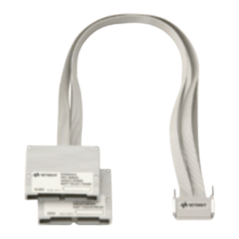
Overview, Installation, and Selection of Probing Options The E5405A-Pro Series 17-channel Differential Soft Touch Probe (for analyzers with 90-pin cable connectors) The Keysight E5405A-pro series probe is a 17-channel, single-ended, soft touch probe compatible with the Keysight logic analysis modules listed in Table 1 on page 12. -
Page 18: The E5406A-Pro Series 34-Channel Single-Ended Soft Touch Probe (For Analyzers With 90-Pin Cable Connectors)
Overview, Installation, and Selection of Probing Options The E5406A-Pro Series 34-channel Single-ended Soft Touch Probe (for analyzers with 90-pin cable connectors) The Keysight E5406A-pro series probe is a 34-channel, single-ended, soft touch probe compatible with the Keysight logic analysis modules listed in Table 1 on page 12. -
Page 19: The E5386A Half-Channel Adapter (For Use With The 16760A Logic Analyzer)
Overview, Installation, and Selection of Probing Options The E5386A Half-channel Adapter (for use with the 16760A logic analyzer) The E5386A Half-channel Adapter is intended to be used with the Keysight 16760A logic analyzer in half-channel state mode and supports the E5402A, E5405A, and E5406A probes. -
Page 20: Mechanical Considerations
Keysight E5400-Pro Series Soft Touch Connectorless Probes User’s Guide Mechanical Considerations Characteristics / 20 Probe Dimensions / 21 Board Layout Dimensions / 25 Pin Outs for the Probes / 29 E5386A Half-channel Adapter Dimensions / 39 Use the following mechanical information to design your target system board. -
Page 21: Characteristics
Mechanical Considerations Characteristics Electrical considerations such as equivalent probe loads, input impedance, and time domain transmission are shown in chapters 3 and 4 of this manual. Other characteristics are dependent on the logic analyzer module you are using. Keysight E5400-Pro Series Soft Touch User’s Guide Artisan Technology Group - Quality Instrumentation ... -
Page 22: Probe Dimensions
Mechanical Considerations Probe Dimensions The following figures show the dimensions of the Keysight E5400-pro series soft touch probes. Figure 6 E5402A probe dimensions Keysight E5400-Pro Series Soft Touch User’s Guide Artisan Technology Group - Quality Instrumentation ... Guaranteed | (888) 88-SOURCE | www.artisantg.com... - Page 23 Mechanical Considerations Figure 7 E5404A probe dimensions Keysight E5400-Pro Series Soft Touch User’s Guide Artisan Technology Group - Quality Instrumentation ... Guaranteed | (888) 88-SOURCE | www.artisantg.com...
- Page 24 Mechanical Considerations Figure 8 E5405A probe dimensions Keysight E5400-Pro Series Soft Touch User’s Guide Artisan Technology Group - Quality Instrumentation ... Guaranteed | (888) 88-SOURCE | www.artisantg.com...
- Page 25 Mechanical Considerations Figure 9 E5406A probe dimensions Keysight E5400-Pro Series Soft Touch User’s Guide Artisan Technology Group - Quality Instrumentation ... Guaranteed | (888) 88-SOURCE | www.artisantg.com...
-
Page 26: Board Layout Dimensions
Mechanical Considerations Board Layout Dimensions Use the following dimensions to layout your PC board pads and holes for use with the soft touch probes. Retention Module Dimensions Unless otherwise specified, dimensions are in inches and have the following tolerances. NOTE Linear X.X = +-0.1 X.XX = +-0.01... - Page 27 Mechanical Considerations Figure 11 E5412A retention module dimensions Figure 12 E5403A side-by-side dimensions Keysight E5400-Pro Series Soft Touch User’s Guide Artisan Technology Group - Quality Instrumentation ... Guaranteed | (888) 88-SOURCE | www.artisantg.com...
- Page 28 Mechanical Considerations Optimal board thickness for this top-side mount retention module is shown above. Retention modules can be hand soldered into thicker boards, but will not form a bottom-side solder fillet. Figure 13 E5412A side-by-side dimensions Keysight E5400-Pro Series Soft Touch User’s Guide Artisan Technology Group - Quality Instrumentation ...
-
Page 29: Footprint Dimensions
Mechanical Considerations Footprint Dimensions The retention module alignment is symmetrical around the pad footprint. Figure 14 Top view footprint dimensions (drawing notes next page). The above view is looking down onto the footprint on the printed-circuit NOTE board. Keysight E5400-Pro Series Soft Touch User’s Guide Artisan Technology Group - Quality Instrumentation ... -
Page 30: Pin Outs For The Probes
To get the latest Probes.xml file, go to . Install the file in c:\Program www.keysight.com/find/probe-definitions Files\Keysight Technologies\AddIns\Keysight\. Refer to the logic analyzer on-line help for more information. Keysight E5400-Pro Series Soft Touch User’s Guide Artisan Technology Group - Quality Instrumentation ... Guaranteed | (888) 88-SOURCE | www.artisantg.com... -
Page 31: Probing With E5404A-Pro Series Probe
Mechanical Considerations Probing with E5404A-Pro Series Probe The following footprint provides pin out and pad numbers for the E5404A single-ended probe for use with 40-pin logic analyzers. Logic analyzer CK 1+ odd pod Logic analyzer CK 2+ even pod Figure 15 Pad numbers for E5404A-pro series. * If you only plan to use the E5404A 40-pin probe with single-ended clocking to probe the following footprint, then A8 and B20 are unused. - Page 32 Mechanical Considerations If you ever plan on upgrading from a 40-pin to a 90-pin logic analyzer to take advantage of higher state speed and differential probing on the clock channel, some steps should be taken so that the original footprint will work for both the E5404A and the E5406A probes.
- Page 33 Mechanical Considerations E5404A 34-channel E5404A 34-channel Single-ended Probe Logic Analyzer Single-ended Probe Logic Analyzer Signal Name Pad # Channel Signal Name Pad # Channel → Whichever Ground Whichever pod is pod is connected to connected to → → "Odd" on the "Odd"...
-
Page 34: Probing With The E5405A-Pro Series Probe
→ → → Ground Probing with the E5405A-Pro Series Probe The following footprint provides pin out and pad numbers for the E5405A differential probe for use with 90-pin logic analyzers. Keysight E5400-Pro Series Soft Touch User’s Guide Artisan Technology Group - Quality Instrumentation ... Guaranteed | (888) 88-SOURCE | www.artisantg.com... - Page 35 Mechanical Considerations CLK- CLK+ D10+ D10- D11- D11+ D12+ D12- D13- D13+ D14+ D14- D15- D15+ Figure 16 Pad numbers for E5405A-pro series. E5405A Differential Logic Analyzer E5405A Differential Logic Analyzer Probe Probe Signal Pad# Channel Signal Pad# Channel Name Name →...
- Page 36 Mechanical Considerations E5405A Differential Logic Analyzer E5405A Differential Logic Analyzer Probe Probe Signal Pad# Channel Signal Pad# Channel Name Name → D2 (+) Ground D2 (-) D3 (-) → Ground D3 (+) → D4 (+) Ground D4 (-) D5 (-) →...
-
Page 37: Probing With The E5402A/E5406A-Pro Series Probe
Mechanical Considerations Probing with the E5402A/E5406A-Pro Series Probe The following footprint provides pin out and pad numbers for the E5402A/E5406A single-ended probe for use with 90-pin logic analyzers. Logic analyzer CK 1+ odd pod *GND/ CK1- Logic *GND/ CK 2- analyzer CK 2+ even pod... - Page 38 Mechanical Considerations E5402A/E5406A E5402A/E5406A 34-channel Single-ended Logic Analyzer 34-channel Single-ended Logic Analyzer Probe Probe Signal Name Pad # Channel Signal Name Pad # Channel → Whichever Ground Whichever pod is pod is connected to connected to → → "Odd" on the "Odd"...
- Page 39 Mechanical Considerations E5402A/E5406A E5402A/E5406A 34-channel Single-ended Logic Analyzer 34-channel Single-ended Logic Analyzer Probe Probe Signal Name Pad # Channel Signal Name Pad # Channel → Ground Whichever pod is connected to → Ground "Even" on the E5402A/ → → E5406A probe →...
-
Page 40: E5386A Half-Channel Adapter Dimensions
Mechanical Considerations E5386A Half-channel Adapter Dimensions The E5386A half-channel adapter works with the 16760A logic analyzer and the soft touch probes. Figure 18 E5386A dimensions Keysight E5400-Pro Series Soft Touch User’s Guide Artisan Technology Group - Quality Instrumentation ... Guaranteed | (888) 88-SOURCE | www.artisantg.com... -
Page 41: Pin Out For The E5386A Half-Channel Adapter When Connected To E5405A
Mechanical Considerations Pin out for the E5386A half-channel adapter when connected to E5405A When used with the E5405A-pro series differential soft touch probe, you need only one half-channel adapter. The table below shows the pin assignments. Figure 19 Half-channel adapter with E5405A-pro series Keysight E5400-Pro Series Soft Touch User’s Guide... - Page 42 Mechanical Considerations Table 4 Pin-out table for E5386A connected to an E5405A E5405A Differential Probe Negative Signals Positive Signals Logic Analyzer Signal Name Pin# Signal Name Pin# Channel → D0(-) D0(+) Whichever pod is plugged into bits 0-7 → D1(-) D1(+) →...
-
Page 43: Pin Out For Two E5386A Half-Channel Adapters Connected To One E5402A Or E5406A
Mechanical Considerations Pin out for two E5386A half-channel adapters connected to one E5402A or E5406A When used with the E5402A/E5406A-pro series single-ended soft touch probe, you need two half-channel adapters, one adapter for Odd data and one for Even data. The table below shows the pin assignments. The E5386A that is connected to the end of the E5402A/E5406A labeled ‘odd’... - Page 44 Mechanical Considerations Table 5 Pin-out table for two E5386A adapters connected to an E5402A or E5406A E5386A Adapter Odd E5386A Adapter Even E5402A/E5406A E5402A/E5406A 34-channel Single-ended Logic Analyzer 34-channel Single-ended Logic Analyzer Probe Probe Signal Name Pin # Channel Signal Name Pin # Channel →...
- Page 45 Mechanical Considerations Keysight E5400-Pro Series Soft Touch User’s Guide Artisan Technology Group - Quality Instrumentation ... Guaranteed | (888) 88-SOURCE | www.artisantg.com...
-
Page 46: Operating The E5404A-Pro Series Probes
Keysight E5400-Pro Series Soft Touch Connectorless Probes User’s Guide Operating the E5404A-Pro Series Probes Equivalent Probe Loads / 46 Time Domain Transmission (TDT) / 48 Electrical considerations such as equivalent probe loads, input impedance, and time domain transmission (TDT). Artisan Technology Group - Quality Instrumentation ... Guaranteed | (888) 88-SOURCE | www.artisantg.com... -
Page 47: Equivalent Probe Loads
Operating the E5404A-Pro Series Probes Equivalent Probe Loads The following probe load models are based on in-circuit measurements made with an Keysight 8753E 6 GHz network analyzer and an Keysight 54750A TDR/TDT using a 50 Ω test fixture. The following schematic accurately models the probe load out to 6 GHz. - Page 48 Operating the E5404A-Pro Series Probes Measured Modeled Modeled (simple) (complex) 6 8 1 5 6 8 1 5 6 8 1 5 6 8 1 5 6 8 1 100 k 10 M 100 M Frequency Figure 22 Measured versus modeled input impedance (E5404A) Keysight E5400-Pro Series Soft Touch User’s Guide Artisan Technology Group - Quality Instrumentation ...
-
Page 49: Time Domain Transmission (Tdt)
Operating the E5404A-Pro Series Probes Time Domain Transmission (TDT) All probes have a loading effect on the circuit when they come in contact with the circuit. Time domain transmission (TDT) measurements are useful for understanding the probe loading effects as seen at the target receiver. The following TDT measurements were made mid-bus on a 50Ω... - Page 50 Operating the E5404A-Pro Series Probes without probe with probe 500 ps per division Figure 24 TDT measurement at receiver with and without probe load for 150 ps rise time without probe with probe 500 ps per division Figure 25 TDT measurement at receiver with and without probe load for 250 ps rise time Keysight E5400-Pro Series Soft Touch User’s Guide Artisan Technology Group - Quality Instrumentation ...
- Page 51 Operating the E5404A-Pro Series Probes without probe with probe 500 ps per division Figure 26 TDT measurement at receiver with and without probe load for 500 ps rise time without probe with probe 500 ps per division Figure 27 TDT measurement at receiver with and without probe load for 1000 ps rise time Keysight E5400-Pro Series Soft Touch User’s Guide Artisan Technology Group - Quality Instrumentation ...
-
Page 52: Operating The E5402A, E5405A, And E5406A-Pro Series Probes
Keysight E5400-Pro Series Soft Touch Connectorless Probes User’s Guide Operating the E5402A, E5405A, and E5406A-Pro Series Probes Equivalent Probe Loads / 52 Time Domain Transmission (TDT) / 54 Step Inputs / 57 Eye Opening / 60 Electrical considerations such as equivalent probe loads, input impedance, time domain transmission (TDT), step inputs, and eye opening. -
Page 53: Equivalent Probe Loads
Operating the E5402A, E5405A, and E5406A-Pro Series Probes Equivalent Probe Loads The following probe load models are based on in-circuit measurements made with an Keysight 8753E 6 GHz network analyzer and an Keysight 54750A TDR/TDT using a 50 Ω test fixture. The following schematic accurately models the probe load out to 6 GHz. - Page 54 Operating the E5402A, E5405A, and E5406A-Pro Series Probes M odel M easured 10 1 6 8 1 5 6 8 1 5 6 8 1 5 6 8 1 5 6 8 1 10 0 k 10 M 10 0 M Frequency Figure 29 Measured versus modeled input impedance (E5402A, E5404A, and E5406A) Keysight E5400-Pro Series Soft Touch User’s Guide...
-
Page 55: Time Domain Transmission (Tdt)
Operating the E5402A, E5405A, and E5406A-Pro Series Probes Time Domain Transmission (TDT) All probes have a loading effect on the circuit when they come in contact with the circuit. Time domain transmission (TDT) measurements are useful for understanding the probe loading effects as seen at the target receiver. The following TDT measurements were made mid-bus on a 50Ω... - Page 56 Operating the E5402A, E5405A, and E5406A-Pro Series Probes Figure 31 TDT measurement at receiver with and without probe load for 100 ps rise time without probe with probe 500 ps per division Figure 32 TDT measurement at receiver with and without probe load for 250 ps rise time without probe with probe 500 ps per division...
- Page 57 Operating the E5402A, E5405A, and E5406A-Pro Series Probes without probe with probe 500 ps per division Figure 34 TDT measurement at receiver with and without probe load for 1000 ps rise time Keysight E5400-Pro Series Soft Touch User’s Guide Artisan Technology Group - Quality Instrumentation ... Guaranteed | (888) 88-SOURCE | www.artisantg.com...
-
Page 58: Step Inputs
Operating the E5402A, E5405A, and E5406A-Pro Series Probes Step Inputs Maintaining signal fidelity to the logic analyzer is critical if the analyzer is to accurately capture data. One measure of a system's signal fidelity is to compare V to V for various step inputs. - Page 59 Operating the E5402A, E5405A, and E5406A-Pro Series Probes EyeScan Scope 500 ps per division Figure 36 Logic analyzer’s response to 150 ps rise time EyeScan Scope 500 ps per division Figure 37 Logic analyzer’s response to 250 ps rise time Keysight E5400-Pro Series Soft Touch User’s Guide Artisan Technology Group - Quality Instrumentation ...
- Page 60 Operating the E5402A, E5405A, and E5406A-Pro Series Probes EyeScan Scope 500 ps per division Figure 38 Logic analyzer’s response to 500 ps rise time EyeScan Scope 500 ps per division Figure 39 Logic analyzer’s response to 1000 ps rise time Keysight E5400-Pro Series Soft Touch User’s Guide Artisan Technology Group - Quality Instrumentation ...
-
Page 61: Eye Opening
Operating the E5402A, E5405A, and E5406A-Pro Series Probes Eye Opening The eye opening at the logic analyzer is the truest measure of an analyzer's ability to accurately capture data. Seeing the eye opening at the logic analyzer is possible with Eye Scan. The eye opening viewed with Eye Scan helps the user know how much margin the logic analyzer has, where to sample and at what threshold. - Page 62 Operating the E5402A, E5405A, and E5406A-Pro Series Probes 500 ps per division Figure 41 Logic analyzer eye opening for a PRBS signal of 500 mV p-p, 800 MT/s data rate 500 ps per division Figure 42 Logic analyzer eye opening for a PRBS signal of 500 mV p-p, 1250 MT/s data rate Keysight E5400-Pro Series Soft Touch User’s Guide Artisan Technology Group - Quality Instrumentation ...
- Page 63 Operating the E5402A, E5405A, and E5406A-Pro Series Probes 500 ps per division Figure 43 Logic analyzer eye opening for a PRBS signal of 500 mV p-p, 1500 MT/s data rate 500 ps per division Figure 44 Logic analyzer eye opening for a PRBS signal of 200 mV p-p, 1500 MT/s data rate Keysight E5400-Pro Series Soft Touch User’s Guide Artisan Technology Group - Quality Instrumentation ...
-
Page 64: Circuit Board Design
Keysight E5400-Pro Series Soft Touch Connectorless Probes User’s Guide Circuit Board Design Transmission Line Considerations / 64 Recommended Routing / 65 Data and Clock Inputs per Operating Mode / 67 Thresholds / 70 Signal Access / 71 Design considerations when you layout your circuit board. Artisan Technology Group - Quality Instrumentation ... -
Page 65: Transmission Line Considerations
Circuit Board Design Transmission Line Considerations Stubs connecting signal transmission lines to the connector should be as short as feasible. Longer stubs will cause more loading and reflections on a transmission line. If the electrical length of a stub is less than 1/5 of the signal rise time, it can be modeled as a lumped capacitance. -
Page 66: Recommended Routing
Circuit Board Design Recommended Routing Two rows of compliant contacts in the probe make contact with pads laid down on the surface of the PC board. These contacts provide an extremely low probe load (<0.70 pF per channel), and make a good electrical connection with a small amount of compression force on a choice of standard PCB platings. - Page 67 Circuit Board Design Figure 46 17-bit differential routing (E5405A) Keysight E5400-Pro Series Soft Touch User’s Guide Artisan Technology Group - Quality Instrumentation ... Guaranteed | (888) 88-SOURCE | www.artisantg.com...
-
Page 68: Data And Clock Inputs Per Operating Mode
Circuit Board Design Data and Clock Inputs per Operating Mode The following table shows the number of data and clock inputs for each connector on your target system for the various operating modes of your logic analyzer. Table 6 16760A logic analyzer E5405A E5402A or E5406A 17-channel... - Page 69 Circuit Board Design - To realize 17 data inputs (in full-channel mode) while using time tags in addition to a clock input on a single 16760A module or on the master module in a multi-card set, you must route the data signals to pod 2 and the clock to pod 1. A convenient way to avoid laying out a second connector to connect only the clock signal is to use the Keysight E5382A flying-lead set to make the connection to the clock.
- Page 70 Circuit Board Design Table 8 1670 Series, 1680/90 Series, 16710/11/12A, 16715/16/17A, 16740/41/4A, 16750/51/52B, 16910/11A logic analyzers E5404A 34-channel Operating Mode single-ended soft touch Synchronous (state) analysis 32 data plus 2 clock inputs 250 Mb/s, 500 Mb/s, (see note 1) Timing mode 32 data plus 2 clock inputs (see note 1) Note 1: In 500 Mb/s mode, there is one clock input which must be routed to the clock...
-
Page 71: Thresholds
The threshold can be changed on a “per pod” basis (16 data + 1 clock). This is accomplished using the “user defined threshold” window in the logic analyzer software. E5405A-pro series differential soft touch probe Data inputs If you are using the E5405A differential soft touch probe to acquire... -
Page 72: Signal Access
E5386A Half-channel Adapter The E5386A can be used with the E5405A-pro series differential soft touch probe or the E5402A/E5406A-pro series single-ended probes to map the signals from the PC board pads to the 16760A when operating in half-channel state mode. - Page 73 Circuit Board Design Figure 47 E5386A Half-channeled adapter Keysight E5400-Pro Series Soft Touch User’s Guide Artisan Technology Group - Quality Instrumentation ... Guaranteed | (888) 88-SOURCE | www.artisantg.com...
-
Page 74: Recommended Reading
Keysight E5400-Pro Series Soft Touch Connectorless Probes User’s Guide Recommended Reading For More Information / 74 A list of recommended reading for more information about systems and high-speed digital design. Artisan Technology Group - Quality Instrumentation ... Guaranteed | (888) 88-SOURCE | www.artisantg.com... -
Page 75: For More Information
Designing High-speed Target Systems for Logic Analyzer Probing “Designing High-speed Target Systems for Logic Analyzer Probing” Keysight Technologies application note publication number 5988-2989EN. Keysight E5400-Pro Series Soft Touch User’s Guide Artisan Technology Group - Quality Instrumentation ... Guaranteed | (888) 88-SOURCE | www.artisantg.com... -
Page 76: Safety Notices
Safety Notices This apparatus has been designed and tested in accordance with IEC Publication 1010, Safety Requirements for Measuring Apparatus, and has been supplied in a safe condition. This is a Safety Class I instrument (provided with terminal for protective earthing). Before applying power, verify that the correct safety precautions are taken (see the following warnings). -
Page 77: To Clean The Instrument
To clean the instrument If the instrument requires cleaning: (1) Remove power from the instrument. (2) Clean the external surfaces of the instrument with a soft cloth dampened with a mixture of mild detergent and water. (3) Make sure that the instrument is completely dry before reconnecting it to a power source. - Page 78 Index retention module, probing, adapter, E5386A half-channel, analyzer, at a glance, E5386A half-channel adapter, labels, attach retention module, E5404A 34-chan single ended, 14, logic analyzer, design for probing, E5405A 17-chan differential, E5406A 34-chan single-ended, equivalent probe loads bottom-side attach, E5404A, MECL system design, E5405A, E5406A,...
- Page 79 Index reordered bits, replaceable part retention module, required number of probes, retention module attaching, dimensions, ordering, routing, safety symbols, selecting a probe, signal access, single-ended probe E5405A, 14, E5406A, solder retention module, state speed, step inputs, synchronous state analysis, thresholds, time domain transmission, E5404A, top-side attach,...
- Page 80 Keysight E5400-Pro Series Soft Touch User’s Guide Artisan Technology Group - Quality Instrumentation ... Guaranteed | (888) 88-SOURCE | www.artisantg.com...
- Page 81 This information is subject to change without notice. © Keysight Technologies 2014 November 2014 *E5404-97006* www.keysight.com Artisan Technology Group - Quality Instrumentation ... Guaranteed | (888) 88-SOURCE | www.artisantg.com...
- Page 82 Artisan Technology Group is your source for quality new and certified-used/pre-owned equipment SERVICE CENTER REPAIRS WE BUY USED EQUIPMENT • FAST SHIPPING AND DELIVERY Experienced engineers and technicians on staff Sell your excess, underutilized, and idle used equipment at our full-service, in-house repair center We also offer credit for buy-backs and trade-ins •...
Need help?
Do you have a question about the E5405A-Pro Series and is the answer not in the manual?
Questions and answers