
Related Manuals for Keysight Technologies E7515B UXM 5G


Summary of Contents for Keysight Technologies E7515B UXM 5G
- Page 1 Keysight Wireless Test Platform E7515B UXM 5G Wireless Test Platform Getting Started Guide...
-
Page 2: Safety Notices
COVERING THE MATERIAL IN THIS DOCUMENT THAT CONFLICT WITH government requirements THESE TERMS, THE WARRANTY beyond those set forth in the © Keysight Technologies, Inc. TERMS IN THE SEPARATE EULA shall apply, except to the 2014-2019 AGREEMENT WILL CONTROL. extent that those terms, rights, or... - Page 3 Where to Find the Latest Information Documentation is updated periodically. For the latest information about these products, including instrument software upgrades, application information, and product information, browse to one of the following URLs, according to the name of your product: http://www.keysight.com/find/e7515B To receive the latest updates by email, subscribe to Keysight Email Updates at the following URL: http://www.keysight.com/find/MyKeysight...
-
Page 5: Table Of Contents
Contents Table of Contents Introduction 9 Overview 10 Purpose and Function 10 Differences between E7515B and E7515E 11 Millimeter-Wave Accessory Instruments 16 Reference Documents 18 Instrument Information and Maintenance 19 Size and Weight 19 Power Requirements 19 Electrical Safety 19 Environmental Conditions 21 EMI and EMC Compliance 21 Ventilation 21... - Page 6 Contents The Control Panel 46 Viewing the Control Panel 46 Control Panel Icons 47 HCCU Functions 49 Hardware Configuration Control Utility (HCCU) 50 Viewing the HCCU 51 HCCU Tabs 52 System Tab 53 Change Setup 56 Scenario Tab 60 Information Tab 61 Calibration Tab 62 Tools Tab 63 HCCU Configuration Icon (gear symbol) 66...
- Page 7 Hard Drive Partitioning and Use 94 Disk Drive Recovery Process 95 Updating the Keysight E7515B UXM 5G software 99 Using the E7515B/E7515B UXM 5G Firmware Update Tool 99 Updating the Keysight 5G NR Test Application 101 Updating the Application 101...
- Page 8 Contents Getting Started Guide...
-
Page 9: Introduction
Keysight Wireless Test Set E7515B UXM 5G Wireless Test Platform Getting Started Guide Introduction The following topics can be found in this section: “Overview” on page 10 “Instrument Information and Maintenance” on page 19 “UXM 5G Software Applications” on page 24... -
Page 10: Overview
The purpose of this guide is to provide you with the basic steps for getting started with the Keysight E7515B UXM 5G Wireless Test Platform, and to tell you where you can go to get additional information. It also provides first-time power on instructions, licensing information, operating system information, and general hardware information. -
Page 11: Differences Between E7515B And E7515E
Introduction Overview Differences between E7515B and E7515E The E7515B model of the UXM 5G differs from the economy version (E7515E) in that it includes circuit boards which the economy version omits., and it omits some internal circuit boards. Consequently, it has some limitations on functionality, and particularly on RF port usage, which are explained here for the benefit of users who may be familiar with the UXM 5G in its E7515B version. - Page 12 Introduction Overview Figure 1-3 Overall block diagram of the RFIO board The diagram above shows signal routing through the RFIO board (it is simplified, omitting certain paths used for reference or calibration signals). In the E7515E, a maximum of eight RF ports can be used at a time. All eight can be transmit ports, provided no ports are being used as receive ports.
- Page 13 Introduction Overview The diagram below shows how transmit signals are routed to the front panel RF ports. In this example, ports RF 1, RF 2, and RF 3 are used. Figure 1-4 Tx paths to the front panel RF ports Getting Started Guide...
- Page 14 Introduction Overview The diagram below shows how receive signals are routed from the front panel RF ports. The signal routing is more complex than in the case of transmit signals. The receive path from either of two RF ports (RF 2 or RF 6, in this example) must go through the switch highlighted in yellow.
- Page 15 Introduction Overview The RF paths involved in a simple port setup (output on RF 1/2/3, input on RF 6) are illustrated in Figure 1-6. Figure 1-6 RF path example: RF 1 (Tx), RF 2 (Tx), RF 3 (Tx) and RF 6 (Rx) Getting Started Guide...
-
Page 16: Millimeter-Wave Accessory Instruments
Introduction Overview Millimeter-Wave Accessory Instruments For testing at higher frequencies than the UXM itself can generate, two other instruments are commonly used with the UXM: the M1740A mmWave Transceiver (usually called the Remote Radio Head or RRH) and the E7770A Common Interface Unit (usually called the CIU). - Page 17 Introduction Overview As illustrated below, the CIU is able to upconvert the RF output of the UXM to the 6-12 GHz range (the lower portion of the picture), and apply this signal to the DUT. On the same path, it also can accept a return signal from the DUT, downconvert it to the range of the UXM, and return it to an input port on the UXM.
-
Page 18: Reference Documents
Product documents included there include: — E7515B UXM 5G Wireless Test Platform - User's and Programmer's Guide — E7515B UXM 5G Wireless Test Platform - Configuration Guide — 5G NR Online documentation (help files) for the UXM 5G Test Applications. -
Page 19: Instrument Information And Maintenance
Introduction Instrument Information and Maintenance Instrument Information and Maintenance Size and Weight The weight and dimensions of the E7515B are as follows: — Weight: 42.2 kg (with 2 cells) — Height: 309 mm (323 mm with feet) — Width: 436 mm (452.5 with lateral handles) —... - Page 20 Introduction Instrument Information and Maintenance This instrument has an auto-ranging line voltage input. Ensure the supply voltage is within the specified range and the rating for the service breaker is correct. When installing the product in a cabinet the convection into and out of the product must not be restricted.
-
Page 21: Environmental Conditions
Introduction Instrument Information and Maintenance Environmental Conditions This product is designed for use in Installation Category II and Pollution Degree 2 environment. This product is designed for use in the following conditions: — For indoor use only — Operating Temperature 10° C to 40° C, 5% to 85% (non-condensing) relative humidity —... -
Page 22: Instrument Maintenance
Cleaning the Instrument To prevent electrical shock, disconnect the Keysight Technologies Model E7515B from mains before cleaning. Use a dry cloth or one slightly dampened with water to clean the external case parts. Do not attempt to clean internally. - Page 23 Introduction Instrument Information and Maintenance — Be sure that all instruments are properly earth-grounded to prevent build-up of static charge. Additional information about ESD For more information about ESD and how to prevent ESD damage, contact the Electrostatic Discharge Association: http://www.www.esda.org The ESD standards developed by this agency are sanctioned by the American National Standards Institute (ANSI).
-
Page 24: Uxm 5G Software Applications
Introduction UXM 5G Software Applications UXM 5G Software Applications The UXM 5G operates within the C8700200A 5G Test Application Framework. Different capabilities of this framework are licensed separately, as listed below: You must purchase a Test Application license to use its features in the UXM 5G. Licenses The license numbers given here are simplified;... -
Page 25: About The Test Applications
Installing the Test Applications This software comes already installed on your UXM 5G. If there is a problem and you need to re-install it, refer to Installing the Software on “Updating the Keysight E7515B UXM 5G software” on page Getting Started Guide... - Page 26 Introduction UXM 5G Software Applications Getting Started Guide...
-
Page 27: Quick Start
Keysight Wireless Test Set E7515B UXM 5G Wireless Test Set Platform Getting Started Guide 2 Quick Start This section describes how to set up your UXM 5G, install product licenses, and provide test platform maintenance. You can also contact your Keysight representative to obtain on-site start-up assistance to help you with all steps outlined in this section, which is included with your UXM 5G purchase. -
Page 28: Initial Inspection
Inspect the shipping container and the cushioning material for signs of stress. Retain undamaged shipping materials for future use, as you may wish to ship the test platform to another location or to Keysight Technologies for service. Verify the contents of the container against the table below. -
Page 29: Shipping Problems
— Contact the nearest Keysight Technologies office. — Keep the shipping materials for the carrier’s inspection. — If you must return a test platform to Keysight Technologies, use the undamaged original or comparable shipping materials. See “Returning Your Test Set for Service” on page 107. -
Page 30: Instrument Location And Rack Mounting Requirements
Quick Start Instrument Location and Rack Mounting Requirements Instrument Location and Rack Mounting Requirements Locating the Test Platform Make sure that the left-side panel fan inlet and right-side panel exhaust vent areas are not obstructed. The minimal required clearance is 2.75 inches (7 cm). Install the instrument so that the detachable power cord is readily identifiable and is easily reached by the operator. - Page 31 Quick Start Instrument Location and Rack Mounting Requirements VENTILATION REQUIREMENTS: When installing the instrument(s) into a cabinet consideration shall be given to the convection flow into and out of the cabinet. Consideration shall also be given to the individual instruments to avoid having the heated discharge of one instrument, now becoming the cooling intake air for another instrument.
-
Page 32: Turning On The Test Platform The First Time
Quick Start Turning On the Test Platform the First Time Turning On the Test Platform the First Time DO NOT remove the AC power during boot-up/shutdown of the operating system or during the process of initializing the software. This can cause damage to the system files and prevent proper operation of the instrument. - Page 33 (EULA). After you agree to the EULA, the operating system boots-up and you see a black background with Keysight Technologies logo displayed on the screen. The E7515B Control Panel (shown below) is overlaid on top of this Keysight screen and remains visible while the internal hardware boards of the UXM 5G are booted-up.
- Page 34 Quick Start Turning On the Test Platform the First Time Step Action Notes 5. Wait until you see The changing colors of the E7515B the green or red Control Panel pictorial graphic indicate color displayed in the “ready-state” of the UXM 5G. the UXM 5G pictorial graphic, located in the...
- Page 35 Quick Start Turning On the Test Platform the First Time Step Action Notes 9. Select a scenario. In the HCCU, on the Scenarios tab, select a testing scenario (such as NR5GFormatOpt03_RF) and click the Activate icon. Wait while the selection is set up (an "in progress"...
- Page 36 Quick Start Turning On the Test Platform the First Time Step Action Notes 13. Begin using your For detailed information on how to use new software after the software, refer to the 5G NR Test the splash screen Application Help. disappears.
-
Page 37: Shutting Down The Test Platform
Quick Start Turning On the Test Platform the First Time Shutting Down the Test Platform Step Action Notes 1. Close the test application by clicking on the "X" button at the upper right. 2. It is recommended The display will show the windows that you press the shut-down screen. -
Page 38: Licensing
Quick Start Licensing Licensing All licenses required to operate your UXM 5G have been installed at the factory (except transportable licenses – see below) and can be recovered using one of the procedures outlined in Chapter 6, “Test Platform Operating System”, on page 87. -
Page 39: Transportable Licenses
> Keysight License Manager Help and search for “transport” to find detailed instructions.) Transportable licenses for the E7515B UXM 5G allow you to transport licenses up to 30 times within the previous 10 days. You can also save a transportable license to Keysight Software Manager (KSM) for later assignment to a host. -
Page 40: Lan Connectivity
Quick Start LAN Connectivity LAN Connectivity The UXM 5G has two network interface cards (NICs) that connect the instrument Host PC (embedded PC module) to external LAN outputs. If your site network supports Dynamic Host Configuration Protocol (DHCP), these front and rear LAN ports are assigned IP addresses automatically when they are connected to the LAN. -
Page 41: Windows Updates
Quick Start Windows Updates Windows Updates To ensure that your E7515B instrument is protected against the latest malware and viruses, it is recommended to install all the Windows critical updates. 1. Go to Windows/Start and type "Update"; click on the displayed Windows Update link: 2. - Page 42 Quick Start Windows Updates 3. •In order to keep your instrument protected, select Change settings in the left side menu: 4. Under Important updates, select the option Check for updates but let me choose whether to download and install them. Current Keysight policy sets the Windows Update settings to “Check for updates but let me choose whether to download and install them”...
-
Page 43: Anti-Virus Protection And Firewalls
Quick Start Anti-virus Protection and Firewalls Anti-virus Protection and Firewalls The instrument is shipped with the Windows 7.0 firewall disabled. No anti-virus software is shipped with the instrument. It is recommended that you do not enable anti-virus protection for normal operation. Take care to verify that USB memory devices used with the UXM 5G are virus-free before using with the instrument. - Page 44 Quick Start Anti-virus Protection and Firewalls Getting Started Guide...
-
Page 45: Control Panel Functions
Keysight Wireless Test Set E7515B UXM 5G Wireless Test Set Platform Getting Started Guide 3 Control Panel Functions The following topics can be found in this section: “Viewing the Control Panel” on page 46 “Control Panel Icons” on page 47... -
Page 46: The Control Panel
Control Panel Functions The Control Panel The Control Panel Figure 3-1 The UXM 5G Control Panel The E7515B Control Panel enables you to interact with and manage the hardware components of the UXM 5G. It is always running if the test platform is turned on. -
Page 47: Control Panel Icons
The functions listed in the table below are available by selecting the various E7515B Control Panel icons. For more information about these functions, see the "E7515B UXM 5G Wireless Test Platform - User's and Programmer's Guide", which is available in the Document Library tab of this site: http://www.keysight.com/find/uxm... - Page 48 Control Panel Functions The Control Panel Getting Started Guide...
-
Page 49: Hccu Functions
Keysight Wireless Test Set E7515B UXM 5G Wireless Test Set Platform Getting Started Guide 4 HCCU Functions The following topics can be found in this section: — System (system status information and operational controls) — Scenario (measurement format management) — Information (information on current hardware and software configuration) —... -
Page 50: Hardware Configuration Control Utility (Hccu)
HCCU Functions Hardware Configuration Control Utility (HCCU) Hardware Configuration Control Utility (HCCU) Figure 4-1 The HCCU Display The HCCU enables you to control the hardware configuration of the E7515B and other equipment it is used with. The HCCU (which appears in a browser window) is always running if the test platform is turned on. -
Page 51: Viewing The Hccu
HCCU Functions Hardware Configuration Control Utility (HCCU) Viewing the HCCU Right-click on the Keysight HCCU icon from the task bar and select Open HCCU. If you are unable to access the task bar, connect the USB keyboard to the UXM 5G using one of the USB ports located on the front and rear of the UXM 5G. -
Page 52: Hccu Tabs
HCCU Functions Hardware Configuration Control Utility (HCCU) HCCU Tabs The HCCU window has a tabbed interface. The tabs are: — System (system status information and operational controls) — Instruments (information on current hardware configuration) — Setup (hardware configuration selection) — Scenarios (measurement format management) —... -
Page 53: System Tab
HCCU Functions System Tab System Tab The System tab shows the hardware resources, represented as large icons (in the example illustrated below, a PC and an E7515E UXM 5G Base Wireless Test Platform). Figure 4-2 The System tab Using a mouse to move the cursor over a hardware icon causes two icons to appear, which provide access to additional information about the instrument represented. - Page 54 HCCU Functions System Tab Clicking the globe-shaped icon brings up detailed hardware status in a browser window, as illustrated below. Figure 4-4 Hardware Status Getting Started Guide...
- Page 55 HCCU Functions System Tab The System tab includes a Reset button (which can be used to reset all connected hardware resources) a Reboot button, and a Restart button. Figure 4-5 Reset, Reboot, Restart, Export Logs The System tab also includes an Export Logs button, which can be used to export logged information to a specified file location (proceeding with the export requires you to click OK in a confirmation window).
-
Page 56: Change Setup
HCCU Functions System Tab Change Setup The System tab also includes a Change Setup button, which opens a wizard window for selecting different hardware connections to the UXM 5G. Figure 4-6 Change Setup wizard Getting Started Guide... - Page 57 HCCU Functions System Tab The wizard includes a dropdown selector for various possible setups. Figure 4-7 Select new setup The wizard makes it possible to add optional devices. Figure 4-8 Optional Devices Getting Started Guide...
- Page 58 HCCU Functions System Tab The wizard includes a large selection of connection layout diagrams. Figure 4-9 Connection Layout The wizard includes a Detect Instruments feature, which can be used for connectivity checking. Figure 4-10 Detect Instruments Getting Started Guide...
- Page 59 HCCU Functions System Tab The wizard includes a Configure Instruments feature and a Summary page. Figure 4-11 Configure Instruments and Summary Getting Started Guide...
-
Page 60: Scenario Tab
HCCU Functions Scenario Tab Scenario Tab The Scenario tab provides information about the connection scenarios available for the connected hardware. Figure 4-12 Scenario tab Getting Started Guide... -
Page 61: Information Tab
HCCU Functions Information Tab Information Tab The Information tab provides access to Software and Hardware information about connected instruments. Use the up and down arrows to the right to show or hide particular information items. Figure 4-13 Information Tab Getting Started Guide... -
Page 62: Calibration Tab
HCCU Functions Calibration Tab Calibration Tab The Calibration tab provides access to path loss corrections for the system. Figure 4-14 Calibration tab Getting Started Guide... -
Page 63: Tools Tab
HCCU Functions Tools Tab Tools Tab The Tools tab provides access to the Signals Status and iPerf tools. Figure 4-15 Tools tab Getting Started Guide... - Page 64 HCCU Functions Tools Tab The Signals Status tool provides information on NE mode, DL cells, UL cells, and DAQs. Figure 4-16 Signals Status tool Getting Started Guide...
- Page 65 HCCU Functions Tools Tab The iPerf tool allows you to run the integrated traffic generator, a network testing tool used primarily to establish the maximum throughput of a client/server link. Figure 4-17 iPerf tool Getting Started Guide...
-
Page 66: Hccu Configuration Icon (Gear Symbol)
HCCU Functions HCCU Configuration Icon (gear symbol) HCCU Configuration Icon (gear symbol) This icon provides access to some settable properties of the HCCU interface. Figure 4-18 HCCU Configuration Help ("?" Icon) The Help tab provides access to HCCU documentation. Figure 4-19 Help tab Getting Started Guide... -
Page 67: Uxm Arrays
HCCU Functions UXM Arrays UXM Arrays The Control Panel was formerly used to add the UXM to an array ("Array Mode") containing a second UXM, or to run it independently of an array ("StandAlone Mode"). The HCCU now performs this type of configuration. The UXM runs in "StandAlone"... - Page 68 HCCU Functions UXM Arrays In the new setup, is necessary to increase the number of E7515Bs from 1 to 2, and to select from the dropdown list a named setup beginning with "TSPC_2UXM5G". Figure 4-21 Selecting an array setup Further requirements are described on the next page. Getting Started Guide...
- Page 69 HCCU Functions UXM Arrays It is also necessary to connect the E7515Bs to the Test PC by way of Ethernet cables and Ethernet switches, and to connect the E7515Bs to each other using RIO and Sync cables. The Change Setup wizard illustrates the connection requirements, under Connection Layout.
- Page 70 HCCU Functions UXM Arrays Getting Started Guide...
-
Page 71: Front And Rear Panel Functions
Keysight Wireless Test Set E7515B UXM 5G Wireless Test Set Platform Getting Started Guide 5 Front and Rear Panel Functions The following topics can be found in this section: “Front Panel Features” on page 72 “Rear Panel Features” on page 75... -
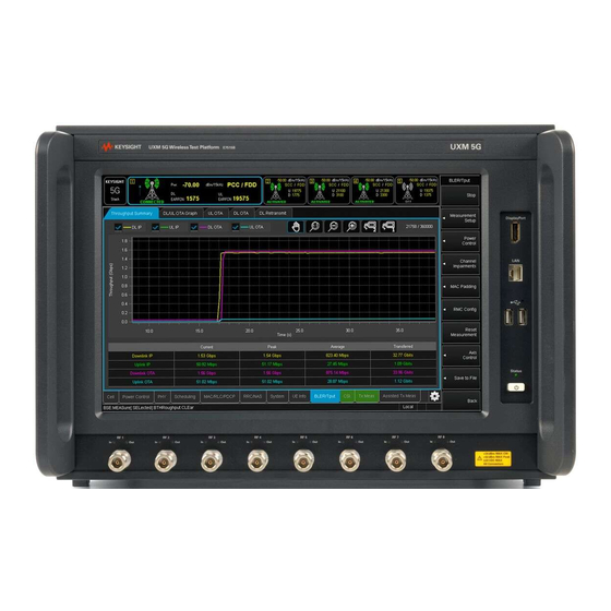
Page 72: Front Panel Features
Front and Rear Panel Functions Front Panel Features Front Panel Features Begin using the UXM 5G by becoming familiar with the layout of the Front Panel and the displayed user interface. Figure 5-1 UXM 5G Front Panel Getting Started Guide... - Page 73 Front and Rear Panel Functions Front Panel Features Number Item Name Description Touch-screen LCD Flat-Panel Display with single touch 15” capacitive touch-screen. DisplayPort This is a DisplayPort output, which transfers uncompressed video and audio data to an external display, such as a PC monitor or projector. If a monitor is going to be connected to the DisplayPort, it is preferable to make this connection while instrument power is off.
-
Page 74: Power Status Indicator
Front and Rear Panel Functions Front Panel Features Power Status Indicator UXM 5G Power Status — Off: Back-panel power switch is off. — Yellow: The rear power switch is on, but the UXM 5G is powered down. The first time the back-panel power switch is turned on (UXM 5G (front-panel switch is off). -
Page 75: Rear Panel Features
Front and Rear Panel Functions Rear Panel Features Rear Panel Features Figure 5-2 UXM 5G Rear Panel The regions of the rear panel that are outlined in the illustration are described in the following sections. Do not cover or block the air flow vents. The test platform draws air in from the left side and exhausts air from the right side. -
Page 76: Vdtamc Cards
Front and Rear Panel Functions Rear Panel Features VDTAMC Cards Figure 5-3 UXM 5G Rear Panel -- VDTAMC card connectors These connectors relate to the VDTAMC card (of which there are three, in slots 2, 4, and 5) within the UXM 5G. The VDTAMC card (also known as the Vadatech AMC 702) handles processing of the PHY and PDCP layers in the simulated 5G NR stack. -
Page 77: Cctamc Card
Front and Rear Panel Functions Rear Panel Features CCTAMC Card Figure 5-4 UXM 5G Rear Panel -- CCTAMC card connectors These connectors relate to the CCTAMC card within the UXM 5G. The CCTAMC card (also known as the Concurrent Technologies AMC14) handles processing of the RLC and MAC layers in the simulated 5G NR stack. -
Page 78: Fpga Expansion Module (E7515B-Fp1)
Front and Rear Panel Functions Rear Panel Features FPGA Expansion Module (E7515B-FP1) Figure 5-5 UXM 5G Rear Panel -- E7515B-FP1 card connectors These connectors relate to the optional FPGA expansion module (E7515B-FP1), of which there are potentially two, located in slots 1 and 3. These modules expand the FPGA capacity of the E7515B, for certain kinds of 5G testing which require this. -
Page 79: Auxm Connectors
Front and Rear Panel Functions Rear Panel Features AUXM Connectors Figure 5-6 UXM 5G Rear Panel -- AUXM Connectors These connectors relate to the AUXM circuit board within the UXM 5G. Name Description Notes I/0 1 SMA connectors (Reserved for future use.) I/O 2 AUX 1 SMA connectors... -
Page 80: Icm Connectors
Front and Rear Panel Functions Rear Panel Features ICM Connectors Figure 5-7 UXM 5G Rear Panel -- ICM Connectors These connectors relate to the AUXM circuit board within the UXM 5G. Name Description Notes GbE 4 This is the Ethernet port that The IP address for this input is labeled “ICM GbE4”. -
Page 81: Dcb+ Connectors
Front and Rear Panel Functions Rear Panel Features DCB+ Connectors Figure 5-8 UXM 5G Rear Panel -- DCB+ Connectors These connectors relate to the DCB+ circuit board within the UXM 5G. (There is a second board, with an identical set of connectors for it.) Name Description Notes... -
Page 82: Pcm
Front and Rear Panel Functions Rear Panel Features Figure 5-9 UXM 5G Rear Panel -- PCM Connectors These connectors relate to the DCB+ circuit board within the UXM 5G. Name Description Notes SS USB Four USB 3.0 ports. (The front-panel USB ports are USB 2.0.) Audio In 3.5 mm stereo Audio jack connector for input. -
Page 83: Rfio
Front and Rear Panel Functions Rear Panel Features RFIO Figure 5-10 UXM 5G Rear Panel -- RFIO Connectors These connectors relate to the RFIO circuit board within the UXM 5G. Name Description Notes IF IN 3 (Reserved for future use.) IF IN 4 (Reserved for future use.) IF OUT 8... -
Page 84: Front And Rear Panel Symbols
Front and Rear Panel Functions Front and Rear Panel Symbols Front and Rear Panel Symbols Symbol Description This symbol is used to indicate power ON. This symbol is used to indicate power OFF. This symbol is used to indicate power STANDBY mode (yellow in standby, green when instrument is ON). - Page 85 Front and Rear Panel Functions Front and Rear Panel Symbols Symbol Description Indicates the time period during which no hazardous or toxic substance elements are expected to leak or deteriorate during normal use. Forty years is the expected useful life of the product. This symbol on all primary and secondary packaging indicates compliance to China standard GB 18455-2001.
- Page 86 Front and Rear Panel Functions Front and Rear Panel Symbols Getting Started Guide...
-
Page 87: Test Platform Operating System
The following topics can be found in this section: “Keysight Software Installed” on page 88 “User Accounts” on page 89 “System Maintenance” on page 93 Updating the Keysight E7515B UXM 5G software on page 99 Updating the Keysight 5G NR Test Application on page 101... -
Page 88: Keysight Software Installed
If for some reason you need to re-install any software you purchased, go to www.keysight.com/find/softwaremanager to obtain the latest version. Refer to Chapter , “Updating the Keysight E7515B UXM 5G software”, on page 99 for software installation instructions. Uninstalling Keysight Software Uninstallation is a dialog driven process. -
Page 89: User Accounts
— Change Windows settings (e.g., using Device Manager) — Change the time and date — Run Keysight applications For instruments with a Keysight Technologies disk image, the Administrator account ships from the factory with the password set as: Keysight4u! Getting Started Guide... -
Page 90: Changing Account Passwords
Test Platform Operating System User Accounts Changing Account Passwords In order to minimize an “unnoticed” or “involuntary” change of the Administrator account password, the account properties have been set to restrict password change. If you need to change the password for this account, proceed as follows: Step Notes... - Page 91 Test Platform Operating System User Accounts Step Notes 4. Locate and select Users Administrator More Actions Properties 5. Clear the check box next to “User cannot change password” and then select Getting Started Guide...
- Page 92 Test Platform Operating System User Accounts Step Notes 6. After you have changed the Administrator Properties, change your password by pressing Ctrl+Alt+Del then Change Password 7. Enter the password change information. a. The account to be changed ("Administrator"). b. The old password c.
-
Page 93: System Maintenance
Test Platform Operating System System Maintenance System Maintenance Back-up It is recommended that you have a regular back-up strategy. Your IT department may already have a back-up strategy in place which is suitable for the test platform and its data. The Windows 10 operating system has a Backup utility that you can use to archive files and folders in case of a hard disk drive failure. -
Page 94: Hard Drive Partitioning And Use
Test Platform Operating System System Maintenance Hard Drive Partitioning and Use The drive is partitioned into 3 sections: C:, D: and E: — The C: partition contains the Windows 10 operating system and software installed by Keysight. This is an Open System which means you can install additional software. -
Page 95: Disk Drive Recovery Process
Help and Support Center. This recovery process should only be used for the repair/restoration purposes described above. It is not suitable for performing an instrument software update; “Updating the Keysight E7515B UXM 5G software” on page 99 for the appropriate procedure. - Page 96 Test Platform Operating System System Maintenance Using the Instrument Image Recovery System - Test Platform Operating System Step Notes 1. Turn on the The Windows Boot Manager Screen is displayed. instrument. Press the down arrow key to move the highlight to Image Instrument Recovery System...
- Page 97 Test Platform Operating System System Maintenance Step Notes 3. Review the terms. Select the “X” in the upper right corner to close this window. 4. Accept the license agreement by selecting Getting Started Guide...
- Page 98 Test Platform Operating System System Maintenance Step Notes 5. When the Instrument Image Recovery System has booted, follow the on-screen instructions to recover the image of the C: drive. Type in the number then press select “Recovery of the original factory system image”.
-
Page 99: Updating The Keysight E7515B Uxm 5G Software
Test Platform Operating System Updating the Keysight E7515B UXM 5G software Updating the Keysight E7515B UXM 5G software The following steps are required to upgrade your Keysight E7515B UXM 5G firmware. Downgrading to an earlier version is also possible, using the same process. - Page 100 Test Platform Operating System Updating the Keysight E7515B UXM 5G software Step Notes 9. The “UXM5G Update Tool” will continue by itself after the instrument restarts, and will finish the update. Then a confirmation button will be shown. 10. In case of an error during To manually repair the software upgrade, go to “Control...
-
Page 101: Updating The Keysight 5G Nr Test Application
Test Platform Operating System Updating the Keysight 5G NR Test Application Updating the Keysight 5G NR Test Application The following steps are required to update your Keysight UXM 5G software with the Keysight 5G NR Test Application. This software is licensed. Look for latest software versions at: http://www.keysight.com/find/softwaremanager Updating the Application Step... - Page 102 Test Platform Operating System Updating the Keysight 5G NR Test Application Step Notes Keysight E7515B 5. Scroll to find the Uninstall application, and select 6. When prompted to completely remove The UXM 5G Control Panel should be closed at the beginning of the selected application and all of its the uninstallation.
- Page 103 Installation of Third Party Software It is recommended that you do not install any non-approved software on the UXM 5G. Installation of third party software on the UXM 5G may render the system inoperative and is not supported by Keysight Technologies. Getting Started Guide...
- Page 104 Test Platform Operating System Updating the Keysight 5G NR Test Application Getting Started Guide...
-
Page 105: Troubleshooting
Keysight Wireless Test Set E7515B UXM 5G Wireless Test Set Platform Getting Started Guide 7 Troubleshooting The following topics can be found in this section: “Identifying Problems” on page 106 “Returning Your Test Set for Service” on page 107... -
Page 106: Identifying Problems
Troubleshooting Identifying Problems Identifying Problems No operator serviceable parts inside. Refer servicing to qualified personnel. To prevent electrical shock do not remove covers. 1. Select the Reboot button on the System tab of the HCCU utility whenever the UXM 5G hardware and/or software appear to be in a faulty state. Once the UXM 5G image shows a green check mark, the UXM 5G is in the ready state and you can proceed with your testing. -
Page 107: Returning Your Test Set For Service
Returning Your Test Set for Service Calling Keysight Technologies Keysight Technologies has offices around the world to provide you with complete support for your wireless test set. To obtain servicing information, or to order replacement parts, contact the nearest Keysight Technologies office listed under “Locations for Keysight Technologies”... -
Page 108: Locations For Keysight Technologies
Troubleshooting Returning Your Test Set for Service Locations for Keysight Technologies For online assistance: http://www.keysight.com/find/assist To contact Keysight Technologies: http://www.keysight.com/find/contactus Alternately, contact the nearest Keysight sales office: Americas Canada Brazil Mexico (877) 894 4414 55 11 3351 7010 001 800 254 2440... - Page 109 This information is subject to change without notice. © Keysight Technologies 2014-2019 Edition 1, August 2019 E7515-90024 www.keysight.com...
Need help?
Do you have a question about the E7515B UXM 5G and is the answer not in the manual?
Questions and answers