
Related Manuals for Keysight Technologies E4982A


Summary of Contents for Keysight Technologies E4982A
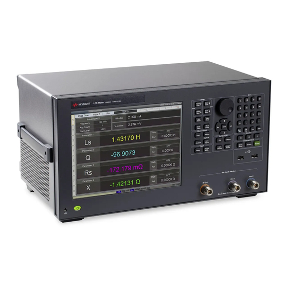
- Page 1 Test Equipment Depot - 800.517.8431 - 99 Washington Street Melrose, MA 02176 - TestEquipmentDepot.com Keysight E4982A LCR Meter Installation Guide...
- Page 4 Notices © Keysight Technologies 2012, 2015 Manual Part Number ware” as defined in DFAR 252.227-7014 (June 1995), or as a “commercial item” as No part of this manual may be reproduced E4982-90000 defined in FAR 2.101(a) or as “Restricted in any form or by any means (including computer software”...
- Page 5 Caution Do not exceed the operating input power, voltage, and current level and signal type appropriate for the instrument being used, refer to your instrument's Function Reference. Electrostatic discharge (ESD) can damage the highly sensitive microcircuits in your instrument. ESD damage is most likely to occur as the test fixtures are being connected or disconnected.
- Page 6 When you notice any of the unusual conditions listed below, immediately terminate operation and disconnect the power cable. Contact your local Keysight Technologies sales representative or authorized service company for repair of the instrument. If you continue to operate without repairing the instrument, there is a potential fire or shock hazard to the operator.
- Page 7 Manufacturer’s Declaration Herstellerbescheinigung GERA- USCHEMISSION LpA < 70 dB am Arbeitsplatz normaler Betrieb nach DIN 45635 T. 19 Manufacturer's Declaration ACOUSTIC NOISE EMISSION LpA < 70 dB operator position normal operation per ISO 7779 LCR Meter...
-
Page 8: Regulatory Compliance Information
This product complies with the essential requirements of the following applicable European Directives, and carries the CE marking accordingly: • The Low Voltage Directive 2006/95/EC • The EMC Directive 2004/108/EEC To obtain Declaration of Conformity, please contact your local Keysight Technologies sales office, agent or distributor. LCR Meter... -
Page 9: Safety Notice Supplement
Safety Notice Supplement • This equipment complies with EN/IEC61010- 1:2001. • This equipment is of MEASUREMENT CATEGORY I (CAT I). Do not use for CAT II, III, or IV. • Do not connect the measuring terminals to mains. • This equipment is a POLLUTION DEGREE 2, INDOOR USE product. - Page 10 N O T E POLLUTION DEGREE 2 in IEC61010-1. The E4982A is an INDOOR USE product. The LEDs in the E4982A are Class 1 in accordance with IEC60825-1, N O T E CLASS 1 LED PRODUCT. • Ground the Instrument To avoid electric shock, the instrument chassis and cabinet must be grounded with the supplied power cable’s...
- Page 11 To avoid the danger of introducing additional hazards, do not install substitute parts or perform unauthorized modifications to the instrument. Return the instrument to a Keysight Technologies Sales and Service Office for service and repair to ensure that safety features are maintained in operational condition.
- Page 12 Safety Symbols General definitions of safety symbols used on the instrument or in manuals are listed below. Instruction Manual symbol: the product is marked with this symbol when it is necessary for the user to refer to the instrument manual. Alternating current.
- Page 13 Exclusive Remedies The remedies provided herein are Buyer’s sole and exclusive remedies. Keysight Technologies shall not be liable for any direct, indirect, special, incidental, or consequential damages, whether based on contract, tort, or any other legal theory. Assistance...
- Page 14 The installation guide (this manual) provides start up setup information when you use the E4982A for the first time and troubleshooting information when the Windows cannot be boot up. See this manual first when you use the E4982A for the first time. Online Help...
- Page 15 E4982A. It provides information relevant to the task that needs to be accomplished and reduces the time to search relevant information required to complete a task.
- Page 16 The following shows the contents of this manual. Chapter 1, "Installation" This chapter provides information about how to set up the Keysight E4982A. Chapter 2, "Troubleshooting" This chapter describes the troubleshooting during start up and the procedure of the operating system (OS) recovery when the Windows XP OS has been damaged.
-
Page 17: Table Of Contents
Verification of the Power Supply Verification and Connection of Power Cable Blown Fuses Starting the E4982A Turning the Power ON and OFF Disconnection from Supply Source Initial Registration of E4982A Calibration of the Touch Screen Troubleshooting during Startup System Recovery Network Analyzer... - Page 18 Notes on executing the factory recovery function Procedure to execute the factory recovery Network Analyzer...
- Page 19 Installing Front Handles/Rack Mounting Flanges 23 Connecting Mouse and Keyboard 32 Power Supply 33 Blown Fuses 34 Starting the E4982A 35 Initial Registration of E4982A 38 Calibration of the Touch Screen 44 This chapter provides information about how to set up the Keysight E4982A.
-
Page 20: Checking The Shipment
Step 4. After checking, if one of the following applies, contact your nearest Keysight Technologies sales and service office. The packing box or shock- absorbing material used to package the meter has been damaged or the shock- absorbing material has traces where extreme force has been applied. - Page 21 Installation inspection by the transport company, save the packing box, shock- absorbing material, and packaged items as you received them. LCR Meter...
-
Page 22: Environmental Requirements
For more information on environmental temperature to satisfy the specifications and measurement accuracy of the meter, see the specification in the E4982A Online Help. When the environmental temperature around the meter is... -
Page 23: Protection Against Electrostatic Discharge (Esd)
≤ 60mm (both right and left) Sides Figure 1 Ventilation space at the installation Place the E4982A in a proper position as show in Figure N O T E Protection Against Electrostatic Discharge (ESD) Set up a static- safe work- station to protect the electronic... -
Page 24: Ensuring Adequate Free Space Around Meter For Immediate Disconnection Of Power Cable In Case Of Emergency
AC outlet or the E4982A unit. When installing the E4982A, ensure that there is sufficient free space around the unit to permit quick disconnection of the plug (from AC outlet or E4982A unit) in case of emergency. LCR Meter... -
Page 25: Installing Front Handles/Rack Mounting Flanges
Installation Installing Front Handles/Rack Mounting Flanges The E4982A can be installed on a workbench or in a rack. This section describes how to install the front handles (Option 1CN) used for moving or transporting the instrument, and how to install the meter in an equipment rack as part of a measurement system (Option 1CM: without the handles, Option 1CP: with the handles). -
Page 26: How To Install The Handle Kit (Option 1Cn)
Step 1. Remove the adhesive- backed trim strip (1) from each side of the outer frame of the E4982A front panel. Step 2. Use the screws provided screws to mount the front handles (2) on each side of the E4982A front panel frame. -
Page 27: How To Install The Rack-Mount Kit (Option 1Cm)
E4982A front panel. Step 2. Use the screws provided to mount a front handle (2) and rack- mounting flange (4) on each side of the E4982A front panel frame. Use both a front handle and a rack-mounting flange in the same time C A U T I O N certainly. - Page 28 Installation Step 3. Remove the four bottom feet of the E4982A (lift the bar marked TAB on the inner side of the foot and slide the foot toward the bar). Step 4. Mount the E4982A on the rack. LCR Meter...
-
Page 29: Connecting Test Head
Installation Connecting Test Head Connecting the DUT when using a special test fixture When taking measurements while using special test fixtures with 7- mm terminals like the Keysight 16196A, follow these steps to connect the test head, test fixture stand, and 3.5- mm- to- 7- mm adapter. - Page 30 Figure 4 (1). Step 5. Attach the three N(m)- SMA(f) adapters to the RF OUT, PORT 1, and PORT 2 terminals of the E4982A test head interface. Connect the three SMA(m) connectors (RF OUT, PORT1, PORT 2) of the test head cable to the SMA(f) terminals of the adapters attached in Step 5.
-
Page 31: When Using The Test Head Fixed On A Handler, Etc
Installation Figure 5 Connecting test head cable to E4982A When using the test head fixed on a handler, etc. The test head can be attached to a handler or other automatic equipment instead of using a special test fixture. In this case, secure the test head to the device using the four screw holes provided in the test head as appropriate. -
Page 32: Caution For Connecting The Sma Connector To The Test Head Connector
Connect the three N- type connectors (RF OUT, PORT 1, PORT 2) at the end of the cable to the respective test head interfaces (RF OUT, PORT 1, PORT 2) ont he front panel of the E4982A (Figure 6 (3)). - Page 33 Installation Figure 7 Attaching test head to a handle, etc. LCR Meter...
-
Page 34: Connecting Mouse And Keyboard
Installation Connecting Mouse and Keyboard The E4982A allows you to connect Mouse and/or keyboard through USB. USB mouse and keyboard can be connected with the USB ports on the front or rear panels. Initial registration of the E4982A requires the mouse and keyboard before turning on the power. -
Page 35: Power Supply
(Figure 8 on page 36) on the rear panel of the E4982A and a three- wire power outlet with the grounding prong firmly connected in the ground slot. Use the supplied power cable with grounding wire to securely WA R N I N G ground the E4982A. -
Page 36: Blown Fuses
If the fuse appears to have blown during operation, this instrument may be subject to failure and must be repaired. For any assistance, contact Keysight Technologies Customer contact center listed at the end of this guide. The product uses the following fuse types: UL/CSA Type, Slow- Blo, 10 A- 250 Vac. -
Page 37: Starting The E4982A
Installation Starting the E4982A This section describes how to turn on/off the E4982A power and how to cut off the power supply in an emergency. Turning the Power ON and OFF The standby switch can turn/off the E4982A. The color on... -
Page 38: Disconnection From Supply Source
Line switch (Always ON) and power cable receptacle Disconnection from Supply Source The power supply of the E4982A is cut off by disconnecting the plug of the power cable (on either AC outlet side or E4982A side). When it is necessary to disconnect the power supply in order to avoid shock hazards, etc., pull out the... - Page 39 Installation To allow this operation to be performed smoothly, be sure to follow the N O T E guidelines in “Ensuring Adequate Free Space around Meter for Immediate Disconnection of Power Cable in Case of Emergency" on page When turning the power OFF under normal circumstances, always follow the methods described in “Turning the Power OFF"...
-
Page 40: Initial Registration Of E4982A
Installation Initial Registration of E4982A When you start up the E4982A for the first time, you need to perform the initial registration of the Windows XP operating system of the E4982A. You cannot use the front panel keys during the initial registration of the... - Page 41 Installation Step 1. Turn on the E4982A. Do not touch any key on the front panel during boot up. Step 2. The screen as shown in the Figure 9 appears. Select Windows XP Professional and press [Enter]. Figure 9 System start up screen (1/3)
- Page 42 Installation Step 3. The screen as shown in the Figure 10 appears. Press [Enter]. Figure 10 System start up screen (2/3) LCR Meter...
- Page 43 Installation Step 4. The windows start up screen as shown in Figure 11 appears. Figure 11 System start up screen (3/3) LCR Meter...
- Page 44 Installation Step 5. In the License agreement dialog box, select the I accept this agreement box and click the Next > button. Figure 12 shows the license agreement dialog box in Windows XP Pro for Embedded Systems. Figure 12 License agreement dialog box LCR Meter...
- Page 45 Step 6. In the next dialog box, set the date and time for your Windows. Then, click the Next> button (Figure 13). Figure 13 Date and Time Setting dialog box Step 7. After a while, the E4982A restarts automatically. LCR Meter...
-
Page 46: Calibration Of The Touch Screen
Installation Calibration of the Touch Screen When E4982A measurement screen appears, you have to calibrate the touch screen. Follow the procedure described below to calibrate the touch screen. Step 1. Press Step 2. Press Service Menu. Step 3. Press Test Menu. - Page 47 Installation If you do not start to perform the touch screen calibration within several N O T E seconds, the previous measurement screen re-appears automatically. LCR Meter...
- Page 48 Installation LCR Meter...
- Page 49 Keysight E4982A LCR Meter Installation Guide E4982A Troubleshooting Troubleshooting during Startup 48 System Recovery 49 This chapter describes the troubleshooting process during start up and the procedure of the operating system (OS) recovery when the Windows XP OS has been damaged.
-
Page 50: Troubleshooting During Startup
Troubleshooting Troubleshooting during Startup When you encounter problems during start up, see Table System recovery saves most of problems. Table 3 Troubleshooting during startup Symptom Solution Turning on (|) the standby switch does Confirm that the power cable is not start up the system. properly plugged in. -
Page 51: System Recovery
D drive) are not affected. However, Keysight recommends backing them up before executing system recovery for precautionary purposes. For more information on backup, refer to “Backing Up the Data” as described in E4982A Online Help. Procedure to execute the factory recovery This section describes how to return the contents of the C drive to the factory state. - Page 52 Step 3. Connect the keyboard to the E4982A. Step 4. Press the standby switch of the E4982A to turn it Step 5. When the screen as shown in the figure below appears, select Keysight Recovery System and press [Enter].
- Page 53 Troubleshooting Step 6. Type 2 to select Recover Factory Backup Image option and press [Enter]. Figure 16 System recovery selection screen Step 7. A confirmation message appears. Click OK to continue the process. Figure 17 System recovery confirmation screen LCR Meter...
- Page 54 Figure 18 System configuration progress screen Step 9. Once the recovery process is completed, completion message prompts. Click OK. The E4982A restarts automatically. Figure 19 Recovery Option confirmation dialog box Step 10. Type 5 to select Exit and Restart the instrument and press [Enter].
- Page 55 “Calibration of the Touch Screen" on page Never turn off the power during the system recovery because doing C A U T I O N so may cause serious damage to the E4982A. LCR Meter...
- Page 56 Troubleshooting LCR Meter...
- Page 57 24 initial registration, 32, 38 inspection checking the shipment, 18 Keysight Technologies sales and service office regional sales and support offices, 57 shipping consideration due to breakdown, etc., 9 manual contents, 14...
- Page 58 Index LCR Meter...
- Page 59 * 1. As of 21/01/04...
- Page 60 LCR Meter...
- Page 62 This information is subject to change without notice. © Keysight Technologies 2012, 2015 Edition 2, February 2015 *E4982-90000*...
Need help?
Do you have a question about the E4982A and is the answer not in the manual?
Questions and answers