Table of Contents
Advertisement
Advertisement
Table of Contents

Related Manuals for CAS NT-302A


Summary of Contents for CAS NT-302A
-
Page 2: Table Of Contents
CONTENTS 1. Before Installation ---------------------------------- 2 Page 2. Introduction ---------------------------------- 3 Page 3. Specification ---------------------------------- 4 Page 4. Installation ---------------------------------- 10 Page 5. Set-Up ---------------------------------- 12 Page 6.Interface ---------------------------------- 31 Page 7.Error and Treatment ---------------------------------- 40 Page 8.Warantee ---------------------------------- 43 Page 1 / 44... -
Page 3: Before Installation
1-3. Copy Rights 1). All Right and Authority for this Manual is belonged to CAS co.,Ltd. 2). Any kinds of copy or distribution without CAS co.,Ltd.’s permission will be prohibited. 1-4. Inquiries If you have any kinds of inquiries for this model, please contact with your local agent or Head Office. -
Page 4: Introduction
With 6pcs control relay outputs and High Speed A/D conversion performance will lead you to precise weighing process. This “NT-302A” Weighing Indicator is simple application model, and it can be used for most kinds of control applications. Please review this instruction Manual and learn more about information about “NT-302A”. -
Page 5: Specification
3. SPECIFICATION 3-1. Analog Input & A/D Conversion 0.2㎶ / Digit Input Sensitivity Load Cell Excitation DC 10V ( - 5V ~ + 5V ) Max. Signal Input Voltage Max.32mV [Zero] ±20PPM/℃ Temperature Coefficient [Span] ±20PPM/℃ Input Noise ±0.6㎶ P.P Input Impedance Over 10㏁... - Page 6 3-3. General Specification Power Supply SMPS Free Voltage Power Supply(AC86~265V) Operating Temperature Range -10℃ ~ 40℃ Operating Humidity Range Under 85% Rh (non-condensing) External Dimension 193mm(W)x100mm(H)x140mm(L) Net Weight(kg) About 1.5kg Gross Weight(kg) About 2.0kg 3-4. Option Card Option No.1 Analogue Output (0~10V) Option No.2 Analogue Output (4~20mA) Option No.3...
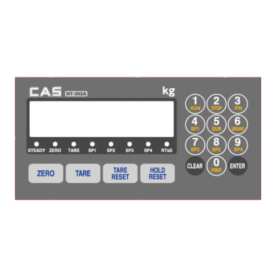
- Page 7 3-5-1. Status Lamp (ANNUNCIATORS) : Green Color Lamp is “ON”. When the weight is Steady, “▼” Lamp is turn on. Steady When the current weight is Zero, “▼” Lamp is turn on. Zero (Displayed weight is Zero, “▼” Lamp is turn on.) Tare function is set, “▼”...
-
Page 8: Installation
You can set each weighing process as a certain P/N. And you can call certain P/N with pressing this key. P/N save : Select P/N and Enter key input. P/N call : P/N + Number key + Enter Set the SP1 value or Check the current value. - Press key and enter new set value with keypad, and press enter to save. - Page 9 ※ Function Keys (Combined Key functions : key + other keys) Time set value check or Change Date set value check or Change Code value check or Change Serial No. check or change Sub-total Data Delete Grand-total Data Delete 8 / 44...
- Page 10 3-6. Rear Panel Option Slot Load Cell Connector Power Digital Input Comm. Output -Power ON/OFF Switch ①POWER -Fuse : AC 250V 10A -AC IN : AC86~265V Power In - OPTION BOARD install slot. ②OPTION 1,2 - ANALOG out, Serial I/F, etc -EXC + (+5V) PIN1 (RED) ③LOAD CELL...
- Page 11 4. INSTALLATION 4-1. External Dimension & Cutting Size (External Dimension) (unit : mm) Cutting Size 10 / 44...
- Page 12 4-2. Formula to plan the precise weighing system This “NT-302A” weighing controller’s Max. input sensitivity is 0.45㎶ / Digit. And for precise weighing system, the following formula must be satisfied. Caution : “Input sensitivity” means Min. output voltage variation of weighing part to change Cautions 1digit.
-
Page 13: Set-Up
5. SET-UP 5-1. Calibration Adjust weight balance between “Real weight” on the load cell(Weight Part) and “Displayed weight of Indicator”. When you replace LOAD CELL or Indicator, you have to do Calibration process once again 5-2. Test Weight Calibration Prepare At least 10% of Max. capacity of your weighing scale Step 1. - Page 14 CAPA XXXXXX Step 3. Max. Capacity Setting ( display) Input Max. Capacity of Scale with No. keys. Input Capacity and press ENTER KEY, and move to next step. ※ Caution (Max. capacity value / division value) can not be over 20,000.(as Indicator resolution is 1/200,00). CAL _0_ Step 4.
- Page 15 5-3. Function Setting To make more accuracy performance of NT-301A, through this Function setting. Step 1. Enter to Function setting mode. TEST Turn on the Power + 3 KEY display SET-CAL Press 3 KEY display Press CLEAR KEY to start “F-function Mode”. Step 2.
- Page 16 5-4. Function List Function Contents Remark Set-up : Clear key Set-up / Calibration Mode Selection Calibration : Enter key Decimal point setting Setting range : 0, 1, 2, 3 Back up mode selection Setting range : 0, 1 Motion Band setting Setting range : 0 ~9 Zero Tracking setting Setting range : 0~ 9...
- Page 17 Function Contents Remark Data Transference count setting (Port No.2) Setting range : 0~6 Weight Unit Selection (Printer) Setting range : 0~2 Auto print selection Setting range : 0~1 Print format selection Setting range : 0~1 Sub-Total Data delete Selection Setting range : 0~1 Paper withdraw rate Selection Setting range : 0~9 Print Line interval Selection...
- Page 18 5-5. Function List detailed information. Set-Up / Calibration Mode Selection Clear Set-Up mode Enter Calibration Mode Decimal Point Setting ● No Decimal point place under Zero (0.0) place under Zero (0.00) place under Zero (0.000) Back up mode selection ● Normal mode Back up mode Motion Band Range setting...
- Page 19 Zero /Tare key Operation mode selection ● Activate when “Steady” condition, only Always activated Zero key Operation Range selection Activated within 2% of Max. Capacity Activated within 5% of Max. Capacity ● Activated within 10% of Max. Capacity Activated within 20% of Max. Capacity Activated within 100% of Max.
- Page 20 Hold “Off” time setting Time setting of the “Hold Off” ∫ After set time, Hold function will be off automatically. Weighing Mode Setting Weighing Mode Selection ● Limit Mode (Weighing mode 1) Packer Mode (Weighing mode 2) Checker 1 Mode (Weighing mode 3) Checker 2 Mode (Weighing mode 4) Weighing Mode Selection Relay Output...
- Page 21 ◆ Weighing Mode 1. Limit Mode 1. (F21-01 setting) - Relay “ON” when weight reaches to set value Weight Near Zero TARE(IN) Output 1 Output 2 Output 3 Output 4 Output 5 FINISH Output 6 Near Zero 1. Set value setting Sp1(Bulk), Sp2(Bulk + Drib), Sp3(Bulk + Drib + Fall), Sp4(FINAL) 2.
- Page 22 ◆ Weighing Mode 2. Packer Mode (F21-02 setting) Weight Near Zero TARE(IN) Output 1 Output 2 Output 3 Output 4 FINISH Output 5 Near Zero Output 6 1. Set value setting Sp1(Bulk), Sp2(Bulk + Drib), Sp3(Bulk + Drib + Fall), Sp4(FINAL) 2.
- Page 23 ◆ Weighing Mode 3. Comparison Mode (F21-03 setting) - Checker Mode 1. Weight Near Zero TARE(IN) Output 1 Near Zero≤ t3 t4 Steady weight<SP1 Output 2 SP1≤Steady weight<SP2 t3 t4 Output 3 SP2≤Steady weight<SP3 t3 t4 Output 4 SP3≤Steady weight<SP4 t3 t4 Output 5 SP4≤Steady weight...
- Page 24 ◆ Weighing Mode 4. Packer Mode (F21-04 setting) - Checker mode 2. Weight Near Zero TARE(IN) Output 1 Near Zero≤ Steady weight<SP1 Output 2 SP1≤Steady weight<SP2 Output 3 SP2≤Steady weight<SP3 Output 4 SP3≤Steady weight<SP4 Output 5 SP4≤Steady weight Output 6 Near Zero 1.
- Page 25 “FINISH Relay” delay time(t1) setting (Under F21- 01, 02 setting) After current weight is reached to FINAL, you can set some delay time of “FINISH relay ON time. Steady point ∫ FINISH Relay Com-Out5 “00” setting : At Steady point, FINISH relay output “20”...
- Page 26 Communication setting Parity Bit selection Mode – Port No.1(Standard) ● No Parity Odd Parity Even Parity Serial Communication Speed selection – Port No.1(Standard) 115,200bps 76,800bps 57,600bps 38,400bps 28,800bps 19,200bps 14,400bps ● 9,600bps 4,800bps 2,400bps Serial I/F Mode setting (Under F33-00 setting, only) – Port No.1(Standard) ●...
- Page 27 Transferred Data Format – Port No.1(Standard) ● Format 1. Format 2. (Format 1 + time) CAS Format BCC Selection Mode ● BCC not use BCC Use Data Transference count setting – Port 1(Standard) About 40times/sec About 30times/sec About 20times/sec ●...
- Page 28 Serial I/F Mode setting (Under F43-00 setting, only) – Port 2(Option) ● Steam Mode : Continuous Data transfer Finish Mode : Single time data transfer, after Finish relay “ON” - When Finish Relay output, Data will be output. Print Mode : Single time data transfer, when print key input Serial I/F Transference method setting –...
- Page 29 Print Format selection Continuous Print ● Serial No. and Weight will be printed continuously. Single Print Date, Time, S/N, ID No. Weighing Data will be print SUB/GRAND Total Data Delete selection Manual Delete Mode ● SUN Total Delete : “Clear” key + “SUB” key GRAND Total Delete : “Clear”...
- Page 30 Auto Print Setting ● Manual Mode : Print output, when 0 KEY input. Auto Mode : Print Output, when Finish Relay output. BCD output Selection ● Positive output Negative output Average Display setting 00 setting : Average Display mode not use ∫...
- Page 31 Other Setting EMPTY Range setting You can set “EMPTY” Range. Within set range, indicator will not display current weight and just display “Zero”. X.X.X.X.X.X. “0.000” setting : When Net Zero, “Zero” status lamp and Near Zero (0.0.0.0.1.0) relay will be output. “0.190”...
- Page 32 6. InterFace 1. Serial Interface RS-232C Serial Interface is sensitive/weak for electric Noise. So, please isolate with AC power cable and use shield cable to reduce the electric noise effect. 1-1. Signal Format ①. Type : EIA-RS-232C ②. Communication Method : Half-Duplex, Full Duplex, Asynchronous ③.
- Page 33 2E(H) : “.” Decimal Point ⑤. Unit : kg, g, t 1-.4 Communication with PC(Personal Computer) or Other devices 2 : RxD TxD : 3 3 : TxD RxD : NT-302A Personal Computer 5 : SG SG : 5 (9pins Standard) 32 / 44...
- Page 34 2. Serial Interface (option :RS- 422) RS-422/485 serial interface is more stable for electric noise effect compare with other communication method, using electric current difference. But, install isolated place from Power cable or other electric cables and wires, and please use shielded cable for better performance.
- Page 35 3. Analogue Output (option : 4~20mA or 0~10V) 3-1. Analogue Output Connection No.1 1 :Out 2 :Com. No.2 3 :N.A 4 : N.A 3-2. Specification ①. Output Current : 4~20mA (Output Range : 2~22mA) ②. Accuracy : More than 1/1,000 ③.
- Page 36 ※ Only this power part is different. 2. Data Format As same as “RS-232C” Interface 3. Communication with Other Devices (Remote Display / External Display) 1: RxD 2 : RxD NT-302A Remote Display (External Display) 4. Current Loop Circuit 35 / 44...
- Page 37 5. Command Mode 1. READ Command PC Indicator Format Command Response from Indicator RTIM 000000 STX ID.NO. Time Data RTIM STX ID. NO. BCC ETX BCC ETX RDAT 00000000 STX ID. NO. Date Data RDAT STX ID. NO. BCC ETX BCC ETX RSNO 000000 STX ID.
- Page 38 2. DATA 2 CODE NET.W (8) DATE (8) TIME (6) P/N (2) S/N (6) TARE (6) GROSS.W (8) UNIT (2) Current Weight 3. Sub-Total, Grand-Total, SP1, SP2, SP3, Sp4 data don’t have decimal point 2. Write Command PC Indicator Format Command Response from Indicator WTAR ACK...
- Page 39 PC Indicator Format Command Response from Indicator WSTC ACK STX ID. NO. BCC ETX WSTC STX ID. NO. BCC ETX Sub-Total Data Clear WSTC NAK STX ID. NO. BCC ETX WGTC ACK STX ID. NO. BCC ETX WGTC STX ID. NO. BCC ETX Grand-Total Data Clear WGTC NAK...
- Page 40 6. Serial Print Format Single Continuous Print Print Format Format Sub-Total Print Format Grand Total Print Format 39 / 44...
- Page 41 7. Error and Treatment 1. TEST Mode TEST Mode No. Contents Detail information TEST 1. Analogue TEST mode TEST 2. Keypad TEST mode TEST 3. SET.CAL Mode TEST 4. Display TEST Mode TEST 5. Relay output TEST Mode TEST 6. External input(Digital Input)TEST Mode TEST 7.
- Page 42 2. Error and Treatment 2-1. Load Cell Installation Error Cause Treatment Remark 1).Input Resistance of “EX+” and “EX- 1). Load cell broken Measure “ about Load cell input/output resistance 350Ω~450Ω. isolation of Load cell. resistance error 3). Weighing part Output Weight Value is 2).
- Page 43 2-2. Calibration Process Error Cause Treatment When Max.capacity/digit Re-input the Max. Capacity, less than 20.00 Err 01 value is over 20.00 (Max. Capacity / Digit) Standard weight value is Re-input Standard weight value with Number Err 04 over than Max. Capacity keys, under Max.
- Page 44 1. The Warrantee period, we can guarantee, is one(1) year from your purchasing date 2. Warrantee Exception Clause - Warrantee period is expired. - Any kinds of Mal-function or defection caused by Modification or Repair without CAS permission. - Any kinds of Mal-function, Defection, or External damage, caused by operator - Any kinds of Mal-function, Defection, caused by using spare part from Non-Authorized Distributor or Agent.
Need help?
Do you have a question about the NT-302A and is the answer not in the manual?
Questions and answers