Table of Contents
Advertisement
Advertisement
Table of Contents

Subscribe to Our Youtube Channel
Related Manuals for CAS CI-2400BS


Summary of Contents for CAS CI-2400BS
- Page 2 CI-2400BS Weighing Indicator OWNER’S MANUAL...
-
Page 3: Table Of Contents
CONTENTS PRECAUTIONS INTRODUCTION CI-2400BS FEATURES TECHNICAL SPECIFICATION MEASURE OF APPEARANCE FRONT PANEL DESCRIPTION REAR PANEL DESCRIPTION SEALING METHOD SYSTEM MODE GENERAL FUNCTION & DESCRIPTION SET MODE TEST MODE CALIBRATION MODE SIMPLE CALIBRATION MODE ONLY ZERO CALIBRATION GRAVITY COMPENSATION & THE OTHERS SET MODE OPTIONS ERROR MESSAGE &... -
Page 4: Precautions
PRECAUTIONS Place the indicator on a flat and stable Do not use inflammable materials in surface. cleaning. Keep the main body from rain and Do not severely press because the light pressing of keys can incite the operation. keep in dry area. - Page 5 Do not subject the scale to sudden temperature changes. Keep the scale away from strong EMI noises may cause incorrect weight readings.
-
Page 6: Introduction
Also, it is programmed for the user’s convenience and contains display functions that are easily accessible. Before using CI-2400BS, it is recommended that you read this manual carefully so you may use this device to its full potential. CI-2400BS FEATURES 1. -
Page 7: Technical Specification
3. Option Option-1 RS422 /RS485 Function Option-2 Charging Circuit + NiCd Battery (DC 7.2V, 2 0 0 0 m A h ) Option-3 Relay Output Function Option-4 (Max. DC 30V, 100mA - Zero, Under, Ok, Over) Option-5 FS-7000D Serial Printer Option-6 TECHNICAL SPECIFICATION Analog Part &... -
Page 8: Measure Of Appearance
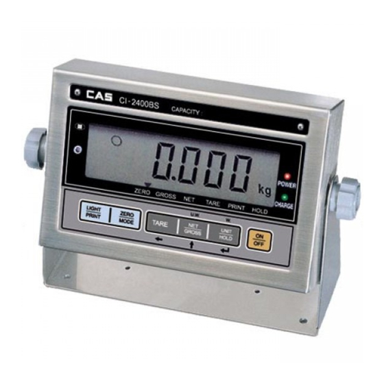
AC 110V/220V(DC 12V, 850mA) Power 1 2 W -10°C 4 0°C ( 1 4°F 104°F) consumption 2 0 0 m m 1 3 0 m m 5 3 m m Temperature Approx. 1kg(2.2lb) MEASURE OF APPEARANCE Fixed Bracket Type(CI-2400BS) - Standard CI-2400BS CAPACITY:... -
Page 9: Front Panel Description
FRONT PANEL DESCRIPTION 1. Display Part Lamp lamp: ON when the weight is stable. ZERO lamp: ON when the current weight is 0kg. GROSS lamp: ON when the weight is the total weight. NET lamp: ON when the weight is the pure weight. TARE lamp: ON when the tare weight is stored. - Page 10 2. Key Part Key functions in simple weighing mode & in weight comparing mode. Used to turn ON/OFF BACK LIGHT, F03-00. LIGHT Used to print. F03-01 PRINT Used to enter the SET MODE by pressing for 5 sec. Used to return the display to the zero. MODE ZERO (Within 2% of Max.
-
Page 11: Rear Panel Description
RS-232 Interface(TXD, RXD, GND) Connect RS-232C Port of Computer 2 Transmit Data 3 Receive Data 7 Signal Ground 4 Request To Send RS-232C port of CI-2400BS 5 Clear To Send 6 Data Set Ready 8 Carrier Detect 20 Data Terminal Ready 25pin port(Female) - Page 12 Connect Sub-display 2 Transmit Data 3 Receive Data 7 Signal Ground RS-232C port of CI-2400BS 9pin port(Male) RS-232C port of Sub-display Transmit Data Format(22 bytes) Data(8 bytes) CR LF US(Unstable) GS(Gross) Space UNIT ST(Stable) NT(Net) Device ID OL(Over load) Device ID 1 byte device ID is output to allow the receiver side to selectively receive information supplied from the indicator.
- Page 13 (kbhit( )) if ((in = getch( )) == ‘ 1B’) DONE = TRUE; bioscom(1, in, COM1); return 0; Connection FS-7000D Printer 2 Transmit Data 3 Receive Data 14 Signal Ground RS-232C port of CI-2400BS 15pin port(Female) Serial port of FS-7000D Printer...
- Page 14 Connection ND-T102, ND-192 Printer 3 Transmit Data 2 Receive Data 7 Signal Ground RS-232C port of CI-2400BS 9pin port(Female) Serial port of ND-T102(THERMAL), ND-192(DOT) Load cell Connection(EX+, EX-, SIG+, SIG-, GND) EX+: Excitation voltage+, EX-: Excitation voltage- SIG+: Sense voltage+, SIG-: Sense voltage-, GND: Shield ground Connecting method Ref 1.
-
Page 15: Sealing Method
Resolution to load cell output rate 5V impression to Load cell Max. Load cell output Recommended resolution 1/1,000(Max) 1/2,000(Max) 10mV 1/5,000(Max) Relay Output(COM, OUT1, OUT2, OUT3, OUT4) : Refer to option COM : Connect to external ground. OUT1,2,3,4 : The output circuit is an open collector type. If you hook up this line to TTL level &... -
Page 16: System Mode
SYSTEM MODE Simple weighing mode: Display the weight after weighing. High. Low weight comparing mode: Decide that the weight is high, normal or low value and perform the display. Count mode: Display the quantity by setting the unit or sample weight. Count comparing mode: Perform the display after discrimination by setting HIGH/LOW quantity. - Page 17 Ex) In case of inputting 20.5 Display Description ZERO Press one. Step 1 MODE (Set input value to ‘ 0 ’ . ) Step 2 Press twice. (Input 2 as the first place value.) Step 3 Press once. (Used to set current value 10.) Step 4...
- Page 18 3. Simple Weighing Mode Conversion Display Key Platform Description Step 1 Press once. Step 2 Press once. It is operated Empty Step 3 generally. 4. High/Low Comparing Mode Conversion In case of no resetting the High/Low value. Display Key Platform Description Step 1 Press twice.
- Page 19 In case of resetting the High/Low value. Display Key Platform Description Step 1 Press twice. Press once. ZERO (Input low weight Step 2 MODE value.) Refer to digit Step 3 input method. Step 4 Input high weight value. Step 5 Refer to digit input method.
- Page 20 5. Count Mode Conversion In case of no setting the unit/sample weight. Display Key Platform Description Step 1 Press there times. Step 2 Press once. Empty Step 3 It is operated generally. In case of setting the unit weight(Min. range of unit weight : Min. Div.) Display Key Platform Description...
- Page 21 Display Key Platform Description It is operated MODE Step 6 Empty generally. Note. If minimum division is 0.1kg in CAL mode, you can input to 0.00kg which increased a digit place than minimum division. If minimum division is 0.1kg in CAL mode, you can input to 0.00kg which increased a digit place than minimum division.
- Page 22 Display Key Platform Description Step 8 Set the unit weight. Step 9 Display unit weight. Step Press once. Empty Note 1. In case of setting the unit weight by sample count, the min. unit weight shall be more than min. division value. Note 2.
- Page 23 In case of setting the High/Low quantity. Display Key Platform Description Step 1 Press four times. Press once. MODE Step 2 Low quantity setting. Press Step 3 key. Input low quantity. MODE Step 4 Press once. High quantity setting. Press Step 5 key.
-
Page 24: General Function & Description
GENERAL FUNCTION & DESCRIPTION 1. Zero Compensation Function (Use in changing zero point.) The zero range: Within 2% of Maximum capacity. (Only available in weighing, weight-limit mode) Zero point changed. Press ZERO key. Zero compensation. 2. Tare Function (Use in weighing with tare.) Maximum TARE range: Maximum capacity Note. - Page 25 Remove the TARE and object from platform and then 3. Hold Function (Use in weighing the moving object.) Auto hold function(Hold function operates whenever it is weighed) Empty the platform. Press ‘HOLD’ key. The Hold lamp is ON. ‘AH-ON’ message displayed When the weight change The weight is averaged...
- Page 26 hold weight Empty the platform or press ‘HOLD’ key to release the hold weight and then it will be 4. Print Method 1) General Print(To print F13=1 or 2) F14=0 (Manual Print) - If you press ‘LIGHT/PRINT’ key, print current net weight.
-
Page 27: Set Mode
SET MODE 1. How to Enter If you press “LIGHT/PRINT” for 5 sec, it will be moved to SET MODE. It is display “SET” message for 1 sec, and then automatically moved to F1. 2. Available Keys key: Used to increase the first place of value by one. key: Used to move the input value to the left by one place. - Page 28 DATE, TIME C1 Year C2 Month C3 Day C4 Time C5 Minute C6 Second GENERAL FUNCTION FUNCTION Weight unit(It is set only in CAL mode) DISPLAY DESCRIPTION F1-00 F1-01 Note. Use this function depending on unit of weights which is used in CAL mode. FUNCTION Auto power OFF function DISPLAY...
- Page 29 FUNCTION LIGHT/PRINT key usage DISPLAY DESCRIPTION Only use as a BACK LIGHT key. F3-00 Not use PRINT key. BACK LIGHT always turns off. F3-01 Only use as a PRINT key. BACK LIGHT always turns on. F3-02 Only use as a PRINT key. If the weight change, BACK LIGHT will F3-03 turn on.
- Page 30 FUNCTION Digital filter DISPLAY DESCRIPTION F6-01 high speed, weak vibration F6-09 low speed, strong vibration RS232C COMMUNICATION FUNCTION RS232C baud rate set DISPLAY DESCRIPTION F10-00 2400 F10-01 4800 F10-02 9600 F10-03 19200 FUNCTION Output method RS232C data DISPLAY DESCRIPTION F11-00 No data output F11-01 Output data in state of stable &...
- Page 31 PRINTER FUNCTION FUNCTION Using printer set DISPLAY DESCRIPTION F13-00 Printer is not used F13-01 FS-7000D, 7040P serial F13-02 ND-T102(thermal), ND-192(DOT) FUNCTION Automatic print DISPLAY DESCRIPTION Manual print - whenever you press the key, F14-00 it will be printed. Automatic print - when the weight is stable F14-01 or you press the key, it will be printed.
- Page 32 AUTOMATIC HOLD FUNCTION FUNCTION Hold start delay time(Only available in automatic hold) DISPLAY DESCRIPTION F16-00 Hold operates without delay time. If the weight change, hold will operate after F16-07 14 sec. If the weight change, hold will operate after F16-15 30 sec.
- Page 33 F2000 Limit Mode WEIGHT (LOW limit) (HIGH limit) 80kg 100kg RELAY ZERO (OUT 1) (OUT 2) STABLE (OUT 3) HIGH (OUT 4) Note 1. ZERO RELAY(OUT 1) : If weight is under 5 division, this will be turned on. Note 2. LOW, HIGH RELAY(OUT 2, 3, 4) : When weight is over 5 division, comparing with setting weight value and displaying weight value, it will be turned ON/OFF.
- Page 34 DATE, TIME SET FUNCTION Set year DISPLAY DESCRIPTION C1-00 2000 year FUNCTION Set month DISPLAY DESCRIPTION C2-01 January month FUNCTION Set day DISPLAY DESCRIPTION C3-01 1st day FUNCTION Set time DISPLAY DESCRIPTION C4-00 AM 00 hour FUNCTION Set minute DISPLAY DESCRIPTION C5-59 59 minute...
-
Page 35: Test Mode
TEST MODE 1. How to Enter Turn on while pressing CAL switch on the back side. Press ZERO/MODE key, and it will be moved to Test Mode. 2. Keys Usage key: Used to move to the next menu. 3. TEST Menu TEST 1 : LCD Screen Test TEST 2 : A/D Converter Test TEST 3 : Key Test... - Page 36 TEST 2 Function: A/D Converter Test(Load Cell Test) Display Description Key : TEST 2 condition. Move to the next menu ZERO Key : Digital value of This value means converting value under Used to set the current weight. actual condition. current value to ‘0’.
- Page 37 TEST 4 Function: RS-232C Test with Computer(Serial Port) Display Description Key : TEST 4 condition. Move to the next menu Waiting for transmission and reception. Others Key : Execute data Received : none, Transmitted : 1 transmission to a Received : 2, Transmitted : 1 computer.
-
Page 38: Calibration Mode
CALIBRATION MODE 1. How to Enter Turn on while pressing CAL switch on the back side. Press TARE key and UNIT/HOLD key, and it will be moved to Calibration Mode. 2. Keys Usage key: Increase the first place value by 1. key: Move to the left by 1 place. - Page 39 CAL 2 Function: Minimum Division Set Range 0.001 50kg Display Description Key : CAL 2 condition. Control division Key : Existing minimum division Control digit Setting minimum division Key : Store and move to Press the next menu Note 1. The minimum division means the value of one division. Note 2.
- Page 40 CAL 4 Function: Zero Calibration Display Description Not being displayed CAL 4. Key : Empty the platform and when LCD screen Move to the next shows “ULOAD”, Press key. menu after completing zero calibration. Under zero calibration. Note 1. After completing zero calibration, it will be automatically moved to CAL 5. Note 2.
-
Page 41: Simple Calibration Mode
SIMPLE CALIBRATION MODE This mode is available for simply executing ZERO & SPAN calibration mode. 1. How to Enter Turn on while pressing CAL switch on the back side, and it will be moved to TEST/CAL selecting mode. Press TARE key twice, and it will be moved to simple calibration mode. And then, it will be started from zero calibration. - Page 42 Function: Span Calibration Display Description Load the maximum capacity weight and Press key. Under SPAN calibration. Key : Span calibration is terminated. Move to the initial menu ZERO=tESt It is automatically escaped from CAL mode. Press key. Tare=Cal CAL mode is completed. Move to the initial menu automatically.
-
Page 43: Only Zero Calibration
ONLY ZERO CALIBRATION 1. How to Enter Turn on while pressing CAL switch on the back side. Press TARE key and UNIT/HOLD key, it will be moved to calibration mode. Display Key Platform Description Displaying Step 1 maximum capacity. Empty Step 2 Displaying m i n i m u m... - Page 44 Display Key Platform Description Under zero Step 6 Empty calibration. Zero calibration Step 7 Empty completed. zero = tESt Empty Step 8 Tare = Cal It is escaped from zero calibration. Step 9 CAL mode is completed. Step Move to the Note 1.
-
Page 45: Gravity Compensation & The Others Set Mode
GRAVITY COMPENSATION & THE OTHERS SET MODE This mode set gravity compensation, dual range hold/unit conversion & decimal specification. 1. How to Enter Turn on while pressing CAL switch on the back side. Press LIGHT/PRINT key and it will be moved to this mode. 2. - Page 46 4. Menu Gravity Compensation Set - GRCAL : Gravity acceleration of calibrating location - GRSET : Gravity acceleration of using location Multi-interval: Dual HOLD/UNIT conversion: Hold Decimal point: Comma GRCAL FUNCTION Gravity acceleration of calibrating location DISPLAY DESCRIPTION GRCAL GRCAL condition (9700 9900) 9798...
- Page 47 Amsterdam 9.813m/s Manila 9.784m/s Athens 9.800m/s Melbourne 9.800m/s Auck land NZ 9.799m/s Mexico City 9.779m/s Bangkok 9.783m/s Milan 9.806m/s Birmingham 9.813m/s New York 9.802m/s Brussels 9.811m/s Oslo 9.819m/s Buenos Aires 9.797m/s Ottawa 9.806m/s Calcutta 9.788m/s Paris 9.809m/s Capetown 9.796m/s Rio de Janeiro 9.788m/s Chicago 9.803m/s...
- Page 48 DUAL FUNCTION Multi-interval DISPLAY DESCRIPTION DUAL DUAL condition Not use multi-interval function Use multi-interval function Press key. Note 1. In case of setting S1-0, standard division set in CAL mode is used. maximum capacity. Note 2. In case of setting S1-1, the following division is used in the following range. 0 ~ 1/2 of MAX.
-
Page 49: Options
Connecting method of RS-485/422 PORT IN(+) Transmit Data(+) IN(-) Transmit Data(-) OUT(+) Receive Data(+) OUT(-) Receive Data(-) RS485 Port of CI-2400BS Serial port of Computer IN(+) 6 Transmit Data(+) IN(-) 4 Transmit Data(-) OUT(+) 5 Receive Data(+) OUT(-) 7 Receive Data(-) - Page 50 Connect output port of adapter to CN1 of charge board after confirming polarity of adapter. Connect CN2 of charge board to CN1 of CI-2400BS main board. 4) Method If adapter code is connected to AC power to charge the battery power lamp is When charging battery, charging lamp(RED lamp) is ON.
-
Page 51: Error Message & Trouble Shooting
ERROR MESSAGE & TROUBLE-SHOOTING 1. In Weighing Mode CH 01 Reason: The calibration isn’t executed or the data of internal memory is lost by a electrical shock. Trouble shooting: Perform the required specification again in calibration mode. CH 02 Reason: The load cell is connected wrongly or A/D conversion part has a fault. Trouble shooting: Check that the load cell is well connected with main unit. - Page 52 2. In Calibration Mode CH 11 Reason: Resolution(maximum capacity/minimum division) is over the limit (1/10,000). Trouble shooting: Lower the resolution in any of the below ways. Modify maximum capacity in CAL 1 of CAL mode. Modify minimum division in CAL 2 of CAL mode. CH 12 Reason: Span setting weight is set under 10% or over 100% of the maximum capacity.
Need help?
Do you have a question about the CI-2400BS and is the answer not in the manual?
Questions and answers